Note: Descriptions are shown in the official language in which they were submitted.
CA 02535700 2011-04-14
TITLE OF THE INVENTION
Device for Stabilizing the Engine Inlet Flow in Static Tests of
Engines
FIELD AND BACKGROUND OF THE INVENTION
The invention relates to an apparatus using an air-permeable
element for the stabilization of the engine inlet flow in engine
static tests. This apparatus is used in connection with engine
static tests for the stabilization of the inlet flow of an engine
that flows in at the engine inlet or intake. With it, the effort
or expense for the preparation of an engine static test, which
will arise for the arrangement and installation or assembly of
a surfacial or planar component in front of the engine and
including its appropriate adjustment, is reduced to a justifiable
measure. Shunting or shuttling problems, which often cause a
considerable effort in connection with an intended engine static
Is test due to changing the resting location of the required
apparatus from the place it was set down to below the standing
plane of the aircraft, whereby additionally still the lifting and
adjustment effort of the surfacial or planar component is to be
considered, will be things of the past, which could cause a
considerable effort particularly in the use of known apparatuses
for the stabilization of the engine inlet flow in engine static
tests on high capacity passenger and transport aircraft.
- 1 -
CA 02535700 2011-04-14
Such an apparatus for the stabilization of the engine inlet flow
in engine static tests was already made known to the technical
world with the DE 197 43 591 C2. From the figures 2 to 4 thereof
with the correlating figure descriptions, the person of skill in
this art will recognize an apparatus for the stabilization of the
engine inlet flow in engine static tests, which similarly
comprises an (apparatus with an) air-permeable element, that is
arranged before or in front of the engine inlet and that extends
along over the engine inlet. This element, which is embodied or
constructed half-cylindrical and of one piece, is, during the
preparation phase for the intended engine static test, positioned
near the engine housing with suitable transport means and lifting
tools, which are not discussed in further detail, and is there
adjusted into a provided element setting or adjustment in a
manner that requires very much effort, such that the
air-permeable element is arranged partially enclosing or reaching
around the outer perimeter of the engine housing. The
technological effort that the construction of this apparatus will
require is evaluated as very high, whereby further it must be
considered that probably dangers can never be excluded, which can
if applicable only be limited to remaining residual dangers
during the transport and the lifting process of the (not exactly
lightweight constructed) air-permeable element to near the
applicable wing-mounted engine on the aircraft, as well as in its
orientation into a desired position below the engine housing.
The background of the use of such an arrangement exists because
in engine static tests, the influence of the (surely)
air-impermeable ground or floor or taxiway for an aircraft as
- 2 -
CA 02535700 2011-04-14
well as an excessive lateral wind effect on the arrangement for
the engine static test would lead to unacceptable or
impermissible flow conditions, whereby it results in the creation
of a spiral vortex between the ground and the engine inlet, which
form an air chamber. If now a spiral vortex forms in front of
the engine inlet on the mentioned air-permeable element, then,
as a result of the permeability of its wall surface, air can flow
after or followingly into a vortex core of the spiral vortex,
whereby the pressure in the vortex core will increase, the
angular momentum of the air particles is reduced, and the vortex
strength is diminished.
In that regard, for example, the reduction of the vortex strength
can be strengthened by the blowing-out of air through the
air-permeable surface of that element. To the extent that a
sufficient after-flow of air through this element is ensured, the
creation of a developed or distinct spiral vortex is completely
prevented.
The publication DE 197 43 591 C2 can provide additional detail
informations to an interested expert or person of skill, which
publication correspondently gives information about aerodynamic
relationships, which, as a background, relate to the undesired
flow conditions (instabilities) during the flight operation on
an engine, and to the ground effect in the engine static test as
well as, in the foreground or principally, to the presented
apparatus for the stabilization of the engine inlet flow in
engine static tests.
3 -
CA 02535700 2011-04-14
The prior art closest to this invention will mainly be directed
to the construction of the apparatus for the stabilization of the
engine inlet flow in the engine static tests and the associated
technological course or progression during the preparation of an
engine static test on the wing-mounted engine of an aircraft, to
which is allocated the presented apparatus with the indicated
disadvantages (unavoidable transport distances, more-difficult
handling, constant time delays due to re-adjustments of the
air-permeable element), which shall be improved or, if
applicable, avoided.
SUMMARY OF THE INVENTION
Therefore, the object underlies the invention, to improve a
generic apparatus for the stabilization of the engine inlet flow
in engine static tests in such a manner that the air-permeable
element (as a component of an apparatus) is positioned without
problems and without manual effort near a wing-mounted engine of
the aircraft that has been moved or set into the static test
arrangement, whereby no additional transport capacities may
arise. Endangerments are to be completely avoided through
technological improvements of the known lifting and adjusting
technology(ies) of this element, which can be realized through
an improvement of the construction of the air-permeable element.
The apparatus shall be utilizable rationally and independent of
the weather.
4 -
CA 02535700 2011-04-14
BRIEF DESCRIPTION OF THE DRAWINGS
The invention is explained in further detail in an example
embodiment in connection with the accompanying drawings. In this
regard
Fig. 1 shows the apparatus for the stabilization of the
engine inlet flow in engine static tests with an
air-permeable element set into the taxiway, and an
engine positioned above the element (longitudinal
section in the vertical engine axis);
Fig. 2 shows the air-permeable element positioned at the
height of and near the engine, which element is
integrated of several element parts folded or tilted
to the engine housing (vertical section parallel to
the inlet plane of the engine).
DETAILED DESCRIPTION OF EXAMPLE EMBODIMENTS OF THE INVENTION
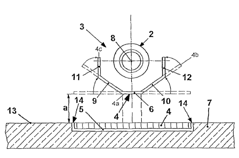
The apparatus consists of an arrangement, which mainly comprises,
besides other components, an air-permeable element 4. The
illustration of the figures 1 and 2 show an air-permeable element
4, that is integrated (clearly recognizable in the Fig. 2) of
several air-permeable element parts 6, 9 to 12 (element surfaces)
that are tiltable or foldable toward the engine housing 2. In
one (of the possible) end position(s), that air-permeable element
4 is positioned situated very close to an engine housing 2, which
5 -
CA 02535700 2011-04-14
element 4 is arranged partially enclosing or reaching around the
latter.
Returning to the Fig. 1, one can see that that air-permeable
element 4, which is integrated from a first element part 6 and
further element parts 9 to 12, is initially laid or set down on
a planar configured floor or ground 7 (in horizontal position or
orientation).
A ground area is cut out of or recessed into the ground 7. On
the ground rim or perimeter side, a ground boundary 5 is bordered
to or framed into the recess of the ground 7, which boundary is
adapted or fitted to the form of the air-permeable element 4 that
is integrated (out of several element parts 6, 9 to 12). Within
the ground boundary 5 (for example massively constructed with
angle or edge elements), the air-permeable element 4 is arranged
with a planar surface, of which the non-ground-contacting surface
region is arranged flush with a ground-opposite side region 14
(of the bounding angle or edge elements) of the ground boundary
5, or at nearly flush at least with the ground surface of the
ground 7.
Under actual or real test conditions, the observer will find out
that engine static tests will hardly ever take place on a parking
surface of the selected aircraft. For reasons of noise
protection, the static tests are displaced into engine static
test arrangements. These generally consist of three fixed or
solid walls, and are oriented so that the fixed or solid walls
- 6 -
CA 02535700 2011-04-14
screen-off the sound to the built-up districts or areas.
Thereby, the position of the aircraft in the arrangement is
prescribed, and the aircraft cannot be oriented in the wind
direction as is typical in static tests in open or free terrain.
Therefore, one can begin from the assumption that a taxiway
covering 13 (concrete runway) is laid or applied on the surface
of the ground 7. A covering area is cut out or recessed into
this taxiway covering 13, which is arranged congruent to the
(previously mentioned) recessed or cut-out ground area.
This area of the recessed or cut-out taxiway surface is fitted
or adapted to the integrated form (of several element parts 6,
9 to 12) of the air-permeable element 4, whereby the
air-permeable element 4 (which lies with the underside in contact
on a ground element within the ground boundary 5) shall terminate
or align with the non-ground-contacting upper side substantially
flush with the upper surface of the taxiway covering 13. Out of
the intended reasons, of course, since the thusly arranged
air-permeable element 4 shall cause no damage during the
rolling-over of a running surface, for example of an aircraft
wheel. It is also embodied -in such a manner that it is able to
be rolled over and capable of being rolled over by a land vehicle
or a ground-contacting air vehicle, without suffering damage.
One can substantially gather all of these facts from the Fig. 1.
Not shown in the Fig. 1, but indispensable for the desired
arrangement of the air-permeable element 4 according to the Fig.
- 7 -
CA 02535700 2011-04-14
2, is a lifting and tilting or folding unit positioned below the
ground overlay, which unit is installed sunken into the ground.
Thus, the air-permeable element 4 (horizontally situated element
parts 4, 9 to 12) horizontally arranged on the ground 7 (or set
down in the ground boundary 5) can be lifted with the lifting
mechanism of the lifting and folding unit vertically into an
intermediate position 4a located at a vertical spacing distance a
that is located below the engine housing 2 and situated close to
the latter, of which the ground-contacting horizontal position
is maintained unchanged.
Thereby, the conditions or requirements would be met for a
lifting of the air-permeable element 4 to a height level that is
located near the engine housing 2. It is intended to lift the
air-permeable element 4 with a first air-permeable embodied
planar element part 6 to an intermediate position 4a, which (in
this end position) is arranged below or under the engine housing
2 for the initially explained reasons. In this position, the
(horizontally situated) arrangement of the air-permeable element
4 (consisting of several element parts 6, 9 to 12) is positioned
along a horizontal engine housing axis 8 and parallel to a planar
ground 7 respectively (according to Fig. 2) of a taxiway surface
13 at a vertical spacing distance a. The construction of this
air-permeable element 4 takes into consideration, that on the
surfacial rim side on the longitudinal edges thereof, that are
situated along the engine housing axis 8, further air-permeable
embodied planar element parts 9 to 12, that are embodied or
constructed to be tiltable or foldable out of a (existing)
- 8 -
CA 02535700 2011-04-14
horizontal position to the engine housing 2, are further
downstream arranged laterally or sideways of the longitudinal
edges.
This construction further takes into consideration that a second
element part 9 and a third element part 10 are respectively
rotatably or pivotably supported and mechanically securely
connected on the longitudinal edge side on a first longitudinal
edge and on a second longitudinal edge respectively, to the
(previously mentioned) first element part 6. Situated next to
the second element part 9, on a third longitudinal edge of the
latter, a fourth element part 11 is arranged, whereby also
situated next to the third element part 10, on a fourth
longitudinal edge of the latter, a fifth element part 12 is
arranged. These element parts 9 to 12 are all rotatably or
pivotably supported and mechanically securely connected on the
longitudinal edge side.
With respect to the rotatability or pivotability and the secured
connection of the element parts 9 to 12, there is a broad range
or selection of suitable known connection possibilities of two
adjacently situated element parts available to the person of
skill in the art, which he will take into account as required for
the particular purpose.
A tilting or folding mechanism is also integrated into the
lifting and folding unit, with which the further element parts
9 to 12, which are embodied to be foldable and facing toward the
- 9 -
CA 02535700 2011-04-14
first element part 6, can be moved out of the mentioned
intermediate position 4a into an end setting or position. In
that regard, depending on the desired position or orientation,
the air-permeable element 4 will take-up the most varied end
6 positions. Preferably a (second) end-position is mentioned,
which will correspond to an end position of the air-permeable
element 4 located close to the engine housing 2.
In detail, at least three end positions 4a, 4b, 4c, which will
be set forth in the following, are achievable with the
air-permeable element 4 consisting of several element parts 6,
9 to 12.
A first end position is considered as given when none of the
element parts 9 to 12 is angled to the first element part 6, so
that the intermediate position 4a corresponding to the horizontal
arrangement of all element parts 6, 9 to 12 coincides with a
first end setting or position.
A second end setting is achieved when the second and the third
element part 9, 10 is angled to the first element part 6 at the
edge rim side, and the second and the fourth element part 9, 11
as well as the third and the fifth element part 10, 12 are
arranged lying next to one another and not angled from one
another as well as aligning flush in a straight line. Insofar
as these flush aligned element parts 9 to 12 are moved (pushed)
with the folding mechanism of the lifting and folding unit out
26 of the intermediate position 4a and are angled from the first
10 -
CA 02535700 2011-04-14
element part 6 at the edge rim side to a setting or position near
the engine housing 2, the second end setting 4b is reached.
Otherwise, a third end setting is reached, when the second and
the third element part 9, 10 is angled to the first element part
6 on the edge rim side, and the fourth element part 11 is
moreover still angled from the second element part 9, as well as
the fifth element part 12 is moreover still angled from the third
element part 10. Thereby, the third end setting is realized,
when the fourth and fifth element part 11, 12 is arranged
perpendicularly to the first element part 6, whereby the third
and fourth element part 10, 11 can be moved with the tilting or
folding mechanism of the lifting and folding unit out of a
position corresponding to the second end setting 4a into a third
end setting 4c.
A preference is granted to the latter end setting 4c, because
therewith the initially mentioned spiral vortex in this
constellation can be most effectively influenced, thus namely the
interfering influence thereof can be prevented.
To that, the following will still be added. A vertical lifting
of all element parts 6, 9 to 12 of the air-permeable element 4
is effectuated with the lifting mechanism of the lifting and
folding unit. Moreover, a tilting or folding of the further
element parts 9 to 12 is realized with the folding mechanism of
the lifting and folding unit, which will take place throughout
during the lifting process.
- 11 -
CA 02535700 2011-04-14
The first element part 6 can be embodied parallelepiped or cube
shaped, of which the base and cover or top surfaces are
configured square or rectangular shaped. The further element
parts 9 to 12 can be embodied variously, preferably
parallelepiped or cube shaped, or uniformly only square or cube
shaped, of which the base or cover or top surface is configured
square or rectangular shaped. The configuration of the element
parts 6, 9 to 12 will remain left to the desired selection for
the intended purpose.
It is intended, that the first element part 6 and the further
element parts 9 to 12 are embodied uniformly long along the
engine housing axis 8 of an engine 3. Moreover it could be
intended that the length of the fourth and of the fifth
perpendicularly arranged element part 11, 12 as seen relative to
one another is embodied with differing length.
Lastly, further details will be given as to the provided material
for the element parts 6, 9 to 12, whereby a material of the
element parts 6, 9 to 12 is taken into consideration, which is
pressure and weather resistant as well as being embodied
substantially light in weight. The material could consist of
metals or synthetic plastic type materials or could be composed
of both components. Thereby it would be conceivable, that a
suitable synthetic plastic (thermoplastic) would find
corresponding consideration, which is compounded or filled with
metal particles or some other substances suitable for the
purpose, which are useful to the material strength. Also it
- 12 -
CA 02535700 2011-04-14
would be conceivable, that the element parts 6, 9 to 12 are
constructed of a metal core and a synthetic plastic surrounding
the latter, of which at least the metal core is synthetic plastic
coated.
Summarized, the apparatus for the stabilization of the engine
inlet flow in engine static tests, consists of an arrangement
which mainly comprises an air-permeable element 4 formed of
several element parts 6, 9 to 12, that are embodied tiltable or
foldable to an engine housing 2. Through a suitable lifting and
folding mechanism of a lifting and folding unit, the
air-permeable element 4, as emphasized with dashed lines in the
Fig. 1, can be lifted into an intermediate position 4a which, if
applicable, could correspond to a first end setting. The lifting
and folding of the air-permeable element 4 is schematically
illustrated in the Fig. 2. The second to fifth element parts 9
to 12 realize, in common together with a horizontal first element
part 6 (remaining in the intermediate setting 4a), various
different end settings of the presented air-permeable element 4.
- 13 -