Note: Descriptions are shown in the official language in which they were submitted.
CA 02535975 2006-02-09
Effluent Interceptor With Solids Removal
BACKGROUND
[0001] It is known to pass an effluent from food processing facilities or
other
operations through devices for removing waste, such as grease, to enable the
waste to
be kept out of a sewage system. Examples of such devices are shown in U.S.
Pat.
Nos. 5,705,055, 6,423,213, and 6,776,900. Some of these devices work by
pumping
out grease or oil floating on the surface of a body of water, using an
external pump
which collects the grease or oil and deposits it elsewhere.
[0002] In order to remove solids from the effluent, some devices place a
filter
over an inlet pipe to catch the solids as the effluent passes through the
inlet pipe. In
these devices, the filter remains disposed in a constant stream or pool of
effluent
which makes the filter soggy and less desirable to be changed. Due to the
messy
nature of changing a filter that is sitting in a stream or pool of effluent,
many users
do not change the filter as often as recommended.
SUMMARY
[0003] In accordance with one aspect of the invention, an interceptor is
provided having an inlet chamber and a solids removing chamber disposed above
the
inlet chamber. A pump in the inlet chamber pumps effluent though a conduit to
the
solids removing chamber. A filter at the end of the conduit catches any solids
as the
effluent passes therethrough. A drain is provided in the solids removing
chamber to
allow the filtered effluent to return to the inlet chamber. As a result, the
filter is kept
in a dry place thus allowing a user to change a dry, less disgusting filter.
CA 02535975 2006-02-09
[0004] Numerous other advantages and features of the present invention will
become readily apparent from the following detailed description of the
invention and
the embodiments thereof, from the claims and from the accompanying drawings.
BRIEF DESCRIPTION OF THE DRAWINGS
[0005] The invention as well as embodiments and advantages thereof are
described below in greater detail, by way of example, with reference to the
drawings
in which:
[0006] Figure 1 is a cross-sectional view of an interceptor;
[0007] Figure 2 is a cross-sectional view of the solids removing chamber of
the interceptor of Figure 1 in an unfilled state;
[0008] Figure 3 is a cross-sectional view of the solids removing chamber of
the interceptor of Figure 1 in a filled state;
[0009] Figure 4 is a cross-sectional side view of the dam of the interceptor
of
Figure l;
[0010] Figure 5 is a front cross-sectional view of the dam of the interceptor
of Figure l; and
[0011] Figure 6 is a perspective view of the dam of the interceptor of Figure
1.
DETAILED DESCRIPTION
[0012] While this invention is susceptible of embodiment in many different
forms, there are shown in the drawings and will be described herein in detail
specific
embodiments thereof with the understanding that the present disclosure is to
be
2
CA 02535975 2006-02-09
considered as an exemplification of the principles of the invention and is not
intended to limit the invention to the specific embodiments illustrated.
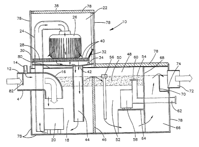
[0013] Fig. 1 illustrates an interceptor 10 that is a first embodiment of the
present invention. The interceptor 10 includes a plurality of exterior walls
78, an
inlet pipe 12 and an outlet 72. The size, shape and material used to construct
the
interceptor 10 may vary from the illustrated embodiment. The inlet pipe 12
includes
a vent 14 to introduce air into the effluent as it enters the interceptor 10.
Additionally, the inlet pipe 12 includes a flow restrictor 82 to limit the
flow rate of
the effluent entering the interceptor 10. The reduced flow rate prevent excess
turbulence in the effluent and as a result, helps the separation process.
[0014] In the interior of the interceptor 10 there is located a first baffle
46
which, along with the exterior walls 78 and the upper wall 80, defines an
inlet
chamber 18. A first pump 20 is positioned in one lower corner of the inlet
chamber
18. The first pump 20 as illustrated is a sump pump but may be another type of
pump. The first pump 20 has an outlet which connects to a conduit 24 that
terminates in a solids removing chamber 22.
[0015] The interceptor 10 also includes a drain duct 44 located in the inlet
chamber 18 at a diagonally opposite corner from the first pump 20. The
location of
the drain duct 44 within the inlet chamber 18 may vary.
[0016] As shown in Fig. l, the top of the first baffle 46 is below a static
level
54. The static level 54 is the highest level that the effluent will reach at
equilibrium
when the interceptor is at maximum capacity. The first baffle 46 may extend
above
the static level 54 and have openings below the static level 54 in order to
allow
effluent to flow therethrough.
[0017] Above the inlet chamber 18 is the solids removing chamber 22. In the
illustrated embodiment, the solids removing chamber 22 is directly above the
inlet
chamber 18. The solids removing chamber 22 does not have to be directly above
the
3
CA 02535975 2006-02-09
inlet chamber 18. For example, the solids removing chamber 18 may be offset
horizontally from the inlet chamber 18, so long as the force of gravity can
return
filtered effluent to the inlet chamber 18. A pump may also be used to help
return the
filtered effluent to the inlet chamber 18 if the solids removing chamber 22 is
not
directly above the inlet chamber 18.
[0018] The solids removing chamber 22 includes a lid 38 which opens to
allow access to the chamber 22. As shown in Fig. 1, the lid 38 may be hinged
at one
end. The attachment of the lid 38 is not critical so long as it provides
access to the
chamber 22 from the exterior. The interceptor 10 also includes a filter 26
disposed at
the end of the conduit 24 in the solids removing chamber 22. The filter 26 may
be a
disposable, easily changed, porous pliable bag which catches solids in the
effluent
but still allows the effluent (absent solids) to pass therethrough.
[0019] The filter 26 sits above, and, when filled, on, a platform 28. The
platform 28 is hinged at one end and attached to a spring 32 at the other end.
The
hinge is attached to a sidewall 30 of the solids removing chamber 22 and the
spring
32 is attached to the interior side of the exterior wall 78. This arrangement
allows
the platform 28 to pivot downwardly as the weight from the filter 26 pushes
against
the platform.
[0020] Below the platform 28 is a switch 34. When the weight of the filter
26 is great enough, the platform 28 pivots down far enough to contact the
switch 34
which in turn activates an alarm 36 as described below. This mechanical
arrangement may be replaced by other arrangements which sense the fullness of
the
filter 26 and provide an indication of when the filter 26 needs to be
replaced.
[0021] The platform 28 includes a plurality of holes 40 which allow filtered
effluent to pass through the platform 28. The passing of the filtered effluent
may
also be accomplished in many other ways. For example, the platform 28 may be
sized smaller than the footprint of the solids removing chamber 22 which would
then
permit filtered effluent to run over the edges of the platform 28. Below the
platform
4
CA 02535975 2006-02-09
28 is a drain 42. The drain 42 provides a passage for the filtered effluent to
return to
the inlet chamber 18. In the illustrated embodiment, the drain 42 includes and
is
attached to the drain duct 44. In this manner, filtered effluent can be
directed to a
specific location within the inlet chamber 18.
[0022] The first baffle 46 separates the inlet chamber 28 from an effluent
separation chamber 48. The effluent separation chamber 48 is defined by the
first
baffle 46, a second baffle 68, and the exterior walls 78. Located in the
effluent
separation chamber 48 is a second pump 58. In the illustrated embodiment, the
second pump 58 is an inverted submersible pump with its inlet 60 directed
upward.
By being submersible, the second pump 58 can be disposed within the
interceptor 10
and within the effluent. In other embodiments, the second pump 58 does not
have to
be submersible nor does it have to be inverted. The second pump 58 sits atop a
support 64 to dispose the inlet 60 in the correct location. In the illustrated
embodiment, the inlet 60 is disposed approximately 2 inches below the static
level
54. However, the distance between the inlet 60 and the static level 54 may be
different, so long as the inlet 60 is disposed within a grease layer 50 when
the
interceptor 10 is full.
[0023] The second pump 58 also includes an outlet pipe 62. The outlet pipe
62 is a conduit to direct removed grease to its desired location, such as, for
example,
a grease container. The grease container or other desired location for the
removed
grease may be exterior to the interceptor 10.
[0024] Also disposed in the effluent separation chamber 48 is a waste level
probe 56. The waste level probe 56 measures the thickness of the waste layer
(i.e.
grease layer 50). The waste level probe 56 may be any type such as, but not
limited
to, the ones described in U.S. Patent Nos. 5,705,055, 6,423,213 and 6,776,900.
The
waste level probe 56 may also be capable of turning the second pump on and off
depending of the level and thickness of the grease layer 50. This can be
accomplished by logic within the waste level probe 56 or by logic separate
from the
waste level probe 56.
CA 02535975 2006-02-09
[0025] The second baffle 68 includes an opening at its bottom to allow clean
water to flow therethrough and into a clean water chamber 66. The clean water
chamber 66 includes an outlet 72 through which the clean water exits the
interceptor
10. The outlet 72 is disposed on the upper portion of the exterior wall 78.
The outlet
72 may, alternatively, be disposed on any other wall of the clean water
chamber 66.
[0026] A dam 70 disposed around the outlet 72 sets the static level 54 and
raises it above a lowest edge 74 of the outlet 72. Without the dam 70, the
static level
54 would be set by the lowest edge 74 of the outlet 72 because water entering
clean
water chamber 66 would begin to exit through the outlet 72 as soon as the
water
level reached the lowest edge 74. Because of the dam 70, the water level must
reach
and flow over the upper edge 76 of the dam 70 before it is able to exit the
interceptor
through the outlet 72. The static level 54, as a result, is set by upper edge
76 of
the dam 70 which is above the lowest edge 74 of the outlet 72. Consequently,
the
interceptor 10 can hold a greater volume of effluent.
[0027] The dam 70, as illustrated, includes four walls and is attached to the
exterior wall 78 of the interceptor 10. The dam 70 may be shaped in many
different
ways and does not have to be disposed on the exterior wall 78 of the
interceptor 10.
For example, the dam 70 may be a baffle, similar to the first baffle 46, but
having an
upper surface that is higher than the lowest edge 74 of the outlet 70.
[0028] The interceptor 10 is used to remove waste material from an effluent.
An effluent is defined as any fluid containing at least one type of waste
material
therein. The waste material may be in the form of a liquid or solid. For the
purposes
of explanation, the effluent used to explain the operation of the illustrated
interceptor
10 is considered to contain initially a mixture of water, grease and solid
waste (such
as pieces of food). The interceptor 10 removes the grease and solid waste from
the
effluent to allow clean water to exit therefrom.
[0029] Effluent enters the inlet pipe 12 where it is mixed with air from the
vent 14. The air that is mixed in with the effluent attaches to the grease,
helping to
6
CA 02535975 2006-02-09
separate the grease from the water. The effluent flows through the inlet pipe
12 and
is directed downward by an elbow 16 of the inlet pipe 12. After being directed
downward by the elbow 16, the effluent flows into the inlet chamber 18 of the
interceptor 10.
[0030] At this point, the effluent contains, for purposes of explanation,
grease, water and solid material. The first pump 20 pumps the effluent located
in the
lower portion of the inlet chamber 18 through the conduit 24 to the solids
removing
chamber 22. The solids removing chamber 22 is located above the inlet chamber
18.
[0031] The effluent is pumped through the conduit 24 (Figs. 2 and 3) and
through the filter 26. The filter 26, in the illustrated embodiment, is a
pliable
disposable bag which allows the effluent to pass therethrough while catching
the
solid materials in the effluent. The solids materials remain in the filter 26.
As more
effluent passes through the filter 26, more solids materials remain in the
filter 26. As
the volume of solids materials increases, the weight of the filter 26
increases. The
weight of the filter 26 pushes against the platform 28 that is disposed
beneath the
filter 26.
[0032] In the illustrated embodiment, the platform 28 is hingedly attached at
one end to the side wall 30 of the solids removing chamber 22. The platform 28
is
also attached at the other end to at least one spring 32. As the weight of the
filter 26
increases, the filter 26 pushes against the platform 28 which causes the
platform 28
to pivot about its hinged end. When the filter 26 is full as shown in Fig. 3,
the
weight of the filter 26 will cause the platform 28 to move far enough to
contact the
switch 34. The switch 34 causes an alarm 36 to be activated to indicate to a
user that
the filter 26 is full and needs to be changed or emptied.
[0033] To change or empty the filter 26, the lid 38 of the solids removing
chamber 22 is opened to access the solids removing chamber 22. Specifically,
the
lid 38 is hinged to the side wall 30 at one end, thus allowing a user to swing
the lid
38 open and replace the filter 26. Since the filter 26 is drained and sits in
the solids
7
CA 02535975 2006-02-09
removing chamber 22 which does not have standing effluent, the filter 26 is
able to
dry out and is friendlier to change as opposed to filters of previous designs
which sit
in a pool of effluent.
[0034] Effluent that passes through the filter 26 flows through the holes 40
in
the platform 28 and into the drain 42 in the floor of the solids removing
chamber 22.
The drain 42 includes the drain duct 44 which runs from the floor of the
solids
removing chamber 22 to the lower portion of the inlet chamber 18. The effluent
flows through the drain duct 44 and into the lower portion of the inlet
chamber 18.
The drain duct 44, in the illustrated embodiment, is in a corner diagonal from
the
corner that the first pump 20 is disposed. In that way, the flow of the
effluent from
the drain duct 44 will flush solids materials sitting near the bottom of the
inlet
chamber 18 towards the first pump 20.
[0035] The effluent fills the inlet chamber 18 until the level of effluent is
higher than the first baffle 46. When the level of effluent in the inlet
chamber 18
exceeds the height of the first baffle 46, the effluent flows over the first
baffle 46 and
into the effluent separation chamber 48.
[0036] In the effluent separation chamber 48, the grease, which is less dense,
separates and floats on top of the water, which is more dense. This results in
the
fluid in the effluent separation chamber 48 having a layer of grease 50 (waste
layer)
floating on a body of water 52. The grease layer 50 floating on the body of
water 52
has a thickness measured downward from the upper surface of the grease layer
50 to
the boundary between the grease layer 50 and the body of water 52. In the
embodiment illustrated in Fig. l, the upper surface of the grease layer 50 is
shown at
the static level 54.
[0037] The thickness of the grease layer 50 is measured by the waste level
probe 56. When the thickness of the grease layer 50 is approximately three
inches,
as determined by the probe 56, the second pump 58 is turned on. The second
pump
58 has an inlet that is approximately two inches below the static level 54.
The
8
CA 02535975 2006-02-09
second pump 58 when turned on thus pumps out approximately two inches of
grease
from the grease layer 50. This can be accomplished for example by allowing the
second pump 58 to operate for a predetermined amount of time which has been
previously calibrated to remove approximately two inches of grease. The
removed
grease is pumped out of the effluent separation chamber 48 through the outlet
pipe
62. The removed grease may be pumped to a grease container (not shown)
exterior
to the interceptor 10 which can be subsequently disposed of in the proper
manner.
[0038] The body of clean water 52 continues to flow beneath the second
baffle 68 into the clean water chamber 66. The clean water fills the clean
water
chamber 66 until it overflows the top surface of the dam 70. The clean water
is
prevented by the dam 70 of entering directly the outlet 72 of the interceptor
10. As
stated above, the dam 70 prevents the clean water from flowing directly into
the
outlet 72 of the interceptor 10. This raises the static level 54.
[0039] By raising the static level 54, the amount of space used in the
interceptor 10 is maximized. In other words, an interceptor 10 having a dam 70
which raises the static level 54 can hold a greater volume of effluent than an
identical-sized interceptor that does not have such a dam 70. By adding a dam
70, an
interceptor manufacturer can increase the capacity without increasing the size
of the
interceptor. This is important as interceptors are usually stored in
relatively small
spaces. In addition, the increased capacity provides a longer residence time
for
effluent in the interceptor 10, which can increase the separation efficiency.
[0040] The above description of some of the embodiments of the present
invention has been given by way of example. From the disclosure given, those
skilled in the art will not only understand the present invention and its
attendant
advantages, but will also find apparent various changes and modifications to
the
structures and methods disclosed. It is sought, therefore, to cover all such
changes
and modifications as fall within the spirit and scope of the invention, as
defined by
the appended claims, and equivalents thereof.
9