Note: Descriptions are shown in the official language in which they were submitted.
CA 02536160 2006-02-17
WO 2005/018427 PCT/US2004/026877
SPRING-LOADED AWL
FIELD OF THE INVENTION
[0001] The present invention relates generally to an awl for use in orthopedic
surgery,
and more particularly to an awl having a cutting tip that is used to create or
enlarge holes in
bone.
BACKGROUND OF THE INVENTION
[0002] The present invention relates generally to an awl for use in orthopedic
surgery.
Awls generally in orthopedic surgery are used to create or enlarge holes in
bone. Although a
drill may be used to create a hole in bone for orthopedic surgery, the
precision required in
aligning holes, for example, for vertebral surgery, requires the use of a
drill guide along with
the drill. Rather than using two devices, the present invention allows a
surgeon to use a
single device to create a properly aligned hole. An awl may also be used for
creating starter
holes for self drilling screws, although it is not limited to such uses.
SUMMARY OF THE INVENTION
[0003] The present invention relates to an awl used in orthopedic surgery. The
awl of
the present invention in one embodiment has a shaft with a cutting tip, a
spring, a bottom
outer sleeve, a top outer sleeve, an inner sleeve, and a hand grip. More
particularly the
cutting tip of the awl of this embodiment is normally maintained within an
outer sleeve by a
spring which provides a biasing force. In one embodiment, the awl may have a
distal end
which engages a bone plate, and a proximal end, which may have a hand grip for
operating
the awl. Preferably, the awl engages the bone plate with the awl being
oriented to match the
desired trajectory of the bone fasteners, such as for example screws, through
the bone plate.
The awl preferably engages the bone plate in a releasable manner. Applying
pressure to the
hand grip in a direction toward the distal end of the awl pushes the shaft of
the awl against
the spring which causes the cutting tip of the awl to leave the outer sleeve
and contact the
bone surface. Depending upon the pressure applied and the distance traveled by
the shaft, the
cutting tip preferably pierces the bone, with travel of the cutting tip
preferably limited by a
shoulder within the outer sleeve. Releasing pressure on the hand grip allows
the biasing force
of the spring to return the cutting tip of the awl to a position within the
outer sleeve. The
distal end of the spring rests on a shoulder inside the inner sleeve and the
proximal end of the
spring rests on a shoulder formed by the junction of the inner sleeve and the
awl shaft. The
CA 02536160 2006-02-17
WO 2005/018427 PCT/US2004/026877
outer sleeve may include slots that allow the tool to be cleaned and
sterilized between
surgeries.
[0004] The awl of the present invention in another embodiment comprises a
shaft
with a cutting edge formed on one end, an outer sleeve, and a biasing member
configured to
bias the shaft to an initial position within the outer sleeve. The shaft is
surrounded by the
outer sleeve and movable in the axial direction with respect to the outer
sleeve by a
predetermined distance to limit the depth of penetration of the cutting tip
into a bone. The
elastic member may be a coil spring, which may surround the shaft. Preferably,
one end of
the outer sleeve has a means, preferably a threaded connection, of releasably
attaching to a
bone plate. The threads at the end of the outer sleeve may be conical.
Preferably, the initial
position of the shaft is such that the cutting edge of the shaft is surrounded
by the outer
sleeve. There may be one or more slots, or openings of another shape, through
the outer
sleeve. The awl apparatus may further comprise a handle attached to the end of
the shaft.
[0005] A method of installing a bone plate to a bone surface is also
described, the
method comprising the steps of (a) contacting the bone plate to the bone
surface; (b)
contacting an awl apparatus to a first fastener hole in a bone plate, the awl
apparatus
comprising a shaft having a cutting edge formed on a distal end, an outer
sleeve within which
the shaft is axially movable, and a biasing member configured to bias the
shaft to an initial
position within the outer sleeve; (c) creating a hole in the bone by applying
axial pressure to
the distal end of the shaft; (d) removing the awl apparatus from the bone
plate while holding
the bone plate in contact with the bone surface; and (e) installing a bone
anchor through the
first fastener hole into the hole created in step (c). The awl may then be
attached to a second
fastener hole in the bone plate and steps (b) through (e) repeated for the
second fastener hole.
The awl may be attached to the bone plate prior to contacting the bone plate
to the bone
surface. Preferably, the awl is attached to the bone plate by threading.
BRIEF DESCRIPTION OF THE DRAWINGS
[0006] While preferred features of the present invention are disclosed in the
accompanying drawings, the invention is not limited to such preferred features
wherein:
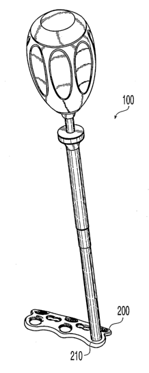
[0007] FIG. 1 is a perspective view of the awl attached to a bone plate;
[0008] FIG. 2 is a cross-sectional view of the awl of FIG. 1;
[0009] FIG. 3 is a side view of the awl shaft;
[0010] FIG. 4 is a side view of the top outer sleeve;
[0011] FIG. 5 is a side view of the bottom outer sleeve; and
-2-
CA 02536160 2006-02-17
WO 2005/018427 PCT/US2004/026877
[0012] FIG. 6 is a side view of the top outer sleeve.
DETAILED DESCRIPTION OF THE PREFERRED EMBODIMENTS
[0013] Referring to FIG. 1, there is shown an exemplary spring-loaded awl
assembly
100, engaging an anchor hole 210 of a cervical bone plate 200. Awl assembly
100 is used for
orthopedic applications that include creating or enlarging holes in bone.
While the spring-
loaded awl assembly 100 is shown and described as used with a cervical plate
200 for use in
the cervical region of the spine, it will be appreciated that the spring-
loaded awl assembly
100 can be used with other bone plates. As shown in FIG. 2, assembly 100
includes a top
outer sleeve 110, a bottom outer sleeve 120, an inner sleeve 130, an awl shaft
140, a spring
150, and a hand grip 160. All components may be fabricated from a
biocompatible material
such as stainless steel. Hand grip 160 may be fabricated from plastic or
rubber, preferably
silicone rubber to allow assembly 100 to be subjected to high temperatures for
sterilization,
for comfort, to reduce weight, and for ease of fabrication. Applying pressure
to hand grip
160 against the biasing force of spring 150 causes the cutting tip 142 of awl
shaft 140 to exit
the distal end 122 of the bottom outer sleeve 120, allowing cutting tip 142
during its intended
use to contact and preferably pierce bone when, for example, the assembly is
engaged with a
bone plate in contact with bone.
[0014] With reference to FIG. 3, awl shaft 140 is approximately 200 mm long
and has
a cutting tip 142, a distal portion 144, a medial portion 146, and a proximal
portion 148,
exemplary diameters of which are about 2.5 mm, about 3.0 mm, about 3.5 mm, and
about 2.8
mm, respectively. Other dimensions for the diameter of the cutting tip, distal
portion, medial
portion, and proximal portion may also be used, and the length of shaft 140
may also be
varied. The junction of medial section 146 and proximal section 148 of awl
shaft 140 may
form a shoulder 147.
[0015] With reference to FIG. 4, top outer sleeve 110 has a flared section 112
at its
proximal end, and has a throughbore 114 with an exemplary diameter of about
2.85 mm and a
counterbored section 116 with an exemplary diameter of about 4.78 mm. Other
dimensions
for the diameters of through bore 114 and counterbore for counterbored section
116 may be
used. Distal end 115 of counterbored section 116 forms a shoulder 115a. Top
outer sleeve
has a length of approximately 80 mm, and shoulder 115a is about 25 mm from
distal end 113
of top outer sleeve 110. Shoulder 115a may be formed at different lengths.
Diametrically
opposed slots 118 through the wall 119 of top outer sleeve 110 are
approximately 2 mm wide
and approximately 30 mm long, and facilitate cleaning and sterilizing awl
assembly 100
-3-
CA 02536160 2006-02-17
WO 2005/018427 PCT/US2004/026877
between surgeries. Other dimensions and shapes of openings may be used instead
of the slots
118 described. One or more slots 118 may be provided and the slots 118 can
have the same
or different dimensions. The distal end 113 of top outer sleeve 110 has an
exemplary outer
diameter of about 6 mm to allow it to be inserted into proximal section 126 of
bottom outer
sleeve 120. Distal end 113 of top outer sleeve 110 may be externally threaded
to facilitate
releasably joining distal end 113 of top outer sleeve 110 to bottom outer
sleeve 120.
Providing a releasable connection between top outer sleeve 110 and bottom
outer sleeve 120
may allow the top and bottom outer sleeves 110, 120 to be disconnected to
facilitate cleaning
and sterilizing. Alternatively, top and bottom outer sleeves 110, 120 may be
joined by, for
example, rolling, welding, brazing, etc. Distal end 113 of top outer sleeve
110 may include a
groove 117 to facilitate joining top and bottom outer sleeves 110, 120.
[0016] With reference to FIG. 5, bottom outer sleeve 120 has a throughbore 122
with
an exemplary diameter of about 3.1 mm. The inside diameter of the bore
increases to
approximately 4.55 mm in intermediate section 124 and to approximately 6 mm in
proximal
section 126. Bottom outer sleeve 120 has a length of approximately 80 mm and
proximal
section 126 is approximately 12 mm long. The outside diameter of proximal
section 126 is
approximately 7 mm, with the remainder of bottom outer sleeve 120 having an
outside
diameter of approximately 5.85 mm. Diametrically opposed slots 128 through
wall 129 of
bottom outer sleeve are approximately 2 mm wide and about 30 mm long, and
facilitate
cleaning and sterilizing awl assembly 100 between surgeries. Other dimensions,
shapes,
locations, and number of slots 128 may be provided. Distal end 121 of bottom
outer sleeve
120 may be threaded for mechanical attachment to the perimeter of anchor hole
210 of bone
plate 200, although other methods of releasably attaching awl assembly 100 to
bone plate 200
are possible. In some cases, assembly 100 will be used with bone plates with
conical fastener
holes and distal end 121 of bottom outer sleeve 120 will then have an external
conical thread
to match the fastener holes.
[0017] With reference to FIG. 6, inner sleeve 130 has a throughbore 132 with
an
exemplary diameter of about 2.85 mm, a distal portion 134 with an exemplary
outside
diameter of 6.5 mm and a distal face 131, a flared medial section 136 with an
exemplary
maximum outside diameter of about 15.5 mm, and a proximal portion 138
approximately 15
mm long and 12 mm in diameter, with proximal face 139.
[0018] Referring again to FIG. 2, assembly of awl assembly 100 will now be
explained. Proximal portion 148 of awl shaft 140 is inserted into distal end
121 of bottom
outer sleeve 120 until shoulder 147 of awl shaft 140 rests against distal end
113 of top outer
-4-
CA 02536160 2006-02-17
WO 2005/018427 PCT/US2004/026877
sleeve 110. Spring 150 is placed over proximal portion 148 of awl shaft 140
and proximal
end 148 of awl shaft 140 is inserted into throughbore 132 of inner sleeve 130,
with inner
sleeve located on awl shaft 140 in such a position that the gap 104 between
shoulder 115a of
top outer sleeve 110 and distal face 131 of inner sleeve 130 (dimension Ll;
exemplary
dimension of about 17 mm) is slightly less than the free length of spring 150.
The travel of
the cutting tip 142 of awl shaft (and consequently the depth of hole bored) is
changed by
varying dimension Ll and the length of spring 150. It will be appreciated that
the spring
could be in a location other than around the proximal portion 148 of awl shaft
140. In
addition, an elastic member other than a coil spring could serve the same
function as spring
150. Inner sleeve 130 is mechanically joined to proximal end 148 of awl shaft
140,
preferably by welding or brazing the interface of proximal face 139 of inner
sleeve 130 and
proximal portion 148 of awl shaft 140. Bottom outer sleeve 110 is slipped over
awl shaft 140
and distal end 113 of top outer shaft 110, and top and bottom outer sleeves
110, 120 are
mechanically joined, preferably by laser welding. However, other means of
mechanically
joining top and bottom outer sleeves 110, 120, including threaded connections,
brazing, or
rolling, are possible. In addition, the outer sleeve can be a single piece.
Awl shaft 140 is
preferably free to rotate within outer sleeves 110, 120 to facilitate clearing
bone debris from
the path of cutting tip 142 as the depth of the hole being created increases.
Handle grip 160
preferably is attached to proximal portion 138 of inner sleeve 130, preferably
by molding the
handle onto proximal portion 138 of inner sleeve 130, or by bonding or gluing.
[0019] Use of the awl assembly 100 to create a hole in bone will now be
described.
Referring to FIGS. 1 and 2, awl assembly 100 is releasably attached,
preferably by a threaded
connection, to anchor hole 210 of bone plate 200. Other methods of releasably
attaching awl
assembly to anchor hole 210 of bone plate 200 are possible, such as an
expanding ferrule or
ball detents. Assembly 100 may be used as a plate holder when applying plate
200 to the
bone surface. Applying pressure in the axial direction to hand grip 160 toward
the bone plate
results in the subassembly of handle grip 160, inner sleeve 130, and awl shaft
140 traveling in
the distal direction; and cutting tip 142 of awl shaft 140 making contact with
bone. Travel of
the subassembly of handle grip 160, inner sleeve 130, and awl shaft 140 in the
distal direction
is limited by shoulder 135 of inner sleeve 130 contacting proximal face 111 of
top outer
sleeve 110. This travel limit in turn limits the depth of hole formed by awl
assembly 100.
Releasing pressure on handle grip 160 results in the subassembly of handle
grip 160, inner
sleeve 130, and awl shaft 140 returning to its original position in which
shoulder 147 of awl
shaft 140 rests against distal end 113 of top outer sleeve 110, the contact
between shoulder
-5-
CA 02536160 2006-02-17
WO 2005/018427 PCT/US2004/026877
147 and distal end 113 limiting travel of the subassembly of handle grip 160,
inner sleeve
130, and awl shaft 140 in the proximal direction. Hand grip 160 may be rotated
as axial
pressure is applied to facilitate the clearing of debris from the path of
cutting tip 142.
[0020] After the initial hole is created in the bone by awl assembly 100,
plate 200 is
held in place either by another plate holder (e.g., a rod in another threaded
hole of plate 200),
or by a surgeon's or nurse's finger. A bone screw is then inserted through
anchor hole 210
and the awl is attached to another anchor hole to drill another hole.
[0021] While various descriptions of the present invention are described
above, it
should be understood that the various features can be used alone or in any
combination
thereof. Therefore, this invention is not to be limited to only the
specifically preferred
embodiments depicted herein.
[0022] Further, it should be understood that variations and modifications
within the
spirit and scope of the invention may occur to those skilled in the art to
which the invention
pertains. Accordingly, all expedient modifications readily attainable by one
versed in the art
from the disclosure set forth herein that are within the scope and spirit of
the present
invention are to be included as further embodiments of the present invention.
The scope of
the present invention is accordingly defined as set forth in the appended
claims.
-6-