Note: Descriptions are shown in the official language in which they were submitted.
CA 02536715 2006-02-15
GASIFICATION METHOD AND DEVICE FOR PRODUCING SYNTHESIS
GASES BY PARTIAL OXIDATION OF FUELS CONTAINING ASH AT
ELEVATED PRESSURE AND WITH QUENCH-COOLING
OF THE CRUDE GAS
This invention relates to a gasification method and device for the
gasification of
solid fuels such as bituminous or lignite coals and petroleum coke for
producing
synthesis gases by partial oxidation of fuels containing ash at elevated
pressure. The
proposed method consists of metered infeed of fuel, into a gasification
reactor,
quenching in a quencher, and cleaning in a gas scrubber, to produce gases
containing
CO and HZ by partial oxidation of dust-like fuels containing ash with a
gasification
medium containing free oxygen, at high temperatures and elevated pressure.
To achieve long operating times, the pressurized jacket of the gasification
reactor
has to be reliably protected against the action of crude gas and against the
high
gasification temperatures of 1200 - 1900 °C. This is done by confining
the reaction or
gasification chamber with a cooled tubular shield that is hung in the
pressurized jacket.
The annular gap between tubular shield and pressurized jacket is flushed.
The fuel is fed to the head of the reactor in pulverized form through burners,
using a pneumatic system by the flow transport principle. The crude gas leaves
the
gasification chamber together with the liquefied slag at the bottom of the
reactor, is
cooled to a saturated state by injecting water, and is then freed of entrained
fines. The
scrubbed crude gas is then fed to further treatment steps.
The autothermic flue stream gasification of solid, liquid, and gaseous fuels
has
been known in the field of gas production for years. The ratio of fuel to
gasification
medium containing oxygen is chosen so that higher carbon compounds are
completely
cracked for reasons of synthesis gas quality into synthesis gas components
such as CO
and H2, and the inorganic components are discharged as molten slag; see J.
Carl, P.
Fritz, NOELL-KONVERSIONSVERFAHREN, EF-Verlag fair Energie- and
Umwelttechnik GmbH, 1996, p. 33 and p. 73.
According to various systems used in industry, gasification gas and molten
slag
can be discharged separately or together from the reaction chamber of the
gasification
device, as shown in DE 197 131 A1. Either systems with refractory linings or
cooled
CA 02536715 2006-02-15
systems are used for the internal confinement of the reaction chamber
structure of the
gasification system; see DE 4446 803 A1.
EP 0677 567 B1 and WO 96/17904 show a method in which the gasification
chamber is confined by a refractory lining. This has the drawback that the
refractory
masonry is loosened by the liquid slag formed during gasification, which leads
to rapid
wear and high repair costs. This wear process increases with increasing ash
content.
Thus, such gasification systems have a limited service life before replacing
the lining.
Also, the gasification temperature and the ash content of the fuel are
limited. Feeding in
the fuel as a coal-water slurry causes considerable losses of efficiency - see
C. Higman
and M. van der Burgt, "Gasification", Verlag ELSEVIER, USA, 2003. A quenching
or
cooling system is also described in which the hot gasification gas and the
liquid slag are
carried off together through a conduit that begins at the bottom of the
reaction chamber,
and are fed into a water bath. This joint discharge of gasification gas and
slag can lead to
plugging of the conduit and thus to limited availability.
DE 3534015 A1 shows a method in which the gasification media, powdered coal
and oxidizing medium containing oxygen, are introduced into the reaction
chamber
through multiple burners in such a way that the flames are mutually deflected.
The
gasification gas loaded with powdered dust flows upward and the slag flows
downward
into a slag-cooling system. As a rule, a device is provided above the
gasification
chamber for indirect cooling and utilization of the waste heat. However, there
is the
danger of plugging of the pipe system with, and/or erosion by the entrained
dust. By
separating the gasification gas and the slag, there is the danger of unwanted
cooling of
the slag and thus likewise the danger of plugging.
CN 200 4200 200 7.1 describes a "Solid Pulverized Fuel Gasifier", in which the
powdered coal is fed in pneumatically and gasification gas and liquefied slag
are
introduced into a water bath through a central pipe for further cooling. This
central
discharge in the central pipe mentioned is susceptible to plugging which
interferes with
the overall operation, and reduces the availability of the entire system.
It is now an object of this invention, proceeding from this state of the art,
to
provide a gasification method and a device that takes into account the
different ash
contents of fuels and has high availability.
This object is accomplished by a method for the gasification of solid fuels
such
2
CA 02536715 2006-02-15
as bituminous or lignite coals and petroleum coke in a reactor, including the
steps of
feeding a pulverized fuel with a water content < 10 wt.%, preferably < 2 wt.%,
and a
grain size of < 200 pm, preferably 100 pm, to a pneumatic metering system;
transporting
the pulverized fuel from a bunker to at least one pressurized sluice and
subjected the fuel
S to a pressure between atmospheric pressure and 80 bar with a condensate-free
gas and
feeding the fuel to a metering tank; introducing an inert gas into the bottom
of the
metering tank so that a fluidized bed with a density of 350 to 420 kg/m3 is
produced, for
passing pulverized fuel through a transport pipe to a burner of the reactor,
submitting the
pulverized fuel fed through the transport pipe to the reactor to partial
oxidation together
with an oxidizing medium containing free oxygen in a reaction chamber of the
reactor at
pressures between atmospheric pressure and 80 bar, and at temperatures between
1,200
and 1,900 degrees C, to produce a crude gas, whereby the ash of the fuel is
melted and
transferred together with the hot gasification gas through a discharge device
into a
quenching chamber of a quenching cooler; quenching the crude gas at
temperatures
I S between 180 and 260 °C, and subjecting the quenched steam-saturated
crude gas to a
crude gas scrubber or a mechanical dust separator to cleanse it of entrained
fines.
In a preferred embodiment, the device for carrying out this method includes a
pneumatic metering system for pulverized fuel, at least one pressurized sluice
connected
thereto, and having a line for supplying inert gas and a line for
depressurized gas, and a
metering tank for receiving a discharge from the pressurized sluice, the
metering tank
having in the bottom a line for supplying inert gas, and in the top a
transport line for
feeding fluidized fuel to a gasification reactor, including a bunker for
pulverized fuel;
for the gasification of the supplied pulverized fuel with an oxidizing medium
containing
free oxygen, the reactor having a reaction chamber with a cooling shield
consisting of
water-cooled pipes welded gas-tight, burners for feeding the fluidized fuel
and the
oxidizing medium into the reaction chamber, and a discharge device; a
quenching cooler
connected to the discharge of the reactor, having no internals, and nozzles
which are
arranged in one or more nozzle rings, for spraying in quenching water, the
nozzles
ending flush with a wear shell made of metal that is placed to protect the
pressurized
jacket of the reactor, a water bath, an outflow, and an outlet of the
quenching cooler; and
CA 02536715 2006-02-15
a dust separator connected to the outlet of the quenching cooler for
separating entrained
solids from a crude gas stream produced in the reactor and quenched in the
quenching
cooler.
The preferred gasification method for the gasification of solid fuels
containing
ash with an oxidizing medium containing oxygen, in a gasification chamber
designed as
a flue stream reactor, at pressures between atmospheric pressure and 80 bar,
in which the
reaction chamber contour is confined by a cooling system, with the pressure in
the
cooling system always being chosen to be higher than the pressure in the
reaction
chamber, is distinguished by the following features:
The fuel, e.g. bituminous coal or lignite coal, is dried and pulverized to a
grain
size of < 200 pm, preferably < 100 ~.m, and is sent through an operational
bunker to a
pressurized sluice, in which the dust-like fuel is brought to the desired
gasification
pressure by feeding in a non-condensable gas such as NZ or COZ. This is done
between
atmospheric pressure and 80 bar, preferably 25 to 45 bar. Different fuels can
be used at
the same time. By placement of multiple pressurized sluices, they can be
filled and
pressurized alternately. The pressurized dust then goes to a metering tank in
the bottom
of which a very dense fluidized bed is produced by similarly feeding in a non-
condensable gas; one or more transport pipes are immersed into the bed and
open into
the burners of the gasification reactor. One or more burners can be used. The
fluidized
dust is caused to flow through these lines from the metering tank to the
burners by
applying a pressure differential. The amount of flowing pulverized fuel is
measured,
regulated, and monitored by measurement devices and monitors. There is also
the
possibility of mixing the pulverized fuel with water or oil and feeding it to
the burner of
the gasification reactor as a slurry. An oxidizing medium containing free
oxygen is fed
to the burners at the same time, and the pulverized fuel is converted into
crude synthesis
gas by partial oxidation. The gasification takes place at temperatures between
1,200 °C
and 1,900 °C. The reactor is equipped with a cooling shield that
consists of water-cooled
pipes welded gas-tight. The hot crude synthesis gas leaves the gasification
chamber
together with the liquid slag formed from the fuel ash, and arrives at a
quenching
chamber in which the gas is cooled to the condensation point by spraying in
water, at
which point it is saturated with steam. Depending on the pressure, this
saturation
temperature is 180-260 °C. At the same time, the slag is converted to
the granular state.
4
CA 02536715 2006-02-15
The quenching chamber is an open area with no internals, to prevent deposition
of slag
or of dust entrained by the crude gas. The quenching water is introduced into
the
quenching chamber through nozzles that are located directly on the jacket.
'The
granulated slag is discharged from the quenching chamber together with excess
water
through a slag sluice, and is depressurized. There can be one or more slag
discharges.
The crude gas saturated with steam, which leaves the quenching chamber from
the side
at 180-260 °C, is then freed of entrained dust. One or more gas outlets
can be provided.
For this purpose, the crude gas is first sent to a crude gas scrubber operated
at process
pressure, which is suitably a Venturi scrubber. The entrained dust is thereby
removed
down to a grain size of about 20 Vim. This degree of purity is still
inadequate for carrying
out subsequent catalytic processes, for example crude gas conversion. It also
has to be
considered that salt mists are also entrained in the crude gas, which have
detached from
the powdered fuel during gasification and are carried off with the crude gas.
To remove
both the fines < 20 ~m and the salt mists, the scrubbed crude gas is fed to a
condensation
step in which the crude gas is chilled indirectly by 5 °C to 10
°C. Water is thereby
condensed from the crude gas saturated with steam, which absorbs the described
fine
dust and salt particles. The condensed water containing the dust and salt
particles is
separated in a following separator. The crude gas purified in this way can
then be fed
directly, for example, to a crude gas converter or desulfurization system.
The invention is described in further detail below with reference to 3 Figures
and
an examplary embodiment. The Figures show:
Figure 1: Block diagram of the proposed method;
Figure 2: Metering system for pulverized fuel;
Figure 3: Gasification reactor with quenching cooler.
Example
320 tons/hour of bituminous coal with a composition of
C 71.5 wt.%
H 4.2 wt.%
O 9.1 wt.%
N 0.7 wt.%
S 1.5 wt.%
Cl 0.03 wt.%,
5
CA 02536715 2006-02-15
an ash content of 11.5 wt.%, and a moisture content of 7.8 wt.%, is to be
gasified at a
pressure of 40 bar. The caloric value of the coal is 25,600 kJ/kg. The
gasification takes
place at 1,450 °C. 215,000 m3 i. H./h of oxygen is needed for the
gasification. The coal
is first fed to a state-of the-art drying and grinding unit in which the water
content is
reduced to < 2 wt.%. The grain size range after grinding is between 0 and 200
Vim, and
the amount of dried and ground pulverized fuel is 300 tons/hour. In accordance
with
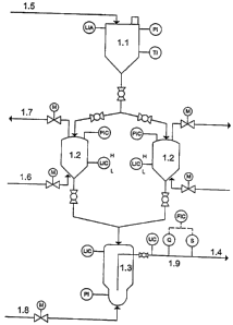
Figure l, the ground pulverized fuel is fed to the metering system 1.2, which
is shown in
Fig. 2. The pulverized fuel then is sent through the transport line 1.5 into
the supply
bunker 1.1 and is fed alternately to the pressurized sluices 1.2. The
pulverized fuel is
suspended in an inert gas such as nitrogen, for example, which is introduced
through the
line 1.6. After suspension, the pressurized pulverized fuel is fed to the
metering tank 1.3.
The pressurized sluice 1.2 is depressurized through the line 1.7 and can then
be loaded
again with pulverized fuel. There are three pressurized sluices that are
alternately filled
and depressurized. According to Fig. 3, three gasification reactors, each with
a metering
system, are provided for the gasification of 300 tons/hour of pulverized fuel.
A dense
fluidized bed is produced in the bottom of the metering tank 1.3, in which are
immersed
one or more dust transport lines 1.4, by feeding in a dry inert gas through
the line 1.8 in
an amount of 40,000 m3 i. H.lh, likewise nitrogen, for example, that serves as
the
transport gas.
In this example, three transport lines are provided in each case. The amount
of
pulverized fuel flowing in the transport line 1.4 is monitored, measured, and
regulated in
the system 1.9, and is fed to the burner of the gasification reactor 2 in Fig.
1 or Fig. 3.
The loading density is 250-420 kg/m3. The gasification reactor 2 is explained
in further
detail in Fig. 3. The pulverized fuel flowing through the transport lines 1.4
to the
gasification reactor in an amount of 300 tons/hour, is subjected to partial
oxidation at
1,450 °C in the gasification chamber 2.3 together with the oxygen in
the amount of
215,000 m3 i. H./h flowing in through the line 2.1. This results in 596,000 m3
i. H./h of
crude gas being formed, with the following composition:
H2 20.8 vol.%
CO 71.0 vol.%
COZ 5.6 vol.%
6
CA 02536715 2006-02-15
N2 2.3 vol.%
NH3 0.003 vol.%
HCN 0.002 vol.%
H2S 0.5 vol.%
COS 0.07 vol.%
The gasification chamber 2.3 is confined by a cooling shield 2.4 that consists
of a
water-cooled tube system welded gas-tight. The crude gas together with the
liquid slag
flows through the discharge opening 2.5 into the quenching cooler 3 (Fig. 1 ).
The
quenching cooler 3, connected rigidly to the gasification reactor 2 (Fig. 1 ),
is shown in
Fig. 3. It consists of a quenching chamber 3.1 constructed as an open space
with no
internals, into which water is sprayed through one or more rows of nozzles 3.2
and 3.3
to cool the hot crude gas. Condensate that occurs during the cooling of the
crude gas in
following system components is generally used to conserve fresh water. The
amount of
quenching water is about 500 m3/h. The crude gas saturated at 217 °C
has a steam
fraction of 57 vol.% at the outlet 3.4 from the quenching chamber. The slag is
collected
in a water bath 3.5 in the bottom of the quenching tank and is periodically
discharged
through the outlet 3.6. A wear shell 3.7 is provided to protect the
pressurized jacket from
erosion and corrosion.
The crude gas leaving the quenching chamber 3.1 through the outlet 3.4 in Fig.
3
then reaches the crude gas scrubber 4 in Fig. 1, designed as a Venturi
scrubber, and is
subjected to about 100 m3/h of wash water. Contained solids are removed from
the wash
water in the usual way and the water is fed back again to the Venturi
scrubber. To
remove fines < 20 pm in size and salt mists not separated in the Venturi
scrubber, the
water-washed crude gas is subjected to a partial condensation S according to
Fig. 1, with
the crude gas being chilled indirectly from 217 °C to 211 °C.
The finest dust and salt
particles are taken up by the steam condensing during the chilling and thus
removed
from the crude gas. The crude gas scrubber 4 and the partial condensation 5 to
remove
dust can be replaced by a separation step operating in wet or dry mode, in
which the
crude gas leaving the quenching chamber 3.1 is fed to a mechanical cleansing
step, for
example a centrifugal separator or a multiple tube filter. The crude gas
cleansed of solids
then has the following composition:
HZ 9.5 vol.%
7
CA 02536715 2006-02-15
CO 31.2 vol.%
C02 2.6 vol.%
NZ 1.1 vol.%
NH3 0.001vol.%
HCN 0.001vol.%
HZS 0.200vol.%
COS 0.03 vol.%
H20 54.60 vol.%
The purified wet crude gas amounts to 1,320,000 m3 NTP/h. It can be fed
directly to a crude gas converter or other treatment steps.
8
CA 02536715 2006-02-15
List
of
reference
symbols
used
1. Pneumatic metering system for
pulverized fuel
1.1 Bunker
1.2 Pressurized sluice
S 1.3 Metering tank
1.4 Transport line
1.5 Transport line for pulverized
fuel
1.6 Line for inert gas into 1.2
1.7 Pressure relief line
1.8 Line for inert gas into 1.3
1.9 Monitoring system
2. Reactor
2.1 Line for oxygen
2.2 Burner
2.3 Gasification chamber
2.4 Cooling shield
2.5 Discharge opening
3. Quenching cooler
3.1 Quenching chamber
3.2 Nozzle into 3
3.3 Nozzle into 3
3.4 Outlet from 3.1
3.5 Water bath
3.6 Discharge flow
3.7 Wear shell
4. Crude gas scrubber
5. Partial condensation
9