Note: Descriptions are shown in the official language in which they were submitted.
CA 02537019 2006-02-20
CLEANABLE MIXER DRIVER APPARATUS AND METIIOD
FIELD OF THEINVEITTION
[0001] The present invention relates generally to mixer systems, and more
particularly relates a cleanable drive arrangement for a mixer shaft of a
mixer
system.
BACKGROUND OF TI-IE INVENTION
100021 Mixers are in wide use in a number of industries, including for
example medical, pharmaceutical, food, and biotechnology industries. Many of
these mixers typically involve a shaft that extends into a vessel to drive a
number
of impellers which impart a mixing force to the material being mixed inside
the
vessel. Typically, the shaft is mounted to extend into the vessel by some form
of
mounting arrangement that also supports a drive motor.
[0003] In some types of mixing systems, a seal is located where the shaft
enters the vessel to contain material being mixed inside the vessel and also
to
prevent contaminants outside the vessel from entering the material to be
mixed.
Some industries have particularly high sanitary requirements in this regard.
In
response, a type of mixer drive has been developed in which a magnetic drive
is
provided having an internal canister to positively and completely seal the
vessel.
The motor on the outside of the canister drives a magnet rotor outside the
canister
and the shaft inside the vessel has a magnet rotor inside the canister. In
this type
of arrangement, the motor drives the shaft to drive the magnet rotor that is
located
outside the canister, the canister remains stationary and the magnet rotor for
the
impeller shaft is.driven by the rotating magnetic field induced by the outer
I.
CA 02537019 2012-08-17
magnetic rotor. Examples, of these types of magnetic drive systems can be
found
for example in U.S. Patent No. 5,368,390, to Gambrill et. al, issued November
29, 1994, which is hereby incorporated in its entirety by reference, and 'U.S.
Patent No. 5,427,450, to Gambrill, issued June 27, 1995, which is also hereby
incorporated in its entirety by reference.
100041 Thc arrangement disclosed U.S. Patent No. 5,427,450 provides
many advantages, including the ability to flush and clean the components which
are located inside of the canister in some situations without needing
disassembly
of the drive system. However, although the system described in U.S. Patent No.
5,427,450 is very advantageous it is still desired to have improvements to
this
type Of system, such as for example providing a simpler system using fewer
parts,
and the provision of a system which can if desired provide an even more
sanitary
arrangement in some applications after it has been cleaned.
[00051 Accordingly, there is a need in the art, for an even improved
magnetic mixer drive system, which can be cleaned in place.
SUMMARY OF THE INVENTION
[00061 The foregoing needs are met, to a great extent, by the present
invention, wherein in one aspect an apparatus is provided that in some
embodiments provides an even improved magnetic mixer drive system, which can
be cleaned in place.
2
CA 02537019 2012-08-17
[0007] According to the present invention, there is provided a drive
system for driving a mixer impeller shaft in a vessel, the drive system
comprising:
a motor;
an outer magnet rotor driven by the motor and a gear reducer;
a bearing housing mountable to the vessel;
a drive shaft rotatable in the bearing housing;
an inner magnet rotor connected to the drive shaft;
a manifold plate connected to the bearing housing;
a canister connected to the manifold plate;
a chamber defined in the bearing housing and having an inlet port for
directing fluids into the chamber;
a plurality of first ports through the manifold plate for providing fluid
communication from the chamber to the inside of the canister; and
a plurality of second ports through the inner magnet rotor for providing fluid
communication from the inside of the canister through the inner magnet rotor,
whereby a fluid path is provided from the chamber through the first ports,
around the inner magnet motor, and through the second ports of the inner
magnet
rotor, which fluid paths is sealed from the environment from the canister.
[0008] According to the present invention, there is also provided a drive
system for driving a mixer impeller shaft in a vessel, the drive system
comprising:
an outer magnet rotor;
power operated driving means for driving the outer magnet rotor;
a bearing housing means mountable to a vessel;
a drive shaft rotatable in the bearing housing means;
an inner magnet rotor connected to the drive shaft;
manifold means connected to the bearing housing;
containing means connected to the manifold plate;
a chamber defined in the bearing housing and having means for directing
fluids into the chamber;
a plurality of first ports through the manifold plate for providing fluid
communication from the chamber to the inside of the containing means; and
3
CA 02537019 2012-08-17
=
a plurality of second ports through the inner magnet rotor provide fluid
communication from the inside of the containing means through the inner magnet
rotor,
whereby a fluid path is provided from the chamber through the first ports,
around the inner magnet motor, and through the second ports of the inner
magnet
rotor, which fluid path is sealed by the environment from the containing
means.
[0009] According to the present invention, there is also provided a
method of cleaning a drive system for driving mixer impeller shaft in a
vessel,
comprising:
providing a drive system comprising:
a motor;
an outer magnet rotor driven by the motor;
a bearing housing mountable to the vessel;
a drive shaft rotatable in the bearing housing;
an inner magnet rotor connected to the drive shaft;
a manifold plate connected to the bearing housing;
a canister connected to the manifold plate;
a chamber defined in the bearing housing and having an inlet port for
directing fluids run into the chamber;
a plurality of first ports through the manifold plate for providing fluid
communication from the chamber to the inside of the canister; and
a plurality of second ports through the inner magnet rotor provide fluid
communication from the inside of the canister through the inner magnet rotor,
whereby a fluid path is provided from the chamber through the first ports,
around the inner magnet motor, and through the second ports of the inner
magnet
rotor, which fluid paths is sealed from the environment from the canister, and
forcing a cleaning or rinsing fluid to the inlet port to clean the drive
system.
[0010] There has thus been outlined, rather broadly, certain embodiments
of the invention in order that the detailed description thereof herein may be
better
understood, and in order that the present contribution to the art may be
better
4
CA 02537019 2012-08-17
appreciated. There are, of course, additional embodiments of the invention
that will
be described below.
[0011] In this respect, before explaining at least one embodiment of the
invention in detail, it is to be understood that the invention is not limited
in its
application to the details of construction and to the arrangements of the
components
set forth in the following description or illustrated in the drawings. The
invention is
capable of embodiments in addition to those described and of being practiced
and
carried out in various ways. Also, it is to be understood that the phraseology
and
terminology employed herein, as well as the abstract, are for the purpose of
description and should not be regarded as limiting.
[0012] as such, those skilled in the art will appreciate that the conception
upon which this disclosure is based may readily be utilized as a basis for the
designing of other structures, methods and systems for carrying out the
several
purposes of the present invention.
BRIEF_ DESCRIPTION OF TIIE DRAWINGS
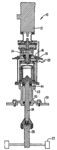
100131 FIG. 1 is a cross-sectional view illustrating a mixer driver
assembly.
[0014J FIG. 2 is a detailed cross-sectional view showing the central drive
components of the preferred embodiment of FIG. 1.
ig TAILED DESCRIPTIQN
[0015) Some embodiments of the present invention provide an improved
majestic mixer drive system which can be cleaned in place. Preferred
embodiments will now be described with references to the drawing figures in
which like reference numerals refer to like parts throughout.
5
CA 02537019 2006-02-20
[00161 FIG. 1 is a cross-sectional view illustrating a magnetic mixer drive
assembly 10, including a motor 12 that drives a motor shaft 14. A motor 12 is
supported by a motor mount 16, which is mounted by a plate 18 to the top of a
pedestal 20. The pedestal 20 surrounds the lower part of the motor shaft 14,
as
well as other components which will be explained later, and at its lower end
the
pedestal 20 is mounted to the top of a bearing housing 22. The bearing housing
22 support drive shaft 24 by means of bearing which are described in more
detail
below. The drive shaft 24 extends through the bearing housing 22 and projects
downwardly below the bearing housing 22.. The drive shaft 24 may have
impellers radially extending therefrom, or maybe connected by a coupling to an
impeller shaft 26 which has impellers 27 extending radially therefrom. The
pedestal 22 is mounted at its lower end to opening at the top of the vessel
28,
which vessel 28 provides a container for the fluid or other material that is
to be
mixed by the impellers 27. The impeller shaft 26 may have onc or several sets
of
radially extending impellers along its length keeping with the particular
mixing
requirements involved.
(00171 As will be described in more detail below, the motor 12 rotatably
drives the gear reducer shaft 14, and a magnetic coupling between the reducer
shaft 14 and the drive shaft 28 causes those two shafts to be rotationally
coupled
and rotate together with each other, so that in effect, the motor 12 provides
rotational force to the drive shaft 14, and also the impeller shaft 26.
Details of
this coupling are illustrated in FIG. 2.
[0018) Turning now to FIG. 2, the top of the drawing illustrates the lower
part of the mount 16 mounted by the plate 18 onto the top of the pedestal 20.
The
reducer shaft 14 extends somewhat below the mount 16 and is connected by a
6
CA 02537019 2006-02-20
bolt and other suitable connecting mechanism to a coupling rotor collar 30
that
has attached to it an outer magnet rotor 32. The outer magnet rotor 32
supports a
plurality of magnets 34, which are spaced slightly outward from the outside
edge
of a canister 36. Inside the canister 36 is disposed an inner magnet rotor 38
which
support a plurality of outward facing magnets 40, which are spaced radially
inward from the inside surface of the canister 36. An inner rotor bolt 42
attaches
the inner magnet rotor 40 to a drive shaft 24. The drive shaft 24 is
rotationally
supported in the bearing housing 22 by upper bearings 44, and lower bearings
45
(see FIG.1).
(0019] Returning to FIG. 2, the above described arrangement provides a
magnetically coupled drive between the reducer shaft 14 and the drive shaft
24.
The canister 36 is a dome shaped hollow cylinder closed at its top end, with
its
open lower end mounted directly to a manifold plate 46. The manifold plate .46
in
turn is mounted directly to the top of the bearing housing 22. Thus, it can be
appreciated that a positive enclosure is formed by the canister 36, manifold
plate
46, and bearing housing 22, the inside of which enclosure is exposed to thc
internal volume of the vessel 28, and the outside of which is exposed to the
ambient environment, although it is generally covered by the pedestal 20,
plate 18
and motor mount 16, with the outer magnetic motor 32, collar 30, as act also
being outside the canister 36.
(0020] A cleaning flow path arrangement is provided in the preferred
embodiment. In the illustrated embodiment, an inlet fitting 50 leads into a
= circumferential chamber 52 in the bearing housing 22. A plurality
of manifold
ports 54 are spaced circumferentially and penetrating through the manifold
plate
46 as shown. The ports 54 thus provide for fluid movement from the chamber 52
7
CA 02537019 2006-02-20
up into the space inside the canister 36 and surrounding the inner magnet
rotor 38.
The inner magnet rotor has a curved top end 56 as shown. The inner rotor bolt
42
has a domed top surface 58. The inner magnet rotor 38 further has a plurality
of
circumferentially arranged ports 60, which extends from the interior of the
inner
magnet rotor 38 through the lower part of the inner magnet rotor 38 and into a
space located just above bearings 44.
[0021] During operation, the inlet fitting 50 can be sealed off by any
conventional sealing arrangement, in which case the above described fluid
passage area is sealed from the external environment, and thus the material to
be
mixed is also sealed from the external environment.
[0022] When mixing has been completed, it is sometimes desired to clean
and/or flush the mixer driver's arrangement illustrated in FIG. 2 and such a
flushing can be accomplished as follows. Any cleaning or rinsing fluid,
whether
it be water or a chemical cleaning fluid, can be provided to the inlet fitting
50
using a sanitary fitting. The cleaning or rinsing fluid is provided under a
positive
pressure and will flow into the chamber 52 and then upward through the ports
54.
The majority of this fluid will be urged upward by the fluid pressure through
the
space between the inner magnet rotor 40 and the inside of the canister 36 and
will
flow upward over the rounded top end of the inner magnet rotor 38. The fluid
will then partially or completely fill the area inside the inner magnet rotor
40 and
will travel downward through the length of the ports 60, thus being provided
to
the top surface of the beatings 44 and washing through the bcarings 44 and
= continuing down the space between the drive shaft 24 and the bearing
housing 22,
until it contacts the lower set of bearing and then flows over the lower set
of
bearings and out through a space provided between the bottom of the bearing
8
CA 02537019 2006-02-20
housing 22 and the outside of the drive shaft 24, and thus into the vessel
itself. In
this way, a one flushing type flow can be provided at the inlet fitting and
will
wash over all the internal exposed surfaces of the drive arrangement,
including
bearing 44 and the lower bearing 45, before the flushing material is provided
into
the vessel area.
[0023] It is notcd that a spacing A is provided between a lower beveled
edge of the inner magnet rotor 38 and beveled inner edge of the manifold plate
46. This spacing is necessary to permit rotation of the inner magnet rotor 38
relative to the stationary manifold plate 46. However, as this spacing is
relatively
small in some embodiments, some of the cleaning or rinsing material will flow
through this space but the majority of the cleaning OT rinsing material will
still be
forced upward and over the inner magnet rotor 38.
100241 The surfaces of the illustrated embodiment are specially designed
to have desirable cleaning properties. For example, as noted above the top of
the
inner magnet rotor 56 has a curved configuration without any planar or
horizontal
surfaces. Similarly, the top of the inner rotor bolt 42 has a dome surface 58
with
slightly sloping shoulders 59 and the lower inner region of the inner magnet
rotor
38 in the area near the port 60 has a concaved curved profile. Further, the
top of
the manifold plate 36 in the region of the port 54 has a downward sloping, non-
horizontal, arrangement By virtue of all these features, it can be seen that
the
cleaning flow area has no planar horizontal surfaces, in some embodiments,
provides the advantage of reducing deposits of fine materials or drying of
tiny
droplets of cleaning material residue.
100251 The materials are also selected to interact well with the cleaning
and or flushing fluids, for example, the bearing housing 22, manifold plate
46,
9
CA 02537019 2006-02-20
canister 36, and inner magnet rotor 38, as well as the inner rotor bolt 42 are
typically made of stainless steel. Further, the bearings 44 and 45 are of a
type
using ceramics so that they do not require lubrication and are not damaged by
cleaning and/or flushing solutions.
[0026] One benefit of the example embodiment illustrated in FIG. 2, is
that a relatively few number of components are involved, and accordingly a
relatively small number of surface to surface seals needs to be accomplished
to
maintain sealing of the fluid flow path. It is notcd that 0-rings 90 are used
(1) to
seal the inner rotor bolt 42 to the inner magnet rotor 38, (2) to seal the
manifold
plate 36 to the canister 36, (3) in two places to seal the bearing housing 22
to the
manifold plate 36 around the chamber 52, and (4) and in two places to seal the
bearings 44. This relatively economical use of relatively few o-rings
accomplishes complete sealing of the inner driver arrangement from the outer
environment and this provides an advantage of the prior art.
[0027] Although the above description refers to some extent to horizontal
and vertical directions, it will be appreciated that the embodiments Of the
invention need not be vertical in orientation, and need not be at the top of a
vessel. Further, accessory features maybe provided such as a tachometer plate
70
and a tachometer pick-up 72 to measure drive speed, as well as a guide rod 74
which may facilitate orientation and aid in removal of the drive, by centering
the
coupling as to not come in contact with the canister.
[0028] The preferred embodiments of the arrangement described herein
may be suitable for any of a variety of cleaning and flushing procedures. In
one
preferred cleaning procedure several fluids are forced through the system for
approximately one half hour each between batches of mixer operations. Such a
10
CA 02537019 2006-02-20
preferred sequence includes (1) washing with distilled water, (2) flushing
with
caustic solution, (3) flushing with distilled water, (4) flushing with acid,
(5)
drying with air, and (6) applying steam to heat the internal =faces to
approximately 275 degrees Fahrenheit.
[0029) As has been described above, one of the beneficial qualities of the
illustrated preferred embodiment is that none of the parts that contact these
cleaning fluids drive system has a flat horizontal surface which might tend to
retain particles or residue. Further, due to the fairly abrupt change in size
between the top of the chamber 52 and the relatively much smaller port 54, if
the
cleaning or rinsing solution has large contaminants in it; such contaminants
typically do not travel through the small ports 54 and thus remain within the
large
chamber 52, from which they are typically fairly easy to remove from the inlet
fitting 50, without requiring major disassembling of the apparatus. Further,
if
these large contaminants can not be removed via the inlet fitting 50, the
bolts 99
which attach the canister 36 and manifold plate 46 to the bearing house 22 can
be
removed thus providing easy access to the chamber 52 via a very simple
disassembly step.
100301 The many features and advantages of the invention arc apparent
from the detailed specification, and thus, it is intended by the appended
claims to
cover all such features and advantages of the invention which fall within the
true
spirit and scope of the invention. Further, since numerous modifications and
variations will readily occur to those skilled in the art, it is not desired
to limit the
invention to the exact construction and operation illustrated and described,
and
accordingly, all suitable modifications and equivalents maybe resorted to,
falling
within the scope of the invention.
11