Note: Descriptions are shown in the official language in which they were submitted.
CA 02537025 2006-02-20
Partial-Length Indwelling Urinary Catheter
and Method Permitting Selective Urine Discharge
Cross-Reference to Related Application
This is a continuation-in-part of U.S. patent application for a Partial-Length
Indwelling Prostatic Catheter Using Coiled Inflation Tube as an Anchor and
Methods of Draining Urine and Flushing Clots, Serial No. 10/665,742, filed on
September 17, 2003, filed by some of the inventors hereof and assigned to the
assignee hereof. This is also related to U.S. patent application for a Urinary
Catheter and Method with Increased Resistance to Obstructions, Serial No.
10/921,356 filed August 18, 2004. The subject matter of these prior patent
applications is hereby incorporated by this reference.
Field of the Invention
This invention relates to a partial-length indwelling urinary catheter and the
~5 use of such a urinary catheter. More particularly, the present invention
relates to a
new and improved partial-length indwelling catheter that permits the user to
selectively open a passageway for the drainage of urine through an obstructed
prostatic urethra or a constricted external urinary sphincter muscle under
conditions of urinary tract retention and to accommodate a moderate range of
2o differences in position within the urinary tract.
Background of the Invention
Prostate problems, such as benign prostate hyperplasia (BPH) and
malignant prostate cancer, are common occurrences among older men. The
effects of these diseases are generally accompanied by swelling or enlargement
of
25 the prostate gland. Apart from the life-threatening aspects of malignant
prostate
cancer, the everyday symptoms and effects of these diseases are usually
troublesome. One such problem relates to the ability to control and achieve
normal urine discharge. When the prostate gland enlarges to the extent that it
obstructs the prostatic urethra through the prostate gland, considerable
difficulties
CA 02537025 2006-02-20
arise in discharging urine at will. Such difficulties are typically referred
to as urinary
tract retention. Urinary tract retention can be either acute or chronic.
Surgical treatments are available for relieving urinary tract retention caused
by an obstruction of the prostatic urethra. One such treatment is a
transurethral
s resection of the prostate (TURP). A TURP procedure involves surgically
resecting
tissue from the prostate gland to eliminate or reduce the obstruction or
restriction.
Surgical operations offer a high probability of an excellent clinical outcome,
but
they are associated with a high degree of morbidity. Alternative treatments
with
milder side-effects include transurethral microwave thermotherapy (TUMT),
radio
frequency needle ablation (TUNA), interstitial laser and hot water induced
thermotherapy (WIT). All of these alternative treatments involve heating the
obstructive prostatic tissue until the tissue is destroyed or damaged.
Thereafter,
the destroyed or damaged tissue sloughs off, is absorbed in the body, and
otherwise results in an enlargement of the urinary passageway through the
15 prostate gland. The enlargement of the urinary passageway through the
prostate
gland eliminates or relieves the obstruction and permits better urine flow.
Another form of urinary tract retention results from a weak bladder. A weak
bladder condition results when the muscle that surrounds the bladder does not
contract and compress the bladder sufficiently to create enough fluid pressure
on
2o the urine within the bladder to dilate the orifice in the external urinary
sphincter
muscle in males and establish a substantial flow of urine into a urinary canal
which
leads to the exterior of the body. Males have two urinary sphincter muscles:
an
internal urinary sphincter muscle at the bladder neck or junction of the
urethra with
the bladder, and an external urinary sphincter muscle at the downstream point
25 where the prostatic portion of the urethra exits from the prostate gland
into the
urinary canal through the penis.
Under normal conditions when urine is not discharged, both urinary
sphincter muscles are constricted to close their orifices and prevent the flow
of
urine through the urethra. The muscle surrounding the bladder relaxes while
the
3o bladder is naturally filled with urine. To urinate, the muscle surrounding
the
bladder contracts automatically to create fluid pressure on the urine within
the
2
CA 02537025 2006-02-20
bladder. Pressure from the urine is applied to the constricted internal
urinary
sphincter muscle and is sensed by the brain. The orifice through the internal
urinary sphincter muscle is voluntarily dilated to pass urine from the bladder
into
the prostatic urethra. However, if the muscle surrounding the bladder does not
apply sufficient pressure on the urine, there is insufficient fluid pressure
on the
normally-constricted external urinary sphincter muscle to cause it to dilate
or open.
The external urinary sphincter muscle opens in response to the fluid pressure
conducted through the prostatic urethra. Under circumstances of insufficient
fluid
pressure, the external urinary sphincter muscle will not dilate or will dilate
only
slightly, thereby restricting or preventing urine discharge. The inability to
empty the
bladder of urine can lead to serious health problems and death.
In those cases where the diseased prostate gland cannot be treated by a
TURP or by a heat treatment, and in those cases where a weak bladder prevents
or restricts urine flow, it is necessary for a mechanical fluid passageway to
be
established from the bladder. The most prevalent mechanical way to open the
external urinary sphincter muscle is to insert a full-length catheter. The
full-length
urinary catheter extends from the exterior opening of the penis through the
entire
length of the urinary tract into the bladder. The full-length catheter forms a
tubular
stent which permanently holds the urinary sphincter muscle open, thereby
2o preventing it from closing and restricting the flow of urine. In some
cases, the
patient is taught to insert a full-length catheter whenever urination is
necessary. In
other cases, where the patient cannot insert the full-length catheter himself,
medical personnel insert an indwelling full-length catheter in the urinary
tract where
it must remain. In some cases, the full-length catheter must be used for the
2s remainder of the individual's life.
TURP and the prostate heat treating techniques cause temporary side
effects, for example inflammation and swelling of the prostate. The swelling
may
be so great as to obstruct the passage of urine through the surgically-treated
prostate gland. Direct contact from urine can aggravate the inflammation and
3o increase the risk of infection to the viable but nevertheless raw, tender
and swollen
tissue of the prostate gland after a TUMT or a heat treatment. These side
effects
3
CA 02537025 2006-02-20
of a TUMT or heat treatment usually require the patient to use an indwelling
urine
drainage catheter for a few days up to several weeks following the procedure
to
permit urination while the swelling subsides and the tissue of the prostate
gland
heals or stabilizes.
s Because a full-length urinary drainage catheter provides a continuously
open interior urine flow passageway between the bladder and the exterior
opening
of the penis, a clamp or other mechanical valve must be used at the exterior
of the
body to control the urine flow from the catheter. The clamp or valve is opened
to
drain the urine from the bladder and is closed to terminate urine flow from
the
bladder. Alternatively, a reservoir may be attached to the end of the catheter
to
collect the discharged urine, in which case the mechanical valve or clamp may
not
be used.
The extension of the catheter out of the exterior opening of the penis, the
presence of the clamp or valve and the presence of the reservoir cause
discomfort,
are awkward to deal with and may be embarrassing. The full-length urinary
catheter may create limitations from a social standpoint and almost always
creates
quality of life issues which must be confronted. Sexual activity is
impossible. An
increased risk of infection also results.
Because of the quality of life and social issues associated with full-length
2o urinary catheters, partial-length indwelling catheters have been developed.
Partial-
length indwelling catheters typically extend from the bladder partially along
the
prostatic urethra, but not along the entire length of the urinary tract from
the
bladder to the exterior opening of the penis. The typical partial-length
indwelling
catheter extends from the bladder through the prostatic urethra to an upstream
2s position adjacent to the external urinary sphincter muscle. The reduced
length
permits the external urinary sphincter muscle to control urine flow in a more
natural
manner, while still bypassing most of the urine flow around the swollen,
obstructed
or raw prostate gland.
Keeping a partial-length indwelling catheter in the proper position is
3o essential. The short length may allow the catheter to move completely into
the
4
CA 02537025 2006-02-20
bladder or move out of the bladder into the urethra and the urinary canal.
Either
type of unintended movement may require serious medical intervention to
correct.
A partial-length urinary catheter typically uses an inflatable balloon or
other
form of anchor at its end which is within the bladder. The balloon or anchor
is
s expanded or enlarged within the bladder. The expanded or enlarged balloon or
anchor contacts the bladder neck at the entrance to the urethra and prevents
the
partial-length catheter from moving out of the bladder and into the urethra.
Another downstream anchor is typically attached to the partial-length of
catheter to
prevent the catheter from moving in the opposite direction into the bladder.
The
downstream anchor is positioned downstream from the external urinary sphincter
muscle and is connected to the partial-length catheter with a short length of
thread-
like material. The thread-like material extends through the orifice of the
external
urinary sphincter muscle between the downstream anchor and the partial-length
indwelling catheter. The catheter and the downstream anchor are therefore
15 positioned on opposite sides of the external urinary sphincter muscle. The
normal
constricted state of the external urinary sphincter muscle restrains the
downstream
anchor and prevents the partial-length catheter from moving into the bladder.
The external urinary sphincter muscle is able to constrict around the thread-
like material to stop urine flow and is able to dilate to permit the flow of
urine. In
2o this matter, the natural functions of the external urinary sphincter muscle
control
the discharge of urine. The clamps, valves and reservoirs used with a full
length
catheter, as well as the self-consciousness, embarrassment and social problems
and difficulties caused by these devices, are avoided entirely by using a
partial-
length indwelling catheter.
2s Despite the advantages and benefits of a partial-length indwelling
catheter,
a partial-length indwelling catheter is not effective to overcome the urine
discharge
problems caused by a weak bladder. The partial-length indwelling catheter
terminates upstream of the external urinary sphincter muscle. Although the
fluid
pressure within the bladder is communicated through the partial-length
indwelling
3o catheter to the external urinary sphincter muscle, the relatively low fluid
pressure
from the weak bladder is insufficient to cause the external urinary sphincter
muscle
CA 02537025 2006-02-20
to open. It is for this reason that a partial-length indwelling catheter is
not effective
in permitting control over urine drainage under weak bladder conditions. A
full-
length urinary drainage catheter is required for urine drainage under weak
bladder
conditions and under conditions caused by some neurogenic disorders.
A partial-length indwelling catheter may also be of limited prophylactic value
after a TUMT or heat treatment. The downstream end of the partial-length
indwelling catheter may not immediately adjoin the external urinary sphincter
muscle, but instead, because of differences in physiological length of the
prostatic
urethra in different males, may terminate a short distance before the external
urinary sphincter muscle. This small gap between the downstream end and the
external urinary sphincter muscle may swell to the point where it restricts
urine flow
through the prostate gland after a TUMT or other heat treatment. Similarly,
the
enlargement of the prostate gland due to BPH or other disease may also extend
into the gap between the downstream end of the partial-length indwelling
catheter
and the external urinary sphincter muscle. Under such obstructive
circumstances,
the partial-length indwelling catheter is not effective in permitting urine
discharge,
thereby requiring a full-length urinary drainage catheter to be used instead
of the
more desirable partial-length indwelling catheter.
Summary of the Invention
2o The invention overcomes the problems of urine discharge under conditions
of urinary tract retention due to a prostatic urethra obstruction arising from
swelling
of the prostate gland caused by disease or after surgical treatment, or
arising from
a weak bladder or neurogenic disorder, as well as under conditions of moderate
differences in position and urinary tract physiology. The benefits and other
2s desirable aspects of the invention allow the user to discharge urine at
will and
avoid the need to use a less-desirable full-length catheter.
The present invention involves a method and a partial-length indwelling
catheter for draining urine in a male human from the bladder through the
prostate
gland and through the orifice in the external urinary sphincter muscle and
into the
3o urinary canal which ends at the exterior opening of the urinary canal.
6
CA 02537025 2006-02-20
In general terms, the method involves positioning a partial-length indwelling
catheter in a normal position which a distal end of the catheter is located
within the
bladder and a proximal end of the catheter is located at a position distally
adjacent
to and upstream of the external urinary sphincter muscle, anchoring the
catheter to
resist proximal movement from the normal position, conducting urine from the
bladder through an interior passageway of the catheter which extends between
the
distal end and the proximal end of the catheter, and selectively displacing
the
proximal end of the catheter in a proximal and downstream direction from the
normal position through an orifice in the external urinary sphincter muscle to
~o conduct urine from the bladder through the interior passageway within the
catheter
and through the external urinary sphincter muscle into the urinary canal,
thereby
draining or discharging urine from the bladder.
The method may also involve some or all of the following features. The
proximal end of the catheter is displaced in the distal direction through the
orifice of
the external urinary sphincter muscle after urine has been drained from the
bladder. The normal constriction of the orifice through the external urinary
sphincter muscle is relied on to prevent urine drainage from the distal end of
the
catheter into the urinary canal while the catheter is in the normal position.
A
control cord is extended from the catheter through the orifice of the external
urinary
2o sphincter muscle and through the urinary canal to a position outside of the
exterior
opening, and the control cord is moved to selectively displace the proximal
end of
the catheter in a proximal direction from the normal position through the
orifice of
the external urinary sphincter muscle. The proximal end of the catheter is
displaced in a proximal direction from the normal position by moving the
entire
catheter in the proximal direction or by moving an extendable proximal end
portion
of the catheter in the proximal direction. The catheter is anchored to resist
distal
as well as proximal movement from the normal position.
In general terms, the partial-length indwelling catheter has a main body with
a distal end and a proximal end. The main body has a length sufficient to
establish
3o a normal position in which the distal end is within the bladder and the
proximal end
is distally adjacent to and upstream of the external urinary sphincter muscle.
The
7
CA 02537025 2006-02-20
main body defines an interior passageway extending from the distal end to the
proximal end. The interior passageway communicates with the interior of the
bladder. A distal anchor element is connected to the distal end of the main
body.
The distal anchor element is expandable in size to contact the bladder neck
s adjacent to the opening of the prostatic urethra into the bladder to
restrain the main
body against proximal movement from the normal position. A control element is
connected at a distal end to the main body and has a length sufficient to
extend
through the orifice of the external urinary sphincter muscle and through the
urinary
canal to a position outside the exterior opening. The control element
transfers
force from its proximal end to the main body to selectively displace the
proximal
end of the catheter in a proximal direction from the normal position through
the
orifice of the external urinary sphincter muscle and thereby conduct urine
from the
bladder through the interior passageway and into the urinary canal at a
position
proximal and downstream of the external urinary sphincter muscle.
15 The partial-length indwelling catheter may also include some or all of the
following features. The control element may include a control cord which is
connected to the main body to transfer pulling force that is sufficient to
compress
the distal anchor element against the bladder neck and move the entire
catheter in
the proximal direction to thereby displace the proximal end of the catheter
from the
2o normal position in a proximal direction through the orifice of the external
urinary
sphincter muscle. The distal anchor element may include an inflatable balloon
which can be inflated with fluid, and the inflatable balloon is compressed
against
the bladder neck when the entire catheter is moved in the proximal direction
to
thereby displace the proximal end of the catheter from the normal position in
a
25 proximal direction through the orifice of the external urinary sphincter
muscle. The
force of compressing the inflatable balloon against the bladder neck to
displace the
proximal end of the catheter in the distal direction through the orifice of
the external
urinary sphincter muscle returns the main body to the normal position after
releasing the force on the control cord. The main body may include an
extendable
3o proximal end portion. The control element is connected to the extendable
proximal
end portion to move the extendable proximal end portion in a proximal
direction
8
CA 02537025 2006-02-20
from the normal position through the orifice of the external urinary sphincter
muscle. A bias element is connected between the extendable proximal end
portion
and the main body to return the extendable proximal end portion from extending
through the orifice of the external urinary sphincter muscle upon ceasing
application of pulling force on the control cord. The extendable proximal end
portion of the main body may comprise a tube member which is telescopically
movable relative to the main body or a flexible sleeve member which is
expandable
relative to the main body. The control element or cord transfers pulling force
which
is sufficient to move the extendable proximal end portion of the main body in
the
proximal direction relative to the main body and through the orifice of the
external
urinary sphincter muscle. A proximal anchor element is connected to the main
body and is located at a position on the proximal side of the external urinary
sphincter muscle when the distal anchor element contacts the bladder neck. The
proximal anchor element restrains the main body against distal movement from
the
normal position.
Additional features of the catheter may include some or all of the following.
The distal anchor element comprises an inflatable balloon which is attached to
the
main body. An inflation tube is connected to the main body and has a length
sufficient to extend from the main body through the orifice in the external
urinary
2o sphincter muscle. The inflation tube communicates fluid for expanding the
balloon.
A proximal anchor element of the catheter includes a coiled section of the
inflation
tube within the urinary canal at a position proximal and downstream of the
external
urinary sphincter muscle when the orifice through the external urinary
sphincter
muscle is constricted.
Another aspect of the invention is a method of diagnosing urinary tract
retention in a male human caused by one of either a blockage in a prostatic
urethra or by a weak bladder. The method comprises positioning a partial-
length
indwelling catheter within the prostatic urethra to establish fluid
communication
from the bladder through an interior passageway of the catheter to a position
at the
3o proximal end of the catheter distally adjacent to the sphincter muscle,
flowing urine
through the catheter, determining whether urine flow from the exterior opening
is
9
CA 02537025 2006-02-20
greater with the catheter positioned in the prostatic urethra compared to the
urine
flow when the catheter is not positioned in the prostatic urethra, diagnosing
a
blockage in the prostatic urethra if the urine flow with the catheter
positioned in the
prostatic urethra is significantly greater than the urine flow when the
catheter is not
s positioned in the prostatic urethra, and diagnosing a weak bladder if the
urine flow
with the catheter positioned in the prostatic urethra is not substantially
different
from the urine flow when the catheter is not positioned in the prostatic
urethra.
The diagnosis of a weak bladder may be verified by selectively displacing the
proximal end of the catheter in a proximal direction through the orifice of
the
external urinary sphincter muscle while maintaining the interior passageway in
fluid
communication with urine in the bladder, and determining whether urine flow
from
the exterior opening is greater with the proximal end of the interior
passageway
extending through the orifice of the external urinary sphincter muscle. If so,
the
diagnosis of a weak bladder is confirmed. This diagnostic method may also be
used to rule out or to implicate certain neurogenic disorders of the external
urinary
sphincter muscle which prevent that muscle from dilating or constricting under
appropriate urination conditions.
A more complete appreciation of the scope of the present invention and the
manner in which it achieves its significant improvements can be obtained by
2o reference to the following detailed description of presently preferred
embodiments
taken in connection with the accompanying drawings, which are briefly
summarized below, and by reference to the appended claims.
Brief Description of the Drawings
Fig. 1 is a perspective view of a partial-length indwelling prostatic catheter
2s which incorporates the present invention, shown attached to an insertion
tool and
used with a syringe.
Fig. 2 is an enlarged perspective view of the catheter shown in Fig. 1 with
the insertion tool removed and with a balloon of the indwelling catheter
expanded.
Fig. 3 is an enlarged longitudinal cross-section view of the catheter shown in
3o Fig. 2, taken substantially in a longitudinal axial plane with a portion
broken out.
CA 02537025 2006-02-20
Fig. 4 is an enlarged transverse cross-section view taken substantially in the
plane of line 4-4 of Fig. 1.
Fig. 5 is an enlarged partial longitudinal axial cross-section view of a
separable connection of the indwelling catheter-insertion tool assembly shown
in
s Fig. 1, taken substantially in the plane of line 5-5 shown of Fig. 1.
Fig. 6 is a perspective view of the indwelling catheter and a portion of the
insertion tool shown in Fig. 1, shown inserted within a urethra, an external
urinary
sphincter muscle, a prostatic urethra and a bladder of a urinary tract of a
male
human being, with the physiology generally illustrated in cross-section.
Fig. 7 is an illustration similar to Fig. 6 showing the balloon inflated
within
the bladder.
Fig. 8 is an illustration similar to Figs. 6 and 7 showing separation of the
insertion tool from the indwelling catheter.
Fig. 9 is an illustration similar to Figs. 6-8 showing use of the indwelling
~ 5 catheter when discharging urine through an orifice of the external urinary
sphincter
muscle.
Fig. 10 is an enlarged longitudinal cross-section view of another form of a
partial-length indwelling catheter of the present invention which uses a
telescoping
or extendable tube member.
2o Fig. 11 is a partial view of the indwelling catheter shown in Fig. 10,
showing
the telescoping tube member in an extended position.
Fig. 12 is an illustration similar to Fig. 9, showing use of the indwelling
catheter shown in Figs. 10 and 11 when discharging urine through an orifice of
the
external urinary sphincter muscle.
25 Fig. 13 is an enlarged longitudinal cross-section view of another form of a
partial-length indwelling catheter of the present invention which uses an
extendable and flexible sleeve member.
Fig. 14 is a partial view of the indwelling catheter shown in Fig. 13, showing
the flexible sleeve member in an extended position.
11
CA 02537025 2006-02-20
Fig. 15 is an illustration similar to Figs. 9 and 12, showing use of the
indwelling catheter shown in Figs. 13 and 14 when discharging urine through an
orifice of the external urinary sphincter muscle.
Fig. 16 is an illustration similar to Figs. 12 and 15, additionally showing
the
use of a flushing tube with the indwelling catheters shown in Figs. 10 and 13.
Fig. 17 is a flow chart showing the use of a partial-length indwelling
catheter
for diagnosing a prostatic urethra obstruction or a weak bladder condition.
Detailed Description
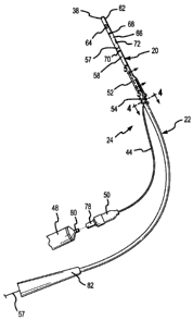
One embodiment of a partial-length indwelling catheter 20 which
incorporates the present invention is shown in Fig. 1. The indwelling catheter
20 is
connected to an insertion tool 22 to form a catheter-tool assembly 24, which
allows
the catheter 20 to be inserted into a urinary tract of a human being, such as
a
urinary tract 26 of a male human shown in Fig. 6. Once inserted, the insertion
tool
22 is disconnected or separated from the indwelling catheter 20 to leave the
~ 5 catheter 20 dwelling or remaining within the urinary tract, to extend
through a
prostatic urethra 28 within a prostate gland 30 of a male human being shown in
Figs. 6-9, 12 and 15. In its indwelling use position shown in Fig. 8, the
catheter 20
conducts urine from a bladder 32 through the prostatic urethra 28 within the
prostate gland 30 to a position slightly upstream of an external urinary
sphincter
2o muscle 34.
The indwelling catheter 20 is pushed into the urinary tract 26 with the
insertion tool 22 until a distal end 38 of the indwelling catheter 20 enters
the
bladder 32 as shown in Fig. 6. A balloon 40 on the indwelling catheter 20 is
inflated with fluid conducted through an inflation passageway 42 of an
inflation
25 tube 44 until the balloon 40 is larger in diameter than a neck 46 of the
bladder 32
surrounding the prostatic urethra 28, as shown in Fig. 7. The inflation fluid
may be
gas, such as air, or liquid such as saline solution. The balloon 40 is
preferably
inflated from an inflation pump, such as a syringe 48, which is connected to a
valve
assembly 50 at the end of the inflation tube 44 (Fig. 1 ). Once the balloon 40
has
3o been inflated, the insertion tool 22 is pulled backwards until the inflated
balloon 40
is seated on the bladder neck 46. When seated on the bladder neck 46, the
12
CA 02537025 2006-02-20
balloon 40 prevents the indwelling catheter 20 from moving out of the bladder
32
through the external urinary sphincter muscle 34 and into the urinary canal
36.
Continued withdrawal movement of the insertion tool 22 causes it to
separate from the catheter 20 at a separable connection 52 (Fig. 1 ) between
the
indwelling catheter 20 and the insertion tool 22 as shown in Fig. 8, thereby
leaving
the indwelling catheter 20 in its final, indwelling position shown in Fig. 8.
The
insertion tool 22 is thereafter withdrawn and removed from within the urinary
canal
36. The inflation tube 44 remains within the urinary canal 36.
The relative terms "proximal" and "distal" are used herein in relation to the
catheter and the medical practitioner who inserts the catheter into the
urinary tract
26 at the exterior opening of the urinary canal 36. Accordingly, the portions
of the
catheter 20 which are the most internal within the patient are referred to as
"distal,"
and the portions of the catheter 20 which are closest to the exterior opening
of the
urinary canal 26 are referred to as "proximal." The "distal" portions of the
catheter
~ s are therefore located more interiorly within the urinary tract 26 than are
the
"proximal" portions of the catheter. The "distal" portions of the catheter are
upstream relative to the normal direction of urine flow and the "proximal"
portions
of the catheter are downstream relative to the normal direction of urine flow.
The
same reference convention is also used to describe relative positions of the
male
2o urinary tract physiology with which the catheter interacts. As an example
of this
reference convention, the balloon 40 is located near the "distal" end of the
catheter
20, and a "distal" end of the inflation tube 44 connects to a "proximal" end
of a
main body 58 of the catheter 20 at a location upstream or "distal" of the
external
urinary sphincter muscle 34, and urine from the bladder 30 will be drained
through
25 an orifice from the "distal" side to the "proximal" side of the external
urinary
sphincter muscle and then into the urinary canal 36.
The inflation tube 44 is formed with a permanently helically coiled section 54
shown in Figs. 1-3 and 6-9. The coiled section 54 is resilient both in the
transverse
dimension and in the longitudinal dimension. The inflation tube 44 has
sufficient
3o strength to maintain the coiled section 54 in the coiled configuration
within the
urinary canal 36 after removal of the insertion tool 22. Because of the
resiliency of
13
CA 02537025 2006-02-20
the coiled section 54, the coiled section 54 presses against the interior of
the
urinary canal 36. By resiliently pressing against the interior of the urinary
canal 36,
the coiled section 54 also minimizes discomfort to the patient or irritation
to the
urinary canal 36. The coiled section 54 is not disruptive to the flow of urine
through
the urinary canal 36 because the coiled section 54 provides a fluid-flow path
through an open center of the coils.
Located slightly proximally of the urinary sphincter muscle 34, the coiled
section 54 of the inflation tube 44 functions as an anchor element to assist
in
holding the indwelling catheter 20 in the urinary tract 26 in the position
shown in
Fig. 8. The coiled section 54 prevents the indwelling catheter 20 from moving
distally from the position shown in Fig. 8, as a result of the coils of the
coiled
section 54 contacting a constriction in the urinary tract caused by
constriction of
the orifice of the sphincter muscle 34. The coiled section 54 contacts the
constriction to resist the distal movement of the indwelling catheter 20 and
to
~5 prevent it from moving into the bladder 32. The inflated balloon 40 also
functions
as an anchor by creating a restriction at the distal end 38 of the indwelling
catheter
20 to prevent it from moving proximally along the urinary tract 26 and out of
the
urinary canal 36. With the inflated balloon 40 located at the distal end of
the
indwelling catheter 20 and the coiled section 54 located on the proximal side
of the
2o sphincter muscle 34, the indwelling catheter 20 is anchored to resist
movement
either into or out of the bladder 32 and out of the prostatic urethra.
With the indwelling catheter 20 in the normal use position anchored by the
balloon 40 and the coiled section 54, urine or other fluid from the bladder 32
is able
to flow through a urine drainage channel or interior passageway 56 (Fig. 3) in
the
25 ' indwelling catheter 20 and out of the proximal end of the catheter 20,
which is
normally located adjacent to the dilated external urinary sphincter muscle 34.
Provided that there is no obstruction of the prostatic urethra between the
proximal
end of the indwelling catheter 20 and the external urinary sphincter muscle
34, as
could occur from prostate gland disease or from swelling following surgical
3o treatment to the prostate gland 30, and provided that the bladder 32 is not
weakened and is able to supply adequate fluid pressure on the urine, the fluid
14
CA 02537025 2006-02-20
pressure will dilate the orifice through the external urinary sphincter muscle
to allow
the urine to flow through the dilated external urinary sphincter muscle 34 and
into
the urinary canal 36. However, such conditions do not require the use of a
catheter in accordance with the present invention. The present invention is
intended to be used to overcome prostatic urethra blockage between the
proximal
end of the indwelling catheter 20 and the external urinary sphincter muscle
34,
resulting from prostate gland disease or from swelling following surgical
treatment
of the prostate gland, and to overcome a weak bladder condition or other
neurogenic disorder where insufficient fluid pressure is available from the
bladder
32 to open the external urinary sphincter muscle 34.
To open a urine drainage passageway through an obstructed prostatic
urethra or under weak bladder conditions, a control element, such as a control
cord
57, is used. The control cord 57 may take the form of a relatively thin
synthetic or
natural line which does not stretch appreciably when pulled. The control cord
57 is
~5 connected at one end to a main body 58 of the indwelling catheter 20 (Figs.
2 and
3), and the other end extends through the urinary canal 36 beyond the point
where
the canal 36 opens from the penis. Pulling the control cord 57 at a position
exterior of the body moves the main body 58 proximally through the area of the
obstructed prostate gland or prostatic urethra immediately upstream or distal
of the
2o external urinary sphincter muscle 34. The proximal movement of the main
body 58
opens the orifice of the external urinary sphincter muscle 34, as shown in
Fig. 9.
Once the proximal end of the main body 58 extends through the obstructed
prostatic urethra area and into the orifice through the external urinary
sphincter
muscle 34, urine is drained from the bladder 32 through the interior
passageway
25 56 within the catheter 20 and into the urinary canal 36 downstream of the
external
urinary sphincter muscle 34. The urine thereafter drains naturally from the
urinary
canal 36 and out of the exterior opening of the penis.
The balloon 40 is sufficiently flexible to expand and compress around the
tissue of the bladder neck 46 when the control cord 57 is pulled. The tissue
of the
3o bladder neck 46 is also compressed from the pressure of the compressed
balloon
40 which is forced against the bladder neck 46, as shown in Fig. 9. As a
result of
CA 02537025 2006-02-20
its compression and expansion, the balloon 40 does not inhibit the main body
58
from moving in the proximal direction a sufficient distance to extend through
the
obstructed prostatic urethra and through the orifice of the external urinary
sphincter
muscle, under the pulling force applied by the control cord 57, as shown in
Fig. 9.
s Selectively extending the main body 58 of the catheter 20 permits the user
to discharge urine from his bladder 32 at will by pulling on the control cord
57,
despite the fact that the bladder may be so weak that the orifice through the
external urinary sphincter muscle 34 cannot be opened naturally. Under weak
bladder conditions, the main body 58 must be pulled sufficiently to extend the
proximal end of the main body into the orifice of the external urinary
sphincter
muscle 34 and force open the orifice through the muscle 34. When the prostate
gland is swollen in the area between the proximal end of the main body 58 and
the
external urinary sphincter muscle 34, but the fluid pressure from the bladder
is
otherwise sufficient to dilate the external urinary sphincter muscle 34, the
main
15 body 58 must be pulled sufficiently to extend through the obstruction.
Under these
circumstances it is not necessary to force open the orifice through the
external
urinary sphincter muscle, because sufficient pressure from the bladder is
available
to dilate the muscle 34.
After urine discharge is complete, the pulling force on the control cord 57 is
2o released. The compression of the balloon 40 which occurred when the main
body
58 was pulled by force from the control cord 57 and the compression of the
tissue
at the bladder neck 46 as a result of contact from the compressed balloon 40,
apply sufficient longitudinal force to move or translate the main body 58 of
the
catheter 20 back to its normal position, shown in Fig. 8. Once the normal
position
25 is achieved, the fluid within the balloon 40 is no longer compressed
against the
bladder neck 46. Retraction of the catheter 20 to its normal position (Fig. 8)
allows
the external urinary sphincter muscle to constrict around the length of
inflation tube
44 and the control cord 57 between the proximal end of the indwelling catheter
20
and the coiled section 54, thereby preventing further urine drainage through
the
3o urethra at the external urinary sphincter muscle 34. A weak bladder
condition does
not adversely affect the ability of the external urinary sphincter muscle 34
to
16
CA 02537025 2006-02-20
constrict and stop the flow of urine through the urinary canal 36. Thus, the
catheter 20 allows the external urinary sphincter muscle 34 to prevent urine
discharge in a natural manner, while the selective extension of the proximal
end of
the main body 58 overcomes the inability to discharge urine under prostatic
s obstruction, weak bladder and certain neurogenic disorder conditions.
The main body 58 of the indwelling catheter 20 is preferably made from
silicone rubber. The main body 58 has a generally cylindrical exterior shape.
The
main body 58 includes a sidewall 60 (Fig. 3) which defines the passageway 56
through the main body 58. An end piece 62 is either attached to or integral
with
the main body 58 at the distal end 38 of the catheter 20. The end piece 62 has
a
tip configuration adapted to facilitate insertion of the catheter 20 and the
insertion
tool 22 into the urinary tract 26. At least one and preferably a pair of urine
inlet
openings 64 are formed through the end piece 62. The openings 64 communicate
between the exterior of the end piece 62 and the passageway 56 of the main
body
~5 58. Urine from the bladder 32 flows through the openings 64 and into and
through
the passageway 56 to the proximal end of the main body 58.
The balloon 40 is formed by a flexible sleeve 66 of relatively thin, flexible,
expandable, usually-transparent and non-porous material which is attached with
fluid-tight seals 68 and 70 around the exterior of the main body 36. A first
fluid-
2o tight seal 68 is located slightly proximally of the distal end of the main
body 58
where the end piece 62 is attached, and a second fluid-tight seal 70 is spaced
proximally along the main body 58 from the first seal 68 by a distance
approximately equal to the axial length of the flexible sleeve 66. The fluid-
tight
seals 68 and 70 are preferably formed by attaching the flexible sleeve 66 to
the
2s main body 58 with an adhesive or by thermal welding.
The flexible sleeve 66 is positioned over the top of and extends axially on
opposite sides of an opening 72 from the main body 58. The fluid-tight seals
68
and 70 are located distally and proximally of the opening 72, respectively.
Fluid is
introduced into a volume 74 at the exterior of the main body 58 between the
fluid-
3o tight seals 68 and 70 and within the flexible sleeve 66, causing the
flexible sleeve
66 to expand outward and create the balloon 40.
17
CA 02537025 2006-02-20
An inflation conduit 76 communicates with the opening 72, as shown in Fig.
3. The inflation conduit 76 is formed within the sidewall 60 of the main body
58. A
distal end of the inflation tube 44 is inserted into a proximal end of the
inflation
conduit 76, as shown in Figs. 3 and 5. The fluid is delivered from the syringe
48
s (Fig. 1 ) into the inflation passageway 42 of the inflation tube 44 and
flows into the
inflation conduit 76, out of the opening 72 and into the volume 74 beneath the
flexible sleeve 66, causing the flexible sleeve 66 to expand into the form of
the
balloon 40.
Inserting the distal end of the inflation tube 44 into the inflation conduit
76,
as shown in Fig. 5, allows the inflation tube 44 to bypass or go around the
separable connection 52 between the indwelling catheter 20 and the insertion
tool
22. A strong fluid-tight bond is formed by attaching the inflation tube 44
into the
inflation conduit 76 with an adhesive. The attachment maintains the inflation
tube
44 connected to the main body so that pulling on the inflation tube from the
exterior
~ 5 of the urinary canal 36 will remove the catheter 20 from the urinary tract
26 without
the inflation tube 44 breaking away from the main body 58. In this regard the
inflation tube 44 also serves as a tether for the catheter 20. The separable
connection 52 shown in Fig. 5 permits fluid communication between the
inflation
passageway 42 and the inflation conduit 76 to remain intact and fluid tight
after the
2o insertion tool 22 has separated from the indwelling catheter 20 while the
catheter
20 remains positioned within the urinary tract. The continued integrity of the
inflation passageway between the balloon 40 and the valve assembly 50 allows
the
balloon 40 to be periodically reinflated while the indwelling catheter 20 is
in use, if
necessary. Periodic reinflation may be necessary as a result of minute leaks
in the
25 balloon 40, the valve assembly 50 or the passageways connecting the balloon
40
and the valve assembly 50.
The inflation tube 44 has a length which extends from the main body 58 of
the indwelling catheter 20 through the urinary canal 36 to the outside of the
human
body. The length of the inflation tube 44 is sufficient to position the valve
assembly
so 50 at the exterior of the human body. The inflation tube 44 has sufficient
rigidity to
prevent the inflation passageway 42 within the tube 44 from collapsing from
18
CA 02537025 2006-02-20
contact with the tissue of the urinary tract 26, but the rigidity is not so
great as to
prevent a moderate amount of flexibility in the inflation tube 44. The
moderate
flexibility of the inflation tube 44 allows it to extend through the typical
curves of the
urinary tract 26.
The valve assembly 50 is of a conventional construction and includes a
receptacle 78 into which a nozzle 80 of the syringe 48 is inserted, as shown
in Fig.
1. The valve assembly 50 also includes a conventional internal check valve
(not
shown) which closes the inflation passageway 42 at the valve assembly 50 when
the nozzle 80 is removed from the receptacle 78. In this manner, fluid from
within
the balloon 40 is prevented from escaping through the inflation passageway 42
when the syringe 48 is disconnected from the valve assembly 50, but the check
valve permits fluid from the syringe 48 to inflate the balloon 40 when a
plunger (not
specifically shown) of the syringe 48 is depressed. Thus, the balloon 40 will
remain inflated after the syringe 48 is disconnected from the valve assembly
50.
~ 5 However, should the balloon 40 need to be reinflated or should additional
fluid
need to be added to expand the balloon 40 during use of the catheter, the
syringe
48 is easily connected to the valve assembly 50 for doing so.
As an alternative to the use of the valve assembly 50, the inflation
passageway 42 can be sealed at a proximal end after the balloon 40 has been
2o inflated. For example, instead of using the valve assembly 50 to prevent
fluid from
escaping from the balloon, a knot (not shown) may be formed or tied in the
proximal end of the inflation tube 44 at a location spaced proximally from the
external opening of the urinary canal 36. The knot seals the inflation
passageway
42 and prevents the fluid from escaping through the passageway to maintain the
25 balloon 40 inflated. The inflation tube 42 is cut at a position slightly
proximally of
the knot. In this alternative configuration, the inflation tube 44 without the
valve
assembly 50 extends only a modest distance from the open end of the urinary
canal 36. Greater comfort and convenience is promoted because there is no
sizable apparatus to deal with, such as the valve assembly 50 connected to the
3o proximal end of the inflation tube 44. If the balloon 40 needs to be
reinflated or
have additional fluid added after the indwelling catheter 20 has been used for
19
CA 02537025 2006-02-20
some time, the knot can be cut from the end of the inflation tube 44 and a
suitable
connector attached to allow the syringe 48 to introduce additional fluid.
After
suitable inflation, another knot can be tied in the remaining proximal portion
of the
inflation tube 40. Releasing the fluid through the inflation passageway 42
s collapses the balloon 40 and allows the catheter 20 to be pulled out of the
urinary
canal 36 by pulling on the inflation tube 44 and the control cord 57.
The control cord 57 is secured to the main body 58 in a way which prevents
the cord 57 from disconnecting from the main body 58 even when significant
pulling force is applied to the control cord 57. To securely attach the
control cord
~0 57 to the main body 58, as can be understood from Fig. 3, the control cord
57 is
passed from the interior passageway 56 of the main body 58 through a hole 87
in
the sidewall 60. The control cord 57 is then looped transversely around the
exterior of the main body 58 before passing back through the hole 87 to the
interior
passageway 56 where the control cord 57 is secured to itself. In this
configuration,
15 pulling force on the control cord 57 is transferred into force tending to
tighten the
control cord 57 around the main body 58. The main body 58 is able to withstand
the force of the tightening control cord 57 without collapsing when the force
on the
control cord 57 is sufficient to pull the main body 58 into and open the
orifice of the
external urinary sphincter muscle 34. This arrangement allows the control cord
57
2o to pull the indwelling catheter 20 into the external sphincter 34, as shown
in Fig. 9,
without the control cord 57 damaging or detaching from the main body 58.
With the catheter 20 connected to the insertion tool 22, the coiled section 54
extends around the exterior of the insertion tool 22, as shown in Fig. 4,
while the
control cord 57 extends through the interior passageway 56 of the main body 58
2s and an interior channel 88 of the insertion tool 22, as shown in Figs. 5
and 8. By
extending around the exterior of the insertion tool 22, the coiled section 54
assists
in holding the inflation tube 44 adjacent to the insertion tool 22 while the
indwelling
catheter 20 and the insertion tool 22 are inserted in the urinary tract 26.
The coiled
section 54 therefore assists in moving the inflation tube 44 into the urinary
tract 26
3o along with the insertion tool 22. The helically coiled section 54 is
loosely wound
around the insertion tool 22, thereby allowing the insertion tool 22 to be
withdrawn
CA 02537025 2006-02-20
through the center of the coiled section 54 as the insertion tool 22 is
disconnected
from the indwelling catheter 20.
The insertion tool 22 is a flexible tubular structure and is generally
configured similar to the proximal portion of a typical full-length urinary
catheter.
s The insertion tool 22 is at least long enough to extend from outside of the
body into
the urinary canal 36 and prostatic urethra 28 to a point that will place the
indwelling
catheter 20 in the final desired use position. The insertion tool 22 is
preferably
made from silicone rubber, but has sufficient structural integrity to transfer
pushing
forces supplied on the outside of the body longitudinally along the length of
the
insertion tool 22, thereby allowing the insertion tool 22 with the attached
indwelling
catheter 20 to be moved distally into the urinary tract 26. A proximal end of
the
insertion tool 22 may take the form of a hollow handle 82 or enlargement, by
which
to grip the insertion tool 22 and apply pushing force to it during insertion
in the
urinary tract 26.
15 The separable connection 52 between the insertion tool 22 and the
indwelling catheter 20 includes a sleeve 84, shown in Fig. 5. The sleeve 84 is
rigidly connected to the distal end of the insertion tool 22 by an adhesive,
for
example. A distal portion of the sleeve 84 projects beyond the distal end of
the
insertion tool 22 and into the interior passageway 56 of the catheter 20. The
distal
2o portion of the sleeve 84 has an exterior diameter which frictionally fits
within the
interior passageway 56, and the friction created by the insertion of the
sleeve 84
into the interior passageway 56 is sufficient to retain the indwelling
catheter 20 to
the insertion tool 22 during manipulation of the catheter-tool assembly 24
within the
urinary tract 26 during insertion and placement, prior to inflation of the
balloon 40.
25 The degree of frictional resistance between the distal end of the sleeve 84
and the
main body 58 at the proximal end of the interior passageway 56 is not so great
as
to prevent the indwelling catheter 20 from separating from the insertion tool
22
once the balloon 40 has been inflated and seated against the bladder neck 46.
The sleeve 84 has a center opening 86 (Fig. 5) which provides a
3o passageway between the interior passageway 56 of the main body 58 and an
interior channel 88 of the insertion tool 22. The control cord 57 extends from
the
21
CA 02537025 2006-02-20
proximal end of the main body 58 through the center opening 88 of the sleeve
84
and the interior channel 88 and the handle 82 of the insertion tool 22 and
extends
out of the proximal end of the handle 82 as illustrated in Fig. 1. When the
insertion
tool 22 is removed from the indwelling catheter 20, as shown in Fig. 8, the
control
s cord 57 remains in the urethra 36 and extends from the main body 58
proximally to
the exterior opening of the urethra to allow the control cord 57 to be grasped
on the
exterior of the urethra at the penis. A mechanical connector which is capable
of
convenient disconnection may be used as an alternative to the frictional
connection
provided by the sleeve 84.
The catheter-tool assembly 24 is inserted and used in the manner illustrated
in Figs. 6-8. As shown in Fig. 6, the catheter 20 and the insertion tool 22
are
inserted into the urinary tract 26 through the urinary canal 36, in a manner
similar
to the way that a conventional full-length urinary catheter would be inserted.
The
insertion force is applied by pushing on the insertion tool 22 and on the
handle 82
attached at its proximal end. Distal movement of the catheter-tool assembly 24
continues until the rounded end piece 62 and a significant distal portion of
the
indwelling catheter 20 are located in the bladder 32. The insertion is
sufficient to
assure that the flexible sleeve 66 will be located within the bladder 32. To
assure
sufficient insertion, it is frequently the case that the distal movement
continues until
2o terminated when the end 38 contacts the opposite wall of the bladder 32,
thereby
assuring that the balloon 40 is within the bladder 32. During insertion in
this
manner, the coiled section 54, which is wrapped around the insertion tool 22,
helps
keep the forward or distal portion of the inflation tube 44 aligned with and
progressing with the indwelling catheter 20.
25 Once the catheter-tool assembly 24 has been inserted sufficiently, the
balloon 40 is inflated as shown in Fig. 7. Inflation is achieved by connecting
the
syringe 48 to the valve assembly 50, and depressing the plunger (not shown) of
the syringe 48 to force fluid through the inflation passageway 42 of the
inflation
tube 44, into the inflation conduit 76, through the opening 72 and into the
interior
3o volume 74, causing the flexible sleeve 66 to expand into the balloon 40.
After the
balloon 40 is in the expanded position, the insertion tool 22 is pulled to
move the
22
CA 02537025 2006-02-20
catheter-tool assembly 24 in the proximal direction until the inflated balloon
40
seats against the bladder neck 46.
With the balloon 40 seated against the bladder neck 46, continued proximal
movement of the insertion tool 22 causes the separable connection 52 to
separate
s the indwelling catheter 20 from the insertion tool 22, as shown in Fig. 8.
The
balloon 40 prevents the indwelling catheter 20 from coming out of the urinary
tract
26 with the insertion tool 22 because the expanded balloon 40 is larger than
the
bladder neck 46. The coiled section 54 of the inflation tube 44, being located
proximally from the external urinary sphincter muscle 34, prevents the
indwelling
catheter 20 from moving into the bladder 32. The continued withdrawal of the
insertion tool 22 is not inhibited by the coiled section 54, because the body
of the
insertion tool 22 moves through the interior of the coiled section 54. The
length of
the inflation tube 44 is sufficient to locate the valve assembly 50 at the
exterior of
the urinary tract 26. The length of the control cord 57 is also sufficient to
locate the
15 proximal end of the control cord 57 at the exterior opening of the urinary
tract 26 at
the penis.
After the insertion tool 22 is removed as understood from Fig. 8, the balloon
40 remains inflated in the bladder 32, and the proximal end of the main body
58 of
the indwelling catheter 20 extends through most of the prostatic urethra 28
but
2o does not extend through the external urinary sphincter muscle 34. The
coiled
section 54 is located on the opposite or proximal side of the external urinary
sphincter muscle 34. In this final position, the balloon 40 prevents the
indwelling
catheter 20 from moving out of the prostatic urethra 28 and into the urinary
canal
36, while the coiled section 54 prevents the indwelling catheter 20 from
moving out
25 of the prostatic urethra 28 and into the bladder 32. The inflation tube 44
and the
control cord 57 do not interfere with the ability of the urinary sphincter
muscle 34 to
naturally stop the urine flow by constricting around the inflation tube 44 and
control
cord 57.
If the catheter 20 is no longer needed, or if it is necessary to periodically
3o replace the indwelling catheter 20, removal is accomplished after deflating
the
balloon 40. Deflation is accomplished by inserting the syringe 48 into the
valve
23
CA 02537025 2006-02-20
assembly 50 and moving the plunger (not shown) of the syringe 48 outward to
withdraw fluid from the inflation passageway 42. The insertion of the syringe
48 in
the valve assembly 50 opens the check valve within the valve assembly 50 and
allows the fluid to be withdrawn. If the inflation tube 44 has been tied into
a knot to
avoid use of the valve assembly 50 in the manner described above, the
inflation
tube 44 may be cut at a location distal of the knot to allow the fluid to
escape. The
escaping fluid causes the balloon 40 to deflate, and the flexible sleeve 66
moves to
a collapsed position (shown in Figs. 1 and 6) adjacent to the main body 58 of
the
indwelling catheter 20.
Once the balloon 40 has been deflated, the inflation tube 44 and/or the
control cord 57 is/are pulled outward by gripping and pulling on the valve
assembly
50 or the proximal end of the inflation tube 44. Force is transferred through
the
inflation tube 44 to the main body 58 of the indwelling catheter 20. The
pulling
force constricts and elongates the coils of the coiled section 54, thereby
reducing
~5 their transverse dimension as a result of longitudinally separating the
individual
coils with the pulling force. The reduced transverse dimension lessens or
eliminates contact with the urinary canal 36. In this manner the coiled
section 54
does not inhibit removal of the catheter or induce significant discomfort as
it moves
through the urinary canal. The amount of force transferred is sufficient to
move the
2o main body 58 of the indwelling catheter 20 past the external urinary
sphincter
muscle 34 and into the urinary canal 36. The deflated balloon 40 does not
resist
movement of the distal end of the indwelling catheter 20 through the bladder
neck
46. Continued pulling movement on the inflation tube 44 moves the indwelling
catheter 20 through the urinary canal 36 until the indwelling catheter 20 is
2s completely withdrawn from the proximal end of the urinary canal 36. The
control
cord 57 can be pulled simultaneously with the pulling force on the inflation
tube 44,
as the indwelling catheter 20 is withdrawn from the urinary canal 36.
Alternative embodiments 90 and 92 of the indwelling catheter 20 are shown
in Figs. 10-12 and Figs. 13-15 respectively. The indwelling catheter 90, shown
in
3o Figs. 10-12, has a tube member 94 which is retained in a telescoping matter
within
the interior passageway 56 at the proximal end of the main body 58. The
control
24
CA 02537025 2006-02-20
cord 57 is attached to the proximal end of the tube member 94. Pulling force
applied to the control cord 57 causes the telescoping tube member 94 to move
from the proximal end of the main body 58, as shown in Fig. 11, and through
the
prostatic urethra slightly upstream or distal from the external urinary
sphincter
muscle 34, thereby opening the orifice and extending through the external
urinary
sphincter muscle 34, as shown in Fig. 12. The indwelling catheter 92, shown in
Figs. 13-15, uses an expandable and retractable sleeve member 96 which is
retained within the interior passageway 56 at the proximal end of the main
body
58. The control cord 57 is attached to the proximal end of the expendable and
~o retractable sleeve member 96. Pulling force applied to the control cord 57
causes
the sleeve member 96 to expand proximally outwardly in an accordion-like
manner
from the proximal end of the main body 58, as shown in Fig. 14, and extend
through the prostatic urethra slightly upstream or distal from the external
urinary
sphincter muscle 34, thereby opening the orifice and extending through the
~ 5 external urinary sphincter muscle 34, as shown in Fig. 15.
The indwelling catheters 90 and 92 drain urine from the bladder 32, the
interior passageway 56 within the main body 58, and through the telescoping
tube
member 94 or expandable sleeve member 96, respectively, into the urinary canal
36 past the sphincter muscle 34. Thereafter the urine flows through the
urinary
2o canal 36 and out of the exterior opening of the urinary tract at the penis,
thereby
effectively bypassing and overcoming the inability of a weak bladder to
produce
enough fluid pressure to dilate the external urinary sphincter muscle 34
naturally.
After urination is complete, the telescoping tube member 94 and the expandable
sleeve member 96 retract distally out of the urinary sphincter muscle 34 and
back
25 into the main body 58, thereby allowing the external urinary sphincter
muscle 34 to
close its orifice and prevent further unintended urine discharge.
In the indwelling catheters 90 and 92, the telescoping tube member 94 and
the expandable and contractible flexible sleeve member 96 become urine
conducting conduits which are selectively extendable from the main body 58.
3o Pulling force on the control cord 57 extends the extendable urine
conducting
conduits 94 and 96, while the main bodies 58 of the indwelling catheters 90
and 92
CA 02537025 2006-02-20
remain essentially in a fixed or stable position within the prostatic urethra
28 and
the bladder 32. The pulling force applied on the control cord 57 does not
displace
the main body 58 or compress the balloon 40, as is the case with the
indwelling
catheter 20. Consequently, there is no risk of compressing the balloon 40 an
s excessive amount which might lead to inadvertently rupturing the balloon 40
or to
irritating the bladder neck 46 due to expansion or distention of it as a
result of
compressing the balloon 40 against and within it when the main body 58 of the
indwelling catheter 20 is moved proximally as shown in Fig. 9. Instead, the
pulling
force on the control cord 57 moves the telescoping tube 94 or the expandable
sleeve 96 through the short segment of the distal prostatic urethra 28 and
through
the orifice of the external urinary sphincter muscle 34, without the
significant
resistance and potential discomfort caused by moving the entire main body 58
of
the indwelling catheter 20.
The use of the extendable urine conducting conduits 94 and 96 also allows
15 the main bodies 58 of the catheters 90 and 92 to be a set or fixed size for
different
physiological lengths of the prostatic urethra 28 within different males.
Despite the
fixed length of the main body 58 within the prostatic urethra, the telescoping
tube
member 94 or the expandable sleeve member 96 may be extended a sufficient
distance to open any proximal obstruction of the prostatic urethra and to open
the
20 orifice through the external sphincter muscle 34. A greater selective
length of the
entire urine drainage passageway through the indwelling catheter and into the
urinary canal 36 is therefore made possible by the extendable members 94 and
96.
More details of the catheter 90 are explained in conjunction with Figs. 10-
25 12. The telescoping tube member 94 of the catheter 90 fits within the
interior
passageway 56 of the main body 58 and moves from a retracted position shown in
Fig. 10 to an extended position shown in Fig. 11, by sliding longitudinally in
the
interior passageway 56. The telescoping tube member 94 is normally biased into
the retracted position within the main body 58 by a retraction spring 98. The
3o retraction spring 98 attaches at one end to the end piece 62 of the main
body 58
within the interior passageway 56 and at the other end to the distal end of
the tube
26
CA 02537025 2006-02-20
member 94. In its normally retracted position within the interior passageway
56
(Fig. 10), no portion of the tube member 94 extends beyond the proximal end of
the main body 58. The control cord 57 is attached to the proximal end of the
tube
member 94, such as tying it through a small opening formed through the side
wall
of the tube member 94. Pulling the control cord 57 with sufficient force to
overcome the bias of the retraction spring 98 causes the tube member 94 to
move
proximally from the retracted position within the main body 58 into the
extended
position (Fig. 11 ). A restraint, such as a radial protrusion extending from
the
exterior surface of the tube member 94 into a slot formed in the interior
sidewall
surface of the main body 58 (none of which is shown), prevents the tube member
94 from moving completely out of the proximal end of the interior passageway
56.
With the catheter 20 inserted in the prostatic urethra 28, pulling the control
cord 57 causes the tube member 94 to force open the orifice of the external
urinary
sphincter muscle 34, as shown in Fig. 12, as the tube member 94 moves into its
extended position. In the extended position, an interior urine drainage lumen
100
of the tube member 94 conducts urine from the interior passageway 56 of the
main
body 58 through the external urinary sphincter muscle 34 and into the urinary
canal
36 on the proximal side of the sphincter muscle 34. Once the urine is
delivered to
the downstream or proximal side of the external urinary sphincter muscle 34,
the
2o urine thereafter drains naturally through the remaining portion of the
urinary canal
and exits the penis where the urinary canal 36 opens to the exterior of the
body.
After completing urination, the control cord 57 is released and the retraction
spring 98 moves the tube member 94 from its extended position distally out of
the
orifice of the external urinary sphincter muscle 34 and back to the retracted
25 position within the interior passageway 56 of the main body 58. The
external
urinary sphincter muscle 34 is then free to contract its orifice around the
control
cord 57 and the inflation tube 44 to prevent further urine flow, in a natural
manner.
More details of the catheter 92 are explained in conjunction with Figs. 13-
15. The expandable and contractible flexible sleeve member 96 comprises a
3o relatively thin wall 102 of flexible material, such as thin plastic, which
is coated,
molded or otherwise fitted around or integrally incorporated around a coil
spring
27
CA 02537025 2006-02-20
104. The flexible wall 102 and the coil spring 104 are connected or integrated
together in such a way to allow the coil spring 104 to be extended
longitudinally
while the wall 102 extends between each of the individual coils of the
extended coil
spring 104, as shown in Fig. 14. The wall 102 is sufficiently flexible and
thin so
s that movement of the coil spring 104 from its extended position to a
retracted
position, shown in Fig. 13, is not significantly inhibited by the wall 102.
The
relatively thin and flexible wall 102 folds in an accordion-like manner
between each
of the individual coils of the spring 104, to allow the individual coils of
the spring
104 to assume a position essentially compressed or adjacent to one another.
Because it folds in the accordion-like manner, the flexible wall 102 does not
inhibit
the retraction of the coil spring 104. In both the extended and retracted
positions
of the expandable sleeve member 96, the wall 102 extends continuously and
integrally along the length of the coil spring 104.
The expandable sleeve member 96 has an external dimension that is
~ s slightly smaller than the internal dimension of the interior passageway 56
of the
main body 58, which allows the expandable sleeve member 96 to be positioned
within the interior passageway 56. The distal end of the sleeve member 96,
which
includes the entire distal coil of the coil spring 104 and the wall 102 which
surrounds that distal coil of the spring 104, is attached securely and
stationarily to
2o inside surface of the interior passageway 56, such as with an adhesive.
Consequently, the distal end of the sleeve member 96 will not move relative to
the
main body 58. The remaining proximal portions of the expandable sleeve member
96, including the other coils of the coil spring 104 and the portions of the
wall 102
which surround them, all of which are located proximally of the rigid
attachment at
2s the distal end, are free to move proximally within the interior passageway
56.
Attaching the distal end of the expandable sleeve member 96 within the
interior
passageway 56 also creates an internal urine drainage lumen 106 through the
sleeve member 96. The continuous integral wall 102 defines the urine drainage
lumen 106 through the sleeve member 102.
3o The control cord 57 attaches to the proximal end of the expandable sleeve
member 96. The attachment may occur as a result of looping and end of the
28
CA 02537025 2006-02-20
control cord 57 around the proximal individual coil of the coil spring 104 by
forming
a small hole through the wall 102. The end of the control cord 57 is tied to
the
individual coil, thereby securely attaching the control cord to the proximal
end of
the expandable sleeve member 96. Pulling the control cord 57 causes the sleeve
s member 96 to expand longitudinally within the interior passageway 56 until a
proximal end of the sleeve member 96 extends from the main body 58. The
sleeve member 96 expands from the main body 58 to an extended position to
open the orifice through the external urinary sphincter muscle 34, as shown in
Fig.
15. The internal urine drainage lumen 106 continues a fluid conduction path
from
the interior passageway 56 of the main body 58 through the length of the
expandable sleeve member 102. Urine is able to flow from the bladder 32
through
the interior passageway 56 and through the internal urine drainage lumen 106
into
the urinary canal 36 on the downstream or proximal side of the external
urinary
sphincter muscle 34. Once the urine is delivered to the downstream or proximal
side of the external urinary sphincter muscle 34, the urine thereafter drains
naturally through the remaining portion of the urinary canal and exits the
penis
where the urinary canal 36 opens to the exterior of the body.
When urination is completed, the control cord 57 is released and the
internal coil spring 104 retracts the expandable sleeve member 96 out of the
orifice
2o through the sphincter muscle 34 and back into the interior passageway 56 of
the
main body 58. After the expandable sleeve member 96 is retracted from the
external sphincter muscle 34, the muscle 34 contracts to close the orifice
around
the inflation tube 44 and the control cord 57 to stop urine flow from the
bladder 32
in a natural manner.
25 The indwelling catheters 90 and 92, shown in Figs. 10-15, are inserted into
the urinary tract 26 in essentially the same manner as the catheter 20 is
inserted,
as has been previously described. The telescoping tube member 94 and the
expandable sleeve member 96, when in their retracted positions shown in Figs.
10
and 13, respectively, provide a sufficient space at the proximal end of the
main
3o body 58 to permit the sleeve 84 on the distal end of the insertion tool 22
to mate
with the main body 58 to create the separable connection 52 for inserting the
29
CA 02537025 2006-02-20
indwelling catheter 20, as shown in Fig. 5. Consequently, the insertion tool
22 can
be connected to the catheters 90 and 92 in the same manner as it is connected
to
the catheter 20, to permit the catheters 90 and 92 to be inserted in the
manner
previously described.
Although the coil 54 of the inflation tube 44 (Figs. 2, 3, 6-9, 15 and 16)
functions effectively as a proximal anchor for the catheter 20, 90 and 92 in
the
manner described, under some circumstances the coil 54 may prove unnecessary.
The extension of the inflation tube 44 through the urinary canal 36 creates
some
restriction or resistance against distal movement of the catheter from its
normal
position, and that resistance is enhanced by the normal constriction of the
external
urinary sphincter muscle 34 around the inflation tube 44 except during urine
discharge. Some distal movement of the catheter from its normal position may
be
tolerated, because the control cord 57 can be pulled to return the catheter to
the
normal position with the balloon 40 in contact with the bladder neck 46.
Moving
the catheter from a distally-displaced position back to the normal position is
also
facilitated by pulling on the inflation tube 44 simultaneously while pulling
on the
control cord 57, apart from whether the coil 54 is included in the inflation
tube 44.
Under certain circumstances, blood clots or other obstructions may form in
the bladder 32 and obstruct the fluid flow openings 64 from the bladder into
the
2o interior passageway 56. To eliminate those clots or other obstructions, it
may
become necessary or desirable to flush the interior passageway 56 with saline
or
another appropriate flushing liquid on a periodic basis. The flushing fluid
may be
delivered to the catheters 20, 90 and 92 through the interior channel 88 of
the
insertion tool 22 while the insertion tool remains connected to the indwelling
catheter, after insertion of the indwelling catheter. Flushing the indwelling
catheter
is described in greater detail in the previous U.S. patent application noted
above of
which this invention is a continuation in part. In general, however, the
flushing fluid
is forced from the handle 82 through the interior channel 88 of the insertion
tool 22,
through the center opening 86 of the sleeve 84 and into the interior
passageway
56. The flushing fluid dissolves any clots within the interior passageway 56
or
openings 64, and keeps the passageway 56 unobstructed for urine flow from the
CA 02537025 2006-02-20
bladder 32. The dissolved clots flow from the interior passageway 56 through
the
interior channel 88 and out the urinary canal 36, or the clots are pushed back
into
the bladder 32 with the flushing fluid where they may dissolve in the urine
within
the bladder.
A fluid communication path for flushing the indwelling catheters 20, 90 and
92 may be established after the insertion tool 22 has been disconnected and
separated from the indwelling catheter 20. The control cord 57 is used as a
guide
for directing the insertion tool 22 back through the urinary canal 36 until it
contacts
the indwelling catheter and reestablishes the separable connection 52 (Fig.
5).
The insertion tool 22 is inserted over the proximal end of the control cord 57
and is
pushed distally into the urinary canal 36 while the control cord 57 is held
taunt
enough to establish a guide for the insertion tool 22 as it moves into the
urinary
canal. The insertion tool 22 follows the cord 57 through the center of the
coiled
section 54 of the inflation tube 44 to the orifice of the external urinary
sphincter
muscle 34. Continued distal movement of the insertion tool 22 forces the
orifice of
the sphincter muscle 34 open and allows the insertion tool 22 to pass through.
The distal movement of the insertion tool 22 is then continued until the
sleeve 84 of
the insertion tool 22 enters into the proximal end of the interior passageway
56 to
reestablish the separable connection 52 shown in Fig. 5. In the catheters 90
and
20 92, the slight tension force in the control cord 59 is relaxed so that the
telescoping
tube member 94 or the expandable sleeve member 96 retracts into the main body
58 of the catheter, thereby allowing the sleeve 84 to enter the interior
passageway
56 and reestablish the separable connection 52. Flushing fluid is then
directed
through the insertion tool 22 into the interior passageway 56 to remove
2s obstructions from within the interior passageway 56.
Alternatively, the proximal end of the indwelling catheter 20 may be moved
through the orifice of the external urinary sphincter muscle 34 by pulling the
control
cord 57, and while in this position the separable connection 52 with the
insertion
tool 22 is reestablished while the proximal end of the main body 58 is located
so proximally or downstream of the orifice in the external urinary sphincter
muscle 34.
As a further alternative, a flushing tube 108, shown in Fig. 16, may be used
instead
31
CA 02537025 2006-02-20
of the insertion tool 22. The distal end of the flushing tube 108 may have a
size
comparable to the sleeve 84, thereby allowing it to be inserted into the
proximal
end of the main body 58 in essentially the same manner that the sleeve 84 of
the
insertion tool 22 is inserted (not shown in Fig. 16). The flushing tube 108
includes
an interior channel or passageway through which the flushing fluid is forced
into
the interior passageway 56 of the catheters 20, 90 and 92 to flush away any
obstructions.
Establishing a flushing fluid communication path with the telescoping tube
member 94 of the catheter 90 or the expandable sleeve member 96 of the
catheter
92 can also be accomplished by using the flushing tube 108, as shown in Fig.
16.
The control cord 57 is pulled to move the tube member 94 or the sleeve member
96 proximally into and through the orifice of the external urinary sphincter
muscle
34. The control cord 57 is threaded through the interior channel of the
flushing
tube 108, and the flushing tube 108 is inserted and moved distally through the
~5 urinary canal 36 while following the control cord 57 until the flushing
tube 108
contacts the proximal end of either the tube member 94 or the sleeve member
96.
The exterior size or diameter of the flushing tube 108 is sized to fit into
the interior
urine drainage lumen 100 or 106 of the tube member 94 or the sleeve member 96,
respectively. Thereafter, flushing fluid is delivered through the interior
channel or
2o passageway of the flushing tube 108. The flushing fluid passes through the
lumen
100 or 106 into the interior passageway 56 to flush, dissolve, remove or
displace
the clots or obstructions. The fluid communication path from the flushing tube
108
into the tube member 94 or the sleeve member 96 need not be fluid tight for
the
flushing fluid to remove the obstructions, if sufficient fluid flow and
pressure from
25 the flushing fluid are available.
Although the flushing tube 108 shown in Fig. 16 is of a size which fits within
the interior urine drainage lumen 100 or 106 of the telescoping tube member 94
or
the expandable sleeve member 96, the flushing tube 108 could be made of a
larger size to allow its interior channel or passageway to fit over the tube
member
30 94 or the sleeve member 96. Under such circumstances, the tube member 94 or
the sleeve member 96 should be moved into the extended position, so that the
32
CA 02537025 2006-02-20
fluid connection is established between the larger sized flushing tube 108 and
the
extended tube member 94 or sleeve member 96 on the proximal or downstream
side of the external urinary sphincter muscle 34. With a flushing tube 108 of
a
relatively smaller diameter, it is possible to establish the fluid connection
with the
s indwelling catheter 90 or 92 while its tube member 94 or sleeve member 96 is
in
the retracted position. Under these circumstances, the smaller diameter
flushing
tube 108 is moved distally through the orifice of the external urinary
sphincter
muscle and into the interior urine drainage lumen 100 or 106 while the tube
member 94 or sleeve member 96 is in the retracted position. Under these
~o circumstances, the coiled section 54 of the inflation tube 44 serves as an
anchor to
prevent forcing the catheter 90 or 92 into the bladder 32.
In addition to its beneficial use in avoiding the need to use a full-length
catheter, the partial-length indwelling catheters 20, 90 and 92 are also
useful in
diagnosing urinary retention problems caused by a weak bladder or a prostatic
urethra blockage. Both a weak bladder or a prostatic urethra blockage may
cause
reduced (or in severe cases terminated) urinary flow, but the treatment of
prostatic
urethra blockage differs substantially from the treatment of a weak bladder.
Therefore, it is very important to correctly diagnose the cause of this type
of urinary
tract retention. In addition to diagnosing a weak bladder or a prostatic
urethra
2o blockage, the partial-length indwelling catheter may also be useful in
implicating
certain types of neurogenic disorders to the external urinary sphincter
muscle.
The typical procedure for diagnosing a weak bladder involves a cystometry
study. A cystometry study is uncomfortable, time-consuming, expensive and may
increase the risk of a urinary infection. A partial-length indwelling
catheter, such as
2s the catheters 20, 90 and 92 or the catheters described in the
aforementioned
previously-filed U.S. patent applications, can be used in an effective and
reliable
method to diagnose a weak bladder or prostatic urethra blockage in a
straightforward manner without significant expense, time consumption,
discomfort
or increased risk of a urinary infection. A method 110 of diagnosing a weak
3o bladder or a prostatic urethra blockage by using such a partial-length
indwelling
33
CA 02537025 2006-02-20
catheter is shown in Fig. 17. As shown in Fig. 17, each of the steps of the
method
110 is indicated by a separate reference number.
The method 110 commences by inserting the partial-length indwelling
catheter into the urinary canal 36 until the catheter is in its use position
(e.g. Fig.
8), as shown at 112. After the indwelling catheter 20 is inserted, the flow of
urine is
observed at 114. Next, at 116, a determination is made as to whether the urine
flow is normal or acceptable on one hand, or whether the urine flow is less
than
acceptable on the other hand. If the urine flow is acceptable, the cause of
the
reduced urinary flow is a prostatic urethra blockage as indicated at 118. An
~o acceptable urine flow results because the positioning of the partial-length
catheter
within the prostatic urethra will have created an unrestricted interior
passageway
56 of the catheter through which the urine from the bladder will flow. In
other
words, the presence of the partial-length catheter within the prostatic
urethra opens
a urine passageway despite the blockage created by the enlargement or swelling
of the prostate gland. The acceptable level of urine flow through the
indwelling
catheter after the partial-length catheter has been inserted indicates that
the
unacceptable level of urine flow before the partial length indwelling catheter
was
inserted was caused by a prostatic urethra blockage, which is diagnosed at
118.
The open interior passageway 56 through the positioned partial-length
2o catheter assures that the fluid pressure created by the bladder is
communicated
through the prostatic urethra to the external urinary sphincter muscle 34.
Under
these circumstances with a fluid pressure communication path established from
the bladder through the catheter to the external urinary sphincter muscle 34,
a
weak bladder is implicated as the cause of inadequate urine flow if the
orifice
25 through the sphincter muscle 34 does not dilate and conduct an adequate
urine
flow. Therefore, if the determination at 116 indicates that the urine flow is
still not
acceptable, a weak bladder is indicated and diagnosed at 120.
The diagnosis at 120 is verified by either moving the main body 58 of the
catheter 20, or the telescoping tube member 94 of the catheter 90, or the
3o expandable sleeve member 96 of the catheter 92, to open the orifice through
the
external urinary sphincter muscle 34 and then observing the urine flow. If the
level
34
CA 02537025 2006-02-20
of urine flow is then acceptable, the weak bladder diagnosis at 120 is
verified since
the necessity to open the orifice through the external urinary sphincter
muscle 34
indicates an inadequate pressure stimulus from the bladder to cause the
external
urinary sphincter muscle 34 to open naturally.
s While a partial-length indwelling catheter which has no capability of
mechanically opening the orifice through the external urinary sphincter
muscle,
such as those described in the aforementioned U.S. patent applications, may be
effective in diagnosing a weak bladder by performing the method 110, the
catheters 20, 90 and 92 are particularly useful in verifying the diagnosis of
a weak
bladder because of their capability of mechanically opening the orifice
through the
external urinary sphincter muscle to verify a weak bladder diagnosis.
The method described in Fig. 17 is also useful in diagnosing or implicating
certain neurogenic disorders affecting the external urinary sphincter muscle.
With
the partial-length indwelling catheter inserted, any unintended urine
discharge
15 implicates a neurogenic disorder of the external urinary sphincter muscle
because
the orifice through that muscle is opened when it should be closed. On the
other
hand, with the partial-length indwelling catheter inserted, an inability to
obtain urine
discharge may implicate a neurogenic disorder of the external urinary
sphincter
muscle because the orifice through that muscle cannot be opened when desired.
2o Thus, method of the present invention may be used to diagnose neurogenic
disorders when a weak bladder or a prostatic urethra blockage has been ruled
out.
Alternatively, under conditions were neurogenic disorders have been ruled out,
the
method of the present invention is useful for diagnosing a prostatic urethra
blockage or a weak bladder.
25 The method 110 described in connection with Fig. 17 is not effective to
distinguish between a blockage between the proximal end of the main body 58 of
the catheter 20, 90 or 92 and the distal side of the external urinary
sphincter
muscle 34. In general, a blockage in this relatively short segment of the
prostatic
urethra does not occur as a result of prostate gland disease, because the
blockage
3o is more widespread and located more centrally within the prostatic urethra.
A
blockage in this relatively short segment does sometimes arise as a result of
tissue
CA 02537025 2006-02-20
swelling after treatments involving a transurethral resection of the prostate
(TURP),
transurethral microwave thermotherapy (TUMT), radio frequency needle ablation
(TUNA), interstitial laser and hot water induced thermotherapy (WIT). Because
the
swelling is predictable after these types of treatments, there is usually not
a
concern about correctly distinguishing between a weak bladder condition and a
prostatic urethra obstruction. Consequently, the effectiveness of the method
110
remains very useful and productive in diagnosing urinary retention problems
caused by a prostatic obstruction or a weak bladder.
The partial-length catheters 20, 90 and 92 allow the voluntary and natural
use of the external urinary sphincter muscle 34 to start and stop urine flow.
The
location of the indwelling catheter within the prostate gland 30 bypasses most
of
the urine flow from contact with the tissue of the prostate gland 30 which has
been
affected by the surgical procedure, thereby preventing or lessening pain and
irritation. The catheters 20, 90 and 92 also assure a passageway for urine to
flow
~5 through a prostate gland which is diseased or swollen from BPH or other
diseases
or from surgical treatment. Males with a weak bladder benefit from using the
indwelling catheters 20, 90 or 92 because of the selective ability to control
urine
discharge without using a full-length catheter. Many other benefits and
advantages have been described above or will become apparent upon
2o appreciating the full ramifications of the present invention.
Presently preferred embodiments of the invention and many of its
improvements have been described above with a degree of particularity. The
description is of preferred examples for implementing the invention, and is
not
necessarily intended to limit the scope of the invention. The scope of the
invention
25 is defined by the following claims.
36