Note: Descriptions are shown in the official language in which they were submitted.
CA 02537081 2006-02-07
LOCK NUT
BACKGROUND OF THE INVENTION
1. Field of the Invention
The present invention relates to a double nut for use
in fastening two nuts against a bolt in order to fix various
kinds of machine devices or iron frames of a building or the
like. In particular, it relates to an outside lock nut which
is overlapped on a fastening nut so as to prevent the fastening
nut from being loosened.
2. Description of the Prior Art
A bolt and a nut for use in fastening component parts
to various kinds of machine devices in the prior art or a bolt
and a nut used in the case of fixing an iron frame of a building
or the like are gradually loosened by vibration or the like
of a fastened member.
In view of this fact, there have been various kinds of
means widely adopted for preventing looseness of such a nut
as above. For example, there is provided a "spring washer,"
wherein part of the washer is cut and a resilient force is added.
In place of this spring washer, it is also possible to apply
a "toothed washer," wherein projections are embossed on a
fastening surface. In addition, it is also possible to apply
a "pin member" such as a split pin in which a pin is passed
through a nut. The pin member is applied such that common
through-pass holes are arranged in a threaded part of a bolt
and the nut in their radial direction, and the pin is inserted
1
CA 02537081 2006-02-07
into these through-pass holes. Further, there is provided a
"double-nut." The double nut is operated such that another
looseness preventive nut is overlapped on a fastening nut against
a bolt and only the outer nut is further fastened forcedly,
using a fastening effect between both the nuts and friction
between fastening surfaces.
It can be expected that the aforesaid prior art "spring
washer" may provide an effect of preventing looseness just after
its fastening. However, since its use of longer period causes
a resilient force of the spring washer to be decreased and an
effect of preventing looseness to be reduced, this prior art
nut had a problem that the nut is not suitable for fastening
a heavy iron frame or the like. Similarly, although it could
be expected that the "toothed washer" may provide an effect
of preventing looseness against a small-sized machine device
or a fastening component whose material is soft, as compared
with a metallic product, like a wooden product, it could not
be expected that an effect of preventing looseness is attained
for a large-sized metallic machine device or the like.
In addition, the "pin member" is applied such that there
are provided through-pass holes common to the threaded part
of the bolt and the nut in their radial direction. Accordingly,
when another nut is fastened, if an axial center of each of
the through-pass holes does not coincide with each other, the
pin may not be passed through the through-pass holes . Further,
when the nut was fastened against the bolt in such a way that
the axial center of each of the through-pass holes coincided
2
CA 02537081 2006-02-07
with each other, it showed a problem that they were fastened
in loosened state, resulting in that they could not be forcedly
fastened.
In addition, when the "double nut" was fastened at one
location, it was necessary to fasten nuts twice and an operating
step for further fastening the outer nut was added, resulting
in quite a troublesome fastening step. In particular, a
building or the like requiring a large amount of nut fastening
operations had a problem that the fastening steps might become
a cause to delay a completion of work. Also, the work for
confirming it individually whether or not the looseness
preventive outer nut was forcedly fastened was troublesome.
In view of the above, the following patent documents
disclose the art for preventing a fastening nut from being
loosened by fastening the fastening nut by a lock nut.
Patent Document 1: Japanese Utility Model Unexamined
Publication No. Sho 55(1980)-110820
Pat.entDocument2:Japanese Patent Unexamined Publication
No. Hei 10(1998)-61645
Namely, the patent document 1 discloses a lock nut
"integrally formed with projections projecting outwardly from
the vicinity of the threaded hole of the end face on the fastening
side of the nut, the proj ections being made of a resilient member
at least softer than the nut . " However, this lock nut is the
one in which the projections are simply provided on the end
face on the fastening side of the nut. Therefore, when the
fastening nut is fastened by the lock nut, the proj ections enter
3
CA 02537081 2006-02-07
the space between the end face of the fastening nut and the
end face on the fastening side of the lock nut, which produces
a clearance there, reducing a fastening force of the fastening
nut and the lock nut.
In view of the above problem, the present inventor
developed a lock nut according to the patent document 2 wherein
"a seat surface of a circumferential edge of a threaded hole
of the nur_ is formed with a plurality of projections, wherein
the nut is fastened against a fastening nut already fastened
to a bolt of a member to be fastened with its projecting side
being faced against the former nut, the projections to be
deformed between the seat surfaces of both nuts are applied
around the threaded portions of the threaded holes of both nuts
and the threaded part of the bolt, to enable a looseness of
both nuts to be prevented." When the nut is fastened against
the bolt, these projections and their deformed portions are
crushed to increase a frictional force caused by biting of the
projections into the threaded part of the bolt, improving an
effect of. preventing looseness.
However, a problem to be solved is also found in this
lock nut. Namely, when the fastening nut is fastened with the
lock nut , part of the proj ections formed on the seat surf ace
may enter' the space between the seat surface of the fastening
nut and the seat surface of the lock nut, which disturbs the
effective use of the fastening force of the fastening nut and
lock nut.
The present invention has been invented in view of the
4
CA 02537081 2006-02-07
aforesaid problem and it is an object of the present invention
to provide a lock nut in which a force of fastening between
the fastening nut and the lock nut is increased.
SUMMARY OF THE INVENTION
A lock nut according to the present invention is for
preventing a fastening nut ( 7 ) fastened against a bolt ( 6 ) f rom
being loosened, the lock nut (1) comprising:
a nut body ( 2 ) having a groove ( 3 0 ) formed continuously
and concentrically from a circumferential edge of a threaded
hole (4) of one seat surface (3) and a plurality of projections
(5) formed in the groove (3),
wherein each proj ection ( 5 ) is made f rom the same material
as that of the nut body (2) and has an outer side face (31)
extending in a tilted manner from the border between the seat
surface (3) and the groove (30) of the nut body (2) toward a
center of the nut body (2) and an inner side face (32) being
an extension of an inner face of the threaded hole (4); and
wherein a depth of the groove (30) is made such that the
projection (5) crushed when the nut body (2) is threadably
engaged with the bolt ( 6 ) and fastened against it by the fastening
nut (7) does not enter the space between a seat surface (8)
of the fastening nut (7) and the seat surface (3) of the nut
body ( 2 ) .
An extremity of the projection (5) may be formed with
a claw (11) directed toward the center of the nut body (2).
The projection (5) may have a screw thread (12) being
CA 02537081 2006-02-07
formed on the inner side face (32) and threadably engaged with
a threaded part of the bolt (6).
The fastening nut (7) is connected to the side of the
proj ections ( 5 ) of the nut body ( 2 ) and a height of the proj ection
(5) may be set so that a lead angle and a pitch clearance of
the threaded hole (4) of the nut body (2) coincide with a lead
angle and a pitch clearance of a threaded hole (10) of the
fastening nut (7).
The height of the proj ection ( 5 ) may be equal to or more
than 30% of a length of the nut body (2) in the direction of
its central axis.
Theprojection (5) mayhaveataperedmountain-shape form.
The lock nut according to the present invention has
following effects.
(1) Since a plurality of projections is formed in the groove
made in the seat surface of the nut body, when the lock nut
is fastened with its projections being faced against a seat
surface of the fastening nut, the crushed proj ections are merged
into threadedly engaged portions between the threaded part of
the bolt and the threaded holes of both the nuts. Further,
the crushed proj ections do not enter the space between the seat
surf ace of the nut body and the seat surface of the fastening
nut. Therefore, an effect of preventing looseness can
considerably be improved.
(2 ) By forming a plurality of proj ections using the same material
as that of the nut body, the manufacturing process can be
simplified. In addition to metallic materials, the nut body
6
CA 02537081 2006-02-07
can be made f rom a synthetic resin according to its usage purpose .
(3) Since the extremity of the projection is formed with the
claw directed toward the center of the nut body, a frictional
force between the threaded hole of the nut body and the threaded
part of the bolt is further increased and an effect of preventing
looseness can be improved.
(4) A screw head threadably engaging with the threaded part
of the bolt is formed on the inner side face of the projection.
Therefore, the projection can easily be crushed. Further, part
of the projection can easily be applied around the threaded
part of the bolt, which brings about a positive
looseness-preventive effect of the lock nut.
(5) In the case where the fastening nut is connected to the
lock nut in advance, if the lock nut is separated from the
fastening nut and the seat surfaces of the nut body are closely
contacted to each other, this closely contacted state shows
that the looseness-preventive action (twice fastening
operation) is alreadycompleted. Therefore, it is easy to check
whether or' not the twice fastening of the double nut is forgotten.
(6) By setting the height of the projection to a size equal
to or more than 30 0 of the length of the nut body in the direction
of its central axis, an effect of preventing looseness can be
improved.
BRIEF DESCRIPTION OF THE DRAWINGS
FIG. 1 is a perspective view for showing a lock nut of
a first embodiment of the present invention;
7
CA 02537081 2006-02-07
FIG. 2 is a side elevational view in section for showing
the lock n.ut of the first embodiment of the present invention;
FIG. 3 is a bottom view for showing the lock nut of the
first embodiment of the present invention;
FIG. 4 is an enlarged side elevational view in section
for showing a projection of the lock nut of the first embodiment
of the present invention;
FIGS. 5 (a) to 5 (c) are front elevational views for showing
a state in which the lock nut of the first embodiment of the
present invention is fastened against the bolt, wherein FIG.
(a) indicates a fastening nut kept under a state before the
lock nut is fastened against the bolt already fastened, FIG.
5(b) indicates a state after the lock nut is fastened until
the proj ections of the lock nut are contacted to the seat surface
of the fastening nut, and FIG. 5 (c) indicates a state in which
the lock n.ut is fastened until the projections are crushed and
fastened in such a way that the seat surfaces are contacted
to each other;
FIG. 6 is an enlarged view in section of a substantial
part for showing a fastened state between a threaded part of
the bolt and a threaded hole of the nut of the lock nut according
to the first embodiment of the present invention;
FIG. 7 is an enlarged side elevational view in section
for showing a second preferred embodiment of the present
invention in which the projection of the lock nut is formed
with a claw;
FIG. 8 is an enlarged side elevational view in section
8
CA 02537081 2006-02-07
for showing a third embodiment of the present invention in which
the projection of the lock nut is formed with a screw thread
at its extremity; and
FIG. 9 is an enlarged side elevational view in section
for showing a fourth embodiment of the present invention in
which the proj ections of the lock nut are provided with an inside
fastening nut at their extremities in advance.
DESCRIPTION OF THE PREFERRED EMBODIMENTS
Referring now to the accompanying drawings, some
preferred embodiments of the lock nut of the present invention
will be described.
(First Embodiment)
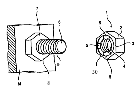
FIGS . 1 to 6 i1 lustrate the lock nut of the first embodiment
of the present invention. The lock nut 1 of the present
embodiment is constructed such that a seat surface 3 of a nut
body 2 such as a hexagonal nut, for example, having a
predetermined lead angle and a pitch clearance as a so-called
"female thread" is formed with a groove 30 at a circumferential
edge of a threaded hole 4 and three projections 5 in equal
spaced-apart relation in the groove 30. The projections 5 are
of the same material as the nut body 2.
A wide variety of materials can be used in making the
lock nut 1 according to its usage purpose and size . For example,
a metallic lock nut 1 is made from materials such as steel,
stainlesssteel,copper,and brass. Further,asynthetic-resin
lock nut 1 is made from materials such as polyvinyl chloride,
9
CA 02537081 2006-02-07
polycarbonate resin, polyacetal resin, ABS resin, and urea
resin.
The projection 5 has a tapered mountain-shaped form.
However, an outer side face 31 on the opposite side of the threaded
hole 4 is, as shown in FIGS. 2 to 4, directed toward a center
of the nut body 2 f rom the border between the seat surf ace 3
and the groove 30 of the nut body 2. Also, an inner side face
32 on the side of the threaded hole 4 is so made that its extension
arrives at about a midpoint between a root and a crest of the
thread groove of the nut 2.
As the lock nut 1 is fastened against the bolt 6 already
fastened which has been inserted into a fastened member M and
fastened by the fastening nut 7, the projections 5 formed on
the lock nut 1 are crushedbetweena seat surface 8 of the fastening
nut 7 and the groove 30 formed in the nut body 2 . In this regard,
as described above, the inner side face 32 of the projection
is so made as to be an extension of an inner face of the threaded
hole 4 of the nut body 2, and has a large contact area with
the threaded part 9 of the bolt 6 . Therefore, part of the crushed
proj ection 5 is fastened in such a way that it is applied around
the threaded part 9 of the bolt 6 . In this way, the proj ections
5 can apply a certain influence against a frictional force of
the threaded part 9 of the bolt 6 and the threaded hole 4 of
the lock nut 1.
In this regard, if each of these projections 5 is too
small, it is not to be applied around the threaded part 9 of
the bolt 6 when it is fastened against the bolt 6 and may not
CA 02537081 2006-02-07
act as a looseness-preventive member. To the contrary, if it
is too large, as described in regard to the lock nut of the
prior art, it may produce a large clearance between itself and
the inside fastening nut 7 and may not perform a function of
the double nut.
Therefore, according to the lock nut 1 of the present
embodiment, a height of the projection 5 is set to be about
300 of the length of the nut body 2 in the direction of the
central axis to make the proj ection 5 large enough so that the
projection 5 is applied around the threaded part 9 of the bolt
6 when it: is fastened against the bolt 6 and may act as a
looseness-preventive member. Also, in order to preventitfrom
producing a large clearance between itself and the inside
fastening nut 7 and to allow it to perform a function of the
double nut, a groove 30 is formed at the circumferential edge
of the threaded hole 4 of the seat surface 3 of the nut body
2 and projections 5 are formed in the groove 30. With this
construction, even when the projection 5 is crushed, it enters
the groove 30 so that it may not enter the space between the
seat surface 8 of the fastening nut 7 and the seat surface 3
of the nut body 2. Namely, a depth of the groove 30 is set
so that the crushed three proj ections 5 may not enter the space
between the seat surface 8 of the fastening nut 7 and the seat
surface 3 of the nut.
According to the present embodiment, three projections
are provided. However, the number of projections 5 may be
properly determined in response to a size or a shape of the
11
CA 02537081 2006-02-07
nut body 2. For example, in the case of a large nut body 2,
it is possible to provide four or five projections 5. In turn,
in the case of a small nut body 2, it is preferable that two
projections 5 may be provided. However, after these
projections 5 are crushed by twice fastening operations, they
are fastened in such a way that part of the crushed projection
may be applied around the threaded part 9 of the bolt 6 so
as to apply an influence against a frictional force of the
threaded part 9 of the bolt 6 , the threaded hole 4 of the lock
nut 1 and the threaded hole 10 of the fastening nut 7. It is
preferable that these projections 5 are arranged in a point
symmetrical state around a central point of a central axis of
the nut body 2 and the fastening nut 7 or in an equal-spaced
apart relation along the circumference of the thread groove.
FIGS. 5 (a) , 5 (b) , and 5 (c) show a state in which the lock
nut 1 of the present invention is fastened against the bolt
6. First, the usual fastening nut 7 is fastened against the
bolt 6 inserted into a part to be f fixed to a fastened member
M of a machine device or an iron frame of a building or the
like . Then, the lock nut 1 of the present invention is fastened
against the bolt 6 such that the projections 5 are faced against
the seat surface 8 of the fastening nut 7 (See FIG. 5 (a) ) . The
nut is fastened until the extremity of each projection 5 of
the lock nut 1 is contacted to the seat surface 8 of the fastening
nut 7 (See FIG. 5 (b) ) . In addition, as the lock nut 1 is further
fastened, the projections 5 are crushed by the fastening force
and the lock nut 1 can be approached to the fastening nut 7
12
CA 02537081 2006-02-07
(See FIG. 5(c)).
At this time, as shown in FIG. 6, the crushed projections
enter the groove 30 formed in the seat surface 3 of the nut
body 2 and they do not enter the space between the seat surf ace
3 of the nut body 2 and the seat surface 8 of the fastening
nut 7, which enables the seat surface 3 of the nut body 2 to
be contacted to the seat surface 8 of the fastening nut 7,
considerablyincreasing aforcefastening between thefastening
nut 7 and the lock nut 1. Further, since a part of the crushed
projections 5 is applied around the threaded part 9 of the bolt
6 under the crushed state, the crushed portions of the
projections 5 contribute to improvement of a frictional force
and an effect of looseness-prevention.
In the aforesaid preferred embodiment of the present
invention, the arrangement in which the proj ections 5 are formed
only at one seat surface 3 of the nut 1 has been described.
However, these projections 5 may be formed at both the seat
surfaces 3 of the nut body 2. If both the seat surfaces 3 of
the nut body 2 are formed with the projections 5, it is not
necessary to confirm a front surface or a rear surface of the
nut body 2 when it is fastened against the bolt 6 and so it
is possible to improve a fixing workability.
(Second Embodiment)
FIG. 7 is an enlarged side elevational view in section
of the lock nut according to a second embodiment of the present
invention. The lock nut 1 of the present embodiment differs
from the previously described lock nut 1 according to the first
13
CA 02537081 2006-02-07
embodiment in that each extremity of the projections 5 is formed
with a claw 11 directed toward a center of the nut body 2.
According to the lock nut 1 of the present embodiment,
when the lock nut 1 is fastened against the bolt 6 in the same
manner as that of the aforesaid first preferred embodiment,
the projections 5 are crushed by the seat surface 8 of the
fastening nut 7 and enter the groove 30, and part of each crushed
proj ection 5 is applied around the threaded part of the bolt
6 . When the proj ections 5 are provided with claws 11, the claws
11 are easily crushed by the seat surface 8 of the fastening
nut 7 and positively applied around the threaded part 9 of the
bolt 6. The claw 11 formed at the extremity of each of the
projections 5 has a function to contribute to improve a
frictional force of fastening between the threaded hole 4 of
the nut body 2 and the threaded part 9 of the bolt 6 and to
improve an effect of looseness-prevention.
(Third Embodiment)
FIG. 8 shows a lock nut according to a third embodiment
of the present invention. The lock nut 1 of the present
embodiment differs from the lock nut 1 of the second embodiment
described above in that the projection 5 is formed with a screw
head 12 threadably engaged with the threaded part 9 of the bolt
6.
According to the lock nut 1 of the present embodiment,
the projection 5 is formed with the screw head 12 threadably
engaged with the threaded part 9 of the bolt 6. Therefore,
forming of the screw head 12 at each of the proj ections 5 enables
14
CA 02537081 2006-02-07
the projection 5 to be easily crushed and further causes part
of the proj ection 5 to be easily applied around the threaded
part 9 of the bolt 6. As a result, the projection 5 formed
with the screw head 12 provides a positive looseness-preventive
action against the lock nut 1.
Further, the proj ection 5 of the lock nut 1 of the first
embodiment described above may be formed with a screw head 12
threadably engaged with the threaded part 9 of the bolt 6.
(Fourth Embodiment)
FIG. 9 shows a lock nut according to a fourth embodiment
of the present invention. The lock nut 1 of the present
embodiment differs from the lock nut 1 of the first embodiment
in that the extremity of the proj ection 5 is f fixed with a fastening
nut 7 in advance.
The lock nut 1 of the present embodiment is constructed
such that the fastening nut 7 is connected to the extremity
of the projection 5 by spot welding or by using a connecting
member 40 such as an adhesive agent. In this regard, the lock
nut 1 is connected to the fastening nut 7, in advance, by spot
welding or' by using the connecting member 40 such as the adhesive
agent in the vicinity of the threaded holes 4, 10 of the seat
surfaces 3, 8 of the two nuts 1, 7.
Further, concerning this lock nut 1, in order to fasten,
concurrently, the two nuts 1,7 connected in series to a bolt
6 inserted into a fastened member M such as various machine
devices or iron frames of a building or the like, the lock nut
1 and the fastening nut 7 are connected so that the nuts 1,
CA 02537081 2006-02-07
7 can be fastened against the bolt 6 even in a state where
proj ectic>ns 5 are formed according to the lead angles and pitch
clearances of the threaded holes 4, 10 of the nuts 1, 7 . Namely,
a height of the projections 5 is set so that the lead angle
and pitch. clearance of the threaded hole 4 of the lock nut 1
(nut body 2 ) coincide with the lead angle and pitch clearance
of the threaded hole 10 of the fastening nut 7 even when the
lock nut 1 is connected to the fastening nut 7.
The lock nut 1 having the fastening nut 7 connected thereto
is operated such that two nuts 1, 7 can be fastened concurrently
through one fastening operation by fastening it against the
bolt 6. Then, further fastening of only the outside lock nut
1 causes the welded portion or adhesive agent between the
projections 5 and the seat surface 8 of the fastening nut 7
to be broken and only the lock nut 1 can be fastened more. At
this time, the separated lock nut 1 is set such that each of
the proj ections 5 is crushed and can be fastened against the
seat surface 8 of the inside fastening nut 7. This projection
may also be fastened against the threaded part 9 of the bolt
6 so as to contribute to improvement of a frictional force of
fastening between the threaded holes 4, 10 of the nuts 1, 7
and the threaded part 9 of the bolt 6 and improve an effect
of looseness-prevention, and further the fastening action can
be carried out fast.
The lock nut 1 of the second and third embodiments described
above is also constructed such that the fastening nut 7 is
connected to the extremity of the projection 5 in advance.
16
CA 02537081 2006-02-07
(Modification)
In the aforesaid embodiments of the lock nut 1 of the
present invention, a shape and a thickness of the hexagonal
nuts 1, 7 arranged side by side have been described in reference
to the hexagonal nut of the same size and same shape. However,
it is satisfactory if a lock nut can be fastened against the
fastening nut 7 as a double nut and have a looseness-preventive
action, so that the shape of the nuts 1, 7 is not limited to
hexagon. For example, it is apparent that a thin lock nut 1
may also produce an effect of looseness-prevention and various
kinds of combination can be applied.
In each of the aforesaid preferred embodiments, the lock
nut 1 in which a hexagonal nut is formed with the projections
has been described. However, if the lock nut 1 is one in
which the nut is fastened against the fastening nut 7 to act
as the double nut, it is not limited to a hexagonal nut. It
is of course apparent that this lock nut 1 may be selected from
any of a rectangular nut, an octagonal nut, and other shapes.
Further, the description has been given as to the double
nut which is operated such that two nuts are fastened against
a bolt to fix various kinds of machine devices or iron frames
of a building or the like . However, the lock nut of the present
invention may be fastened against the bolt through a washer.
INDUSTRIAL APPLICABILITY
The lock nut of the present invention can be applied to
a double nut wherein two nuts are fastened against a bolt to
fixvarious kinds of machine devices or iron frames of a building
17
<IMG