Note: Descriptions are shown in the official language in which they were submitted.
CA 02537728 2006-02-24
Fuel Cell Fluid Dissipater
TECHNICAL FIELD
The present invention relates generally to a fluid dissipater for a fuel cell
generator.
BACKGROUND OF THE INVENTION
Fuel cells produce electricity from an electrochemical reaction between a
hydrogen-
containing fuel and oxygen. Fuel cell exhaust comprises oxidant and water and
some waste
heat, provided that pure hydrogen is used.
One type of fuel cell is a proton-exchange-membrane (PEM) fuel cell. PEM fuel
cells are
typically combined into fuel cell stacks to provide a greater voltage than can
be generated by a
single fuel cell. Fuel cell stacks are typically provided with manifolds that
distribute fluid to and
collect fluid from all of the constituent fuel cells. The manifolds are
provided with ports for
coupling to external fluid supply circuits, external fluid exhaust circuits
and external fluid
circulating circuits.
The fuel used by a PEM fuel cell is typically a gaseous fuel, and the gaseous
fuel is
typically hydrogen, but may be another hydrogen-containing fuel, such as
reformate. In a typical
PEM fuel cell, a chamber of hydrogen gas is separated from a chamber of
oxidant gas by a
proton-conductive membrane that is impermeable to oxidant gases. The membrane
is typically
formed of NAFION~ polymer manufactured by DuPont or some similar ion-
conductive polymer.
NAFION polymer is highly selectively permeable to water when exposed to gases.
In order for the fuel cell membrane to function properly, the membrane must be
hydrated; in typical PEM fuel cells, water vapor is continuously added to the
fuel supply stream
and to the oxidant supply stream in order to keep the fuel cell membranes
hydrated. Fuel cells
release more water into an exhaust stream than added to the fuel supply
stream, as hydrogen
atoms and oxygen atoms combine to produce water in the electrochemical
reaction of the fuel
cell. As water permeates very readily through the membrane separating the fuel
and the
oxidant, sufficient water can return from the oxidant side of the membrane to
the fuel side by
simple permeation as long as the high water concentration on the oxidant side
is maintained.
V 80080US\226902\I 1
CA 02537728 2006-02-24
Fuel cells often operate using air as the oxidant, relying upon the
approximately 20%
oxygen in ambient air. The use of air as an oxygen source requires a flow rate
of about air five
times that required for oxygen. When ambient air is used as an oxygen source,
this high flow
rate dries out the membrane by diluting the water vapor concentration on the
oxidant exhaust
S side of the membrane. If water can be recovered from the oxidant exhaust,
the need for a
separate water supply to keep the membrane hydrated for proper permeation of
hydrogen can
theoretically be eliminated.
Numerous system and methods for recirculating water vapour from exhaust gas
streams
to supply gas streams have been described. US patent application 2002/0155328
to Smith
describes a method and apparatus that recovers and recycles water from a fuel
ceU exhaust
and returns the water to the supply gases for the fuel cells. Particularly,
water vapor is
transferred from the exhaust gases to one or more supply gases by passing hot
humidified
exhaust gas over water permeable tubes, such that a supply gas flowing through
the tubes is
humidified by water permeating through the tubes and heated by heat conducted
through the
tubes from the exhaust gas. Commonly assigned US patent Pat. No. 6,864,005 to
Mossman
discloses and claims a membrane exchange humidifier, particularly for use in
humidifying
reactant streams for solid polymer electrolyte fuel cell systems.
A drawback of the described products is that the water available from the
oxidant
exhaust gas exceeds the water required for humidification of the fuel and
oxidant supply gas
streams, leaving excess water that needs to be disposed of. A further drawback
is that excess
water accumulates within the fuel cell gas supply channels after fuel cell
operation is shut down,
creating a surge of excess water when the fuel cell operation is re-started.
Existing solutions to dispose of excess water include storing such water in
tanks for
periodic discharge, and using an evaporator. Commonly assigned US patents
6,861,167,
6,960,401, and 6,979,504 disclose a fuel cell system wherein excess liquid
water is provided to
an evaporator, and the evaporator function is enhanced by air blown on the
evaporator by the
fuel cell system's cooling fan.
Another aspect of PEM fuel cell operation involves purging the fuel path
through the fuel
cells to return the electrochemical reaction to full capacity. The purged fuel
is typically vented
from the fuel exhaust stream to the environment; however, due to the danger of
creating a
flammable mixture of fuel and air in the presence of a potential source of
ignition, the purged
V80080US~22690211 2
CA 02537728 2006-02-24
fuel is diluted to below the lower flammability limit of the fuel before being
exposed to a potential
source of ignition, such as may be present in the environment. Known purging
solutions involve
dedicated components such as a purge fan and motor, additional piping etc.,
which add bulk
and complexity to the system.
Water disposal and fuel purging equipment are collectively known as "balance
of plant"
components of a fuel cell system. Such components add cost, bulk, weight, and
complexity to a
fuel cell system; also, some components require power, and thus constitute a
parasitic load on
the power generation capabilities of the fuel cell system. Reducing weight and
bulk are
particularly important concerns when engineering fuel cell systems for use in
applications were
available space is at a premium.
SUMMARY OF THE INVENTION
An object of the invention is to provide a fuel cell generator that solves at
least some of
the problems in the prior art. A particular objective is to provide a fuel
cell generator that
dissipates excess product water as well as unreacted fuel and air in a simple,
cost-effective and
space efficient manner.
According to one aspect of the invention, there is provided a fuel cell
generator
comprising a fuel cell and a fluid dissipater for dissipating fluids present
in the generator. The
fluid dissipater comprises a gas permeable and water absorbing evaporative
media, and a fluid
intake assembly fluidly coupled to the evaporative media and to the fuel cell
such that water and
gaseous unreacted fuel discharged by the fuel cell are directed to the
evaporative media for
dissipation out of the fuel cell generator. By combining fuel purge and water
disposal functions
of the fuel cell generator into a single apparatus, size, weight and
complexity of balance of plant
components in the generator can be reduced, thereby providing a cost-effective
fuel cell
generator that can be installed in confined spaces.
The fluid intake assembly can comprise one or more of the following
components:
~ a water trough fluidly coupled to the fuel cell such that water discharged
by the fuel
cell is directed to the trough; in such case, the evaporative media is located
in
sufficient proximity to the trough to wick water in the trough into the media;
V80080US\226902\1
CA 02537728 2006-02-24
~ a gas conduit having an inlet end fluidly coupled to the fuel cell and an
outlet end
fluidly coupled to the evaporative media, such that the fuel discharged from
the fuel
cell is directed into the media;
~ a fluid separator having a chamber fluidly coupled to a fluid exhaust stream
from the
fuel cell, a water outlet for directing water that has settled in the chamber
into the
trough, and a gas outlet for directing fuel from the exhaust stream to the gas
conduit;
and/or
~ a fluid separation chamber fluidly coupled to the media, a gas inlet fluidly
coupled to
the gas conduit, a water inlet fluidly coupled to the fluid separator water
outlet, and a
water outlet located below the gas and water inlets and fluidly coupled to the
trough.
Further, a lower portion of the media can be positioned to contact water in
the trough,
and an upper portion of the media can be positioned to receive fuel from the
gas conduit. This
arrangement is particularly useful to reduce splashing or spitting that can
occur when water and
gases are discharged together onto the media. Also, the dissipater can
comprise multiple
troughs and multiple evaporative media each located in sufficient proximity to
an associated
trough to wick water in the trough into the media. Using multiple such troughs
and media
increases the size and dissipation capacity of the dissipater.
The fuel cell generator can further comprise a fan facing the evaporative
media and
configured to direct an air stream through the media to dissipate water and
fuel in the media out
of the fuel cell generator. The oxidant intake of the fuel cell can be in
fluid communication with
the air stream, such that the air stream provides oxidant to the fuel cell as
well as dissipates
fluids contained in the dissipater. The fuel cell generator can also have a
radiator thermally
coupled to the fuel cell and that has heat exchanger elements located between
the fan and the
media such that heat is discharged from the heat exchanger elements into the
air stream.
BRIEF DESCRIPTION OF THE DRAWINGS
Fig. 1 is a schematic side view of a fuel cell generator including a fuel cell
fluid dissipater
according to one embodiment of the invention.
Fig. 2 is a schematic side view of a fluid separator of the dissipater shown
in Fig. 1.
vsoosous~269o2u
CA 02537728 2006-02-24
Fig. 3 is a sectioned edge view of a dissipation media assembly of the
dissipater shown in
Fig. 1.
Fig. 4 is a sectioned side view of the dissipation media assembly shown in
Fig. 3.
Fig. 5 is another sectioned side view of the dissipation media assembly shown
in Fig. 3.
Fig. 6 is a side view of a cooling system radiator of the fuel cell generator
shown in Fig. 1.
Fig. 7 is a side view of the dissipater shown in Fig. 1.
Figs. 8a and 8b are sectioned edge views of a dissipation media assembly of
the fuel cell
generator according to two other embodiments of the invention.
DETAILED DESCRIPTION OF EMBODIMENTS OF THE INVENTION
Referring to Fig. 1 and according to a preferred embodiment of the invention,
a fuel cell
generator 5 includes a fuel cell stack 50, a fuel cell generator enclosure 54,
an enclosure air
inlet 58, enclosure air outlet 55; and within the enclosure 54 an air inlet
particulate filter 59, a
fuel cell excess fluids outlet 11, an excess fluids conduit 7, and a fluid
dissipater 10.
The fuel cell stack 50 may be any suitable PEM fuel cell stack as known in the
art, such
as Ballard Power System's Mark 9 series fuel cell stack. Such fuel cell stacks
electrochemically
react oxidant (typically from air) and gaseous hydrogen fuel to produce
electricity, heat and
product water; unreacted fuel, unreacted air, and excess water are typically
discharged from the
fuel cell.
The fluid dissipater 10 includes a fluid separator 12, an excess water conduit
8, an
excess gas conduit 9, a dissipation media assembly 20, a cooling system fan
70, and a cooling
system radiator 80. The fluid dissipater 10 operates to quickly and completely
dissipate fluids
discharged by the fuel cell stack 50, namely excess water and unreacted
gaseous fuel cell fuel
and air from the fuel cell generator 5. These fluids are directed from the
fuel cell stack 50 to
dissipation media in the fluid dissipater 10. The dissipation media are
exposed to an air stream
blown by the cooling system fan 70 through the cooling system radiator 80 and
through the
dissipation media assembly 20, which serves to quickly dissipate the fluids
into the air stream
and discharge the fluids from the fuel cell generator 5 to the environment.
The fluid dissipater 10
V80080US\226902\1
CA 02537728 2006-02-24
operates to completely remove excess fluids to the environment. The fluid
dissipater 10 also
operates to safely dilute unreacted fuel to the environment.
The enclosure air inlet 58 is coupled to the air inlet particulate filter 59.
The filter 59
prevents the incursion of air-borne particulate matters into the interior of
the fuel cell generator
enclosure 54. During operation of the fuel cell generator 5, the cooling
system fan 70 operates,
drawing air through the enclosure air inlet 58 into the interior of the fuel
cell generator enclosure
54, and then through the dissipation media assembly 20. Inclusion of the
particulate air filter 59
ensures that the air stream that enters the fluid dissipater 10 does not
contain particulate matter.
A suitable air particulate filter is provided by Web Products Inc., under the
name Three Phase
Electrostatic Filter, however, other particulate filters having similar
properties can be substituted
within the scope of this invention.
Air leaves the dissipation media assembly 20 into the interior of the
enclosure 54. Close
spacing of the dissipation media assembly 20 to the enclosure air outlet 55
and perimeter
sealing of the air path from the dissipation media assembly 20 to the
enclosure air outlet 55
allows the entire air stream to immediately pass through the enclosure air
outlet 55 to the
environment.
During operation of the fuel cell generator 5, excess fuel cell fluids flow
through the fuel
cell excess fluids outlet 11 and the excess fluids conduit 7 due partially to
the pressure they
receive from the operation of the fuel cell generator 5 and partially through
the force of gravity.
The excess fluids may at times consist of one or more different fluids
depending on the
operational state of the coupled fuel cell generator 5. The excess fluids may
include liquid water,
water vapour, unreacted fuel cell fuel and air; the fuel cell fuel typically
being gaseous hydrogen.
Referring to Figure 2, the fluid separator 12 includes a fluid inlet 13, a
water outlet 14
and a gas outlet 15. In this embodiment of the invention, the excess fuel cell
fluids stream
passes from the fuel cell excess fluids outlet 11 through the excess fluids
conduit 7 and the fluid
inlet 13 into the fluid separator 12. Water in the fluid stream settles by
gravity to the bottom
portion of the fluid separator 12 and exits the fluid separator 12 by way of
the water outlet 14.
The water may include some entrained gases. The gases in the fuel cell fluids
stream rise to the
top portion of the fluid separator 12 and exit the fluid separator 12 by way
of the gas outlet 15.
The gases may include air, unreacted gaseous fuel cell fuel and water vapour.
The gases may
include some entrained liquid water.
V 80080US\226902U
CA 02537728 2006-02-24
Referring to Figures 3-5, the dissipation media assembly 20 includes an air
inlet 28, an
air outlet 29, a water inlet port 22 and a gas inlet port 16. The dissipation
media assembly 20
also includes a frame 27, a gas inlet 17, a gas distribution chamber 18, a gas
distribution outlet
19, the water inlet port 22, a water inlet 23, a water distribution chamber
25, a water distribution
chamber bleed hole 26, a V-notch weir 45, a first water conduit 31, a second
water conduit 32, a
third water conduit 33, a first overflow outlet 41, a second overflow outlet
42, an overflow
conduit 43, a first water trough 36, a second water trough 37, a third water
trough 38, a first
dissipater section 61, a second dissipater section 62, and a third dissipater
section 63, a first
dissipation medium 51, a second dissipation medium 52, and a third dissipation
medium 53.
These components excluding the media 51 52, 53 are considered part of a fluid
intake assembly
that serves to direct fluids from the fuel cell stack 50 to the media 51, 52,
53.
The gas stream is directed from the gas outlet 15 by way of the excess gas
conduit 9 to
the gas inlet port 16 and a gas inlet 17 into a gas distribution chamber 18 of
the dissipation
media assembly 20.
The gas distribution chamber 18 is vertically continuous to the water
distribution
chamber 25, such that liquid water entrained in the gas stream may precipitate
downward from
the gas distribution chamber 18 into the water distribution chamber 25.
From the gas distribution chamber 18, the gas stream flows through the gas
distribution
outlet 19 into the first dissipater section 61 where the gas stream flows into
the first dissipation
medium 51 and the adjacent air space, where the gases dissipate further
according to the
properties of the constituent gases.
In this embodiment, the gas distribution outlet 19 comprises a plurality of
orifices;
however, a single orifice could be used without detracting from the invention.
The air stream flowing through the dissipation media assembly 20 (via air
inlet 28 and air
outlet 29) increases the speed of gas dissipation through the enclosure air
outlet 55 to the
environment.
The water stream is conveyed from the water outlet 14 by way of the excess
water
conduit 8 to the water inlet port 22 and the water inlet 23 into a water
distribution chamber 25 of
the dissipation media assembly 20.
Gas entrained in the water stream may rise into the gas distribution chamber
18.
V80080US\226902\1 7
CA 02537728 2006-02-24
The water distribution chamber 25 is vertically elongate and has the bleed
hole 26 near
the bottom of the chamber and the V-notch weir 45 part way up one side of the
chamber. The V-
notch weir 45 includes a first V-notch port 46, a second V-notch port 47 and a
third V-notch port
48 all having a bottom edge at the same height within the water distribution
chamber 25 and in
which the third V-notch port 48 is taller than the first and second V-notch
ports 46, 47. When the
water in the chamber 25 reaches the bottom level of the V-notch weir 45, the
water flows
simultaneously into the bottom of the V-notch ports 46, 47, 48 and
therethrough into the first
water conduit 31, the second water conduit 32, and the third water conduit 33
respectively.
When the water in the water distribution chamber 25 rises above the bottom
level of the V-notch
weir 45, the flow of water through V-notch ports 46, 47, 48 increases
according to the width of
the V-notches at that level. When the water in the chamber 25 rises above the
top level of the
first and second V-notch ports 46, 47, the flow of water through V-notches 46,
47 cannot
increase further, and the flow of water through the third V-notch port 48
increases according to
the width of the V-notch at that level.
1 S The bleed hole 26 is sized to allow a slow bleeding of water out of the
water distribution
chamber 25 into the third water conduit 33. The inclusion of the bleed hole 26
allows the water
distribution chamber 25 to drain when water is not entering the fluid
dissipater 10, for example
when the fuel cell generator 5 shuts down.
The water stream entering the dissipation media assembly 20 varies during
operation of
the fuel cell generator 5, resulting in surges of water entering the water
distribution chamber 25.
Emptying of the water distribution chamber 25 during no-flow periods provides
a water volume
buffer for when a surge of water enters the fluid dissipater 10, such as when
the fuel cell
generator 5 starts up, or when a fuel cell purge valve (not shown) opens.
In this arrangement, a non-excessive steady stream of water is distributed
evenly
through the three V-notch ports 46, 47, 48 into the three respective water
conduits 31, 32, 33;
while a surge in the water stream causes some or all of the additional water
to enter the third V
notch port 48 and therethrough into the third water conduit 33; and at all
times when water is
present in chamber 25, the water bleeds through bleed hole 26 into the third
water conduit 33.
The rate of water flow through the bleed hole 26 is less than the flow of
water through the V
notch weir 45 whenever water is flowing through the V-notch weir.
V80080US\226902\1
CA 02537728 2006-02-24
The provision of a water distribution chamber 25 to contain a volume of water,
a bleed
hole 26 to empty water from the bottom of the chamber 25 into the third water
conduit 33, and a
third V-notch port 48 that is larger than a first and a second V-notch port
46, 47 allows the fluid
dissipater 10 to distribute the water stream to the water conduits 31, 32, 33
preferentially to the
third water conduit 33.
Alternatively, the bottom of one or two of the V-notch ports 46, 47, 48 can be
at different
levels, and the V-notch ports can be of different sizes or shapes. The V-notch
weir 45 can
alternatively contain a different number of V-notch ports.
First, second and third water conduits 31, 32, 33 are largely vertically
elongate such that
water flows downward through them under the force of gravity. The first water
conduit 31 is
coupled to the first water trough inlet 36a and the first water trough 36,
such that the water
stream in the first water conduit 31 flows downward into the first water
trough inlet 36a and the
first water trough 36. The second water conduit 32 is coupled to the second
water trough inlet
37a and the second water trough 37, such that the water stream in the second
water conduit 32
flows downward into the second water trough inlet 37a and the second water
trough 37. The
third water conduit 33 is coupled to the third water trough inlet 38a and the
third water trough
38, such that the water stream in the third water conduit 31 flows downward
into the third water
trough inlet 38a and the third water trough 38.
The first water trough 36 and the second water trough 37 are designed to have
a
minimal vertical dimension to minimize obstruction of the air stream. In this
embodiment, the
first water trough 36 and the second water trough 37 are each less than
fifteen (15) millimeters
in height.
First, second and third water troughs 36, 37, 38 are largely horizontally
elongate, such
that water in the troughs spreads evenly along the tray. The third water
trough 38 is larger in
liquid capacity than each of the first and second water troughs 36, 37; the
larger liquid capacity
corresponding to the larger water flow that may traverse the third water
conduit 33.
The dissipation media assembly 20 is largely divided into three largely
horizontal
dissipater sections, the first dissipater section 61 located above the second
dissipater section
62, and the second dissipater section 62 located above the third dissipater
section 63. The
bottom edge of the first dissipater section 61 is defined by the bottom of the
first water trough
36. The bottom edge of the second dissipater section 62 is defined by the
bottom of the second
V80080US\226902\1
CA 02537728 2006-02-24
water trough 37. The bottom edge of the third dissipater section 63 is defined
by the bottom of
the third water trough 38.
The first dissipation medium 51 is located within the first dissipater section
61 and the
bottom edge of the first dissipation medium 51 is located within the first
water trough 36. The
second dissipation medium 52 is located within the second dissipater section
62 and the bottom
edge of the second dissipation medium 52 is located within the second water
trough 37. The
third dissipation medium 53 is located within the third dissipater section 63
and the bottom edge
of the third dissipation medium 53 is located within the third water trough
38. Dissipation media
are welt known and have been described as contact bodies, flocking, evaporator
pads, and
evaporator paper. A suitable dissipation medium for this invention is a
cellulose product
provided by the Columbus industries Inc. under the description WICK MDNB;
however, other
dissipation media that have similar gas permeable and water absorbing and
evaporative
properties can be substituted within the scope of this invention.
The positioning of a dissipation medium such that the bottom edge of the
medium is
within a water trough causes water in the water trough to wick upwards
naturally through the
dissipation medium. The dissipation media 51, 52, 53 are each limited in
height to within the
range of height to which water can wick naturally for the dissipation media.
In operation, water in
the first water trough 36 is wicked into the first dissipation medium 51,
water in the second water
trough 37 is wicked into the second dissipation medium 52, and water in the
third water trough
38 is wicked into the third dissipation medium 53.
Water in the dissipation media 51, 52, 53 evaporates naturally according to
ambient
temperature and humidity conditions, and additionally according to air flow
rate.
In this embodiment, the water conduits 31, 32, 33 are directly coupled to
their respective
troughs 36, 37, 38 without any intervening barrier, orifice or restriction.
Alternatively, one or
more of the water conduits may include a barrier, orifice or restriction (not
shown) to reduce the
incidence of splashing or to reduce water flow; for example, an orifice can be
located in the side
of the water conduits 31, 32, 33 with the bottom level of the orifice located
between the top and
bottom levels of the water troughs 36, 37, 38 respectively.
Optionally, the water conduits 31, 32, 33 can contain respective orifices (not
shown) that
allow water to pass from the conduit 31, 32, 33 to the side edge of the
respective dissipation
medium 51, 52, 53, thereby wicking into the medium 51, 52, 53 respectively.
Alternatively, water
V80080US~226902U
CA 02537728 2006-02-24
passes from the second water conduit 32 through an orifice (not shown) and
comes into contact
with a side edge of the first dissipation medium 51 and thereby wicks into the
medium. Likewise,
water passes from the third water conduit 33 through an orifice (not shown)
and come into
contact with a side edge of the first dissipation medium 51 and/or the second
dissipation
medium 52 and thereby wicks into the medium.
The first water trough 36 has the first overflow outlet 41. The first overflow
outlet 41 may
be a passage or passages through a side of the first water trough 36, or the
outlet 41 may be a
portion or portions of a side of the trough 36 that is lower than the
remainder of the trough's
sides. During operation, the water stream may enter the first water trough 36
at a flow that is
greater than the evaporative capacity of the first dissipation medium 51,
resulting in an
increasing water level within the first water trough 36. When the water level
in the first water
trough 36 increases to the level of the first overflow outlet 41, a first
overflow water stream
traverses the first overflow outlet 41 and enters the overflow conduit 43. The
second water
trough 37 has a similar overflow outlet 42 and a second overtlow water stream.
The overflow conduit 43 is largely vertically elongate such that the overflow
water
streams flow downward through the overflow conduit 43 under the force of
gravity. The overflow
conduit 43 conveys the first overflow water stream and the second overflow
water stream to the
third water trough 38.
In an alternate embodiment, the water troughs 36, 37, 38 additionally each
have an
overtlow outlet (not shown) that conveys overflow water to the third water
conduit 33. In another
alternate embodiment, the water troughs 36, 37, 38 have an overflow outlet
that conveys
overflow water to the third water conduit 33 instead of the first and second
overflow outlets 41,
42. In these embodiments, the inclusion of overflow outlets at both ends of
the first and second
water troughs 36, 37 prevents water from spilling out of the troughs in the
event that the fuel cell
generator 5 becomes tilted.
In this embodiment, the overflow conduit 43 is directly coupled to the first
water trough
36 without any intervening barrier, orifice or restriction. In an alternate
embodiment, the water
stream in the overflow conduit 43 traverses a fourth water trough water inlet
(not shown) into the
third water trough 38. The fourth water trough water inlet (not shown) may
consist of a barrier,
orifice or restriction that functions to reduce splashing or reduce water
flow. In this case, the
fourth water trough water inlet consists of an orifice in the side of the
overflow conduit 43, the
V80080US\226902\1 1 1
CA 02537728 2006-02-24
bottom of the orifice located above the bottom of the third water trough 38,
and below the top of
the third water trough 38.
Fuel cell power system startup is characterized by the flushing of accumulated
water
from the fuel cell stack 50 and associated components. Fuei cell power system
fuel purge may
be accompanied by the flushing of wafer from the fuel cell stack 50 and
associated components.
Flushing accumulated water from fuel cell stacks 50 like the Ballard Power
Systems Mark 9
series stack used in this invention are well known in the art and therefore
not described here.
Flushing of accumulated water can cause a large surge of water into the fluid
dissipater
10. The large surge of water may quickly fill the water distribution chamber
25 such that the
water level rises to cover all of the V-notch ports 46, 47, 48. The additional
water accumulates
within the water distribution chamber 25, raising the level of water within
the chamber 25. As the
water distribution chamber 25 is vertically continuous with the gas
distribution chamber 18, a
large surge of water entering the water distribution chamber 25 can raise the
water level within
the water distribution chamber 25 such that the water occupies the gas
distribution chamber 18.
The water's occupation of the gas distribution chamber 18 is temporary because
water is
continuously being reduced through water traverse of the bleed hole 26 and the
V-notch weir
45. During the water's occupation of the gas distribution chamber 18, whenever
the water rises
to cover even part of the gas distribution outlet 19, water traverses the gas
distribution outlet 19
into the first dissipater section 61; the water comes into contact with the
first dissipation medium
51 and is largely absorbed by the dissipation medium 51. The gas distribution
outlet 19 is
preferentially located to bring fluids into contact with the first dissipation
medium 51 near the top
edge of the medium such that water traversing the gas distribution outlet 19
contacts the
dissipation medium 51 distantly from the first water trough 36. In this way, a
large surge of water
from the fuel cell generator 5 that overfills the water distribution chamber
25 is conveyed to a
dissipation medium without overflowing from the dissipation media assembly 20.
Alternatively, water in the gas distribution chamber 18 can be routed to the
second
dissipater section 62 or the third dissipater section 63, or any combination
of dissipater sections
61, 62, 63 within the scope of the invention.
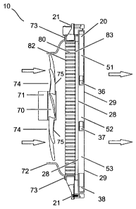
Referring to Figure 7, the cooling system fan 70 includes a cooling fan air
inlet 74 and
cooling fan air outlet 75 and a cooling fan motor 71. Much of the air stream
within the enclosure
54 is drawn by the cooling system fan 70 through the cooling fan air inlet 74
into the cooling
V80080US\226902\I I 2
CA 02537728 2006-02-24
system fan 70. The cooling system 70 fan blows the air sequentially through a
cooling fan air
outlet 75, the radiator air inlet 82, the radiator 80 and the radiator air
outlet 83, the dissipater air
inlet 28, the dissipation media 51, 52, 53, the dissipater air outlet 29, and
the enclosure air outlet
55 to the environment.
Referring to Figure 6, the radiator 80 includes a radiator air inlet 82, and a
radiator air
outlet 83. The radiator 80 is part of the fuel cell generator's cooling
system, and is arranged to
input heated water through a radiator water inlet 84 and output cooled water
through a radiator
water outlet 85. The radiator used here is a standard type of radiator that is
well known,
including a plurality of water conduits shaped to maximize water conduit
surface area between
the radiator water inlet 84 and the radiator water outlet 85. The conduit
surfaces serve to
transfer heat from the heated water within the water conduits to the air
surrounding the water
conduits. In this embodiment, the radiator is arranged in close proximity to
the cooling system
fan 70 such that air impelled by the cooling system fan 70 enters the radiator
air inlet 82, makes
contact with the radiator's plurality of water conduits and exits through the
radiator air outlet 83.
In this arrangement, heat from the radiator 80 is transferred to the air,
which in turn transfers
heat to the dissipation media 51, 52, 53 and the water in the dissipation
media, thereby
speeding evaporation of the water.
Referring to Figure 7, the radiator 80 has one or more fasteners 21 that
attach the
radiator 80 to the fluid dissipater frame 27; however, the radiator 80 could
be fastened in
another manner and to another fuel cell generator component within the scope
of the invention.
A cooling fan shroud 72 surrounding the cooling fan 70 and attached to the
radiator 70 by way
of fasteners 73 allows the entire air stream from the cooling fan air outlet
75 to traverse the
radiator 80.
A radiator-to-dissipater seal (not shown) attached to the periphery of the
radiator 80 and
the periphery of the dissipation media assembly 20 is provided to prevent the
incursion of air
into the interior of the fuel cell enclosure during operation. The prevention
of incursion of air into
the interior of the fuel cell enclosure during operation ensures that the air
stream flows directly
from the radiator to the dissipation media assembly 20. The radiator-to-
dissipater seal is made
of a high temperature tolerant adhesive film tape, provided by Shercon Inc.,
under the part
number PC21, but may be another adhesive film tape or another sealing material
without
detracting from the invention.
V80080US~226902\I 13
CA 02537728 2006-02-24
The air stream flowing through the dissipation media 51, 52, 53 speeds
evaporation of
wicked water in the media, and dissipation of the gas in the dissipation
medium 51.
A dissipater-to-enclosure seal (not shown) attached to the periphery of the
dissipation
media assembly 20 and the periphery of the enclosure air outlet 55 is provided
to prevent the
incursion of air into the interior of the fuel cell enclosure during
operation. The prevention of
incursion of air into the interior of the fuel cell enclosure during operation
ensures that the air
stream flows directly from the dissipation media assembly 20 to the enclosure
air outlet 55 and
the environment.
The dissipater-to-enclosure seal is made of a high temperature tolerant
adhesive film
tape, provided by Shercon Inc., under the part number PC21, but may be another
adhesive film
tape or another sealing material without detracting from the invention.
In an alternate embodiment of this invention, where a fuel cell generator 5
has a cooling
system in which the cooling fan is located downstream of the radiator, and the
cooling fan sucks
air through the radiator, the dissipation media assembly 20 is preferentially
located between the
radiator and the cooling fan, or between the cooling fan and the enclosure air
outlet 55.
In another alternate embodiment of this invention, the radiator 80 may be
deleted. In this
case, the cooling fan shroud 72 is attached directly to the dissipation media
assembly 20.
A particular advantage of the fluid dissipater 10 as described above is that
the fluid
dissipater 10 operates to dissipate fluid without the need for external power
or control.
Therefore, the fluid dissipater 10 does not impose a parasitic power loss to
the system 5, nor
requires the added expense and complexity of a controller.
The fluid dissipater 10 should be designed to accommodate variations in fuel
cell
generator 5 operation. For example, a controller (not shown) can vary the rate
of power
generation of the fuel cell stack 50 by changing the air flow rate to the fuel
cell stack 50. Such
change in air flow rate affects the fluid dissipation rate by the fluid
dissipater 10. Selection of the
fluid dissipater 10 components such as the type of dissipation media 51, 52,
53, and the size
and shape of water troughs 36, 37, 38 should therefore be made to ensure that
the fluid
dissipater 10 can handle the full range of excess fluids output by the fuel
cell generator 5.
According to other embodiments of the invention, a separate fluid separator 12
is not
used, and fluid separation takes place within the dissipation media assembly
20. In one such
V80080US~226902U 14
CA 02537728 2006-02-24
embodiment and referring to Fig. 8a, the excess fuel cell fluids stream from
the fuel cell excess
fluids outlet 11 traverses the excess fluids conduit 7 to the fluid inlet 13a
of the dissipation
media assembly 20 and into the gas distribution chamber 18. The gas
distribution chamber 18 is
vertically elongate and is above and continuous with the water distribution
chamber 25. In
operation, the excess fluids in the gas distribution chamber 18 separate
naturally with the liquids
falling under the force of gravity into the water distribution chamber 25, and
the gases occupying
the gas distribution chamber 18. The water may contain some entrained gases,
and the gases
may include some water vapour.
In another such embodiment, and referring to Fig. 8b, the excess fuel cell
fluids stream
from the fuel cell excess fluids outlet 11 traverses the excess fluids conduit
7 to the fluid inlet
13b of the dissipation media assembly 20 and into the water distribution
chamber 25. In
operation, the excess fluids in the water distribution chamber 25 separate
naturally with the
gases rising into the gas distribution chamber 18, and the liquids occupying
the water
distribution chamber 25. The water may contain some entrained gases, and the
gases may
include some water vapour.
In another such embodiment, the fluid inlet can be located between the
locations of fluid
inlet 13a and fluid inlet 13b, as long as the fluids are conveyed to either
the water distribution
chamber 25 or the gas distribution chamber 18, or otherwise distributed to the
two chambers 25,
18.
In an alternate embodiment, the fluid dissipater 10 incorporates a motor
actuated water
pump (not shown) and a return water conduit (not shown) provided to convey
water from the
third water trough 38 to the water distribution chamber 25_ The power to power
the motor of the
motor actuated water pump comes from the fuel cell generator 5. In this
embodiment the water
pump operates continuously whenever the fuel cell generator 5 is operating.
In a further alternate embodiment, the fluid dissipater 10 incorporates a high
water level
sensor (not shown) in the third water trough 38 provided to sense a high wafer
Level and
capable of sending a signal to a controller such as a fuel cell power system
controller (not
shown). The water pump of this embodiment is activated by a signal from the
controller,
whenever the high level wafer sensor is triggered.
In further alternate embodiments, the fluid dissipater 10 incorporates a motor
actuated
water pump (not shown) and a supply water conduit (not shown) provided to
convey water from
V80080US1226902\1 1$
CA 02537728 2006-02-24
one of the excess fluids outlet 11 and the water outlet 14 to one or more of
the water distribution
chamber 25, the gas distribution chamber 18, the first, second and third water
troughs 36, 37,
38, the first, second, and third water conduits 31, 32, 33, and the overflow
conduit 43.
It is to be understood that even though various embodiments and advantages of
the
present invention have been set forth in the foregoing description, the above
disclosure is
illustrative only, and changes may be made in detail, and yet remain within
the broad principles
of the invention. Therefore, the present invention is to be limited only by
the claims appended to
the patent.
vsoosous~69ozu 16