Note: Descriptions are shown in the official language in which they were submitted.
CA 02537775 2006-02-27
COFFEE FLAVOUR DISPENSER
FIELD OF THE INVENTION
The present invention relates to flavour dispensers used in beverage-making
equipment. More specifically, the invention relates to coffee flavour
dispensers for
dispensing a metered amount of flavouring liquid to a coffee beverage.
BACKGROUND OF THE INVENTION
Flavoured beverages are increasingly popular with consumers. Beverage
dispensing systems are commonly used to provide consumers with flavoured
beverages such as chocolate, coffee, tea, and the like.
io Numerous coffee dispensing systems provide flavoured coffee brewed from pre-
flavoured coffee beans or grinds stored in the system. Pre-flavoured coffee
beans
are whole coffee beans that have been coated with flavouring during roasting.
A
metered amount of the pre-flavoured coffee beans stored in the dispensing
system
is ground and used to brew the flavoured coffee. Pre-flavoured coffee grinds
are
grinds of coffee to which flavouring has been added.
Many pre-flavoured coffees are produced using synthetic chemical flavourings.
For
many consumers, the use of synthetic chemical flavourings is a point against
this
type of coffee dispensing system. Of course, pre-flavoured coffee infused with
natural flavourings may be used instead, offering rich aroma and better taste.
Unfortunately, such naturally-flavoured coffee is often more expensive and may
not be competitive in terms of cost.
As tastes differ around the world, there is a constant demand for consistency
in
quality. It can be quite difficult to obtain good pre-flavoured coffee grinds.
The finer
the grind, the more difficult it is to obtain good uniform mixing of the
flavouring.
Moreover, these systems that use pre-flavoured coffee have a high risk of
CA 02537775 2006-02-27
2
contamination with other coffee products in the grinders and/or feeding
equipment
between coffee-making processes.
As disclosed in US Patent Application No. 2005/0066819, one possible solution
to
the problem of contamination is the use of in-cup vending systems in which
stacked cups, each containing a portion of beverage-making ingredients, are
stored in the dispenser of the vending machine. One obvious drawback to this
system is the bulky size of the vending machine owing to the large volume of
the
stored stacked cups. Another solution to the contamination problem disclosed
in
US Patent Application No. 2005/0066819 is the use of stored beverage-making
to capsules. The drawback with this solution is the added bulk and cost of the
packaging of the individual capsules.
US Patent No. 6,730,348 discloses dispensing a flavoured syrup in a manually
positioned pre-packaged shake-mix-filled container for forming a flavoured
slurried
confection. This particular beverage dispensing system, designed for such
1s beverages as milkshakes and not suited for such beverages as coffee, does
not
provide efficient means for preventing contamination from beverage ingredients
between beverage-making processes.
SUMMARY OF THE INVENTION
In accordance with one aspect of the present invention, there is provided a
flavour
2o dispensing mechanism for a coffee dispensing machine, for dispensing at
least
one flavouring liquid to a coffee beverage. The flavour dispensing mechanism
includes at least one flavouring liquid source having an outlet for outputting
a flow
of a corresponding one of the at least one flavouring liquid. For each one of
the at
least one flavouring liquid source, the flavour dispensing mechanism includes
25 drawing means for controllably drawing a metered amount of the
corresponding
flavouring liquid from the at least one flavouring liquid source, a delivery
tube
having an input end connected to the drawing means for receiving the metered
CA 02537775 2006-02-27
3
amount of the corresponding flavouring liquid therefrom and an output end
opposite the input end for delivering the metered amount of the corresponding
flavouring liquid to the coffee beverage, and displacing means for displacing
the
metered amount of the corresponding flavouring liquid in the delivery tube,
the
displacing means being adapted to prevent dripping of the corresponding
flavouring liquid-Trom the output end of the delivery tube apart from
delivering the
metered amount thereof to the coffee beverage.
In an embodiment of the flavour dispensing mechanism, the drawing means
preferably include a flow-regulating device, connected between the flavouring
to liquid source and the delivery tube, for drawing the flavouring liquid from
the
flavouring liquid source to the delivery tube, and a controller, connected to
the
flow-regulating device, for actuating the flow-regulating device to deliver
the
metered amount of the flavouring liquid to the delivery tube. According to one
embodiment, the flow-regulating device may preferably include a pump.
According to another embodiment, the flow-regulating device may preferably
include a valve.
In accordance with another embodiment of the present invention, there is
provided
a coffee dispensing machine with a flavour dispensing mechanism for dispensing
at least one flavouring liquid to a coffee beverage. The flavour dispensing
mechanism includes at least one flavouring liquid source having an outlet for
outputting a flow of a corresponding one of the at least one flavouring
liquid. For
each one of the at least one flavouring liquid source, the flavour dispensing
mechanism includes drawing means for controllably drawing a metered amount of
the corresponding flavouring liquid from the at least one flavouring liquid
source, a
delivery tube having an input end connected to the drawing means for receiving
the metered amount of the corresponding flavouring liquid therefrom and an
output
end opposite the input end for delivering the metered amount of the
corresponding
flavouring liquid to the coffee beverage, and displacing means for displacing
the
metered amount of the corresponding flavouring liquid in the delivery tube,
the
CA 02537775 2006-02-27
4
displacing means being adapted to prevent dripping of the corresponding
flavouring liquid from the output end of the delivery tube apart from
delivering the
metered amount thereof to the coffee beverage.
In an embodiment of the present invention, the coffee dispensing machine may
include selection means for selecting the at least one flavouring liquid, the
selection means being in communication with the drawing means.
In accordance with another aspect of the invention, there is provided a method
for
incorporating, to a coffee dispensing machine, a flavour dispensing mechanism
for
dispensing at least one flavouring liquid to a coffee beverage. The method
io includes the steps of:
- providing at least one flavouring liquid source having an outlet for
outputting a flow of a corresponding one of the at least one flavouring
liquid;
- providing drawing means for controllably drawing a metered amount
of the flavouring liquid from the source of flavouring liquid;
- connecting an input end of a delivery tube to the drawing means for
receiving the metered amount of the corresponding flavouring liquid
therefrom, and providing an output end opposite the input end of the
delivery tube for delivering the metered amount of flavouring liquid to
a coffee beverage; and
- providing displacing means for displacing the metered amount of the
corresponding flavouring liquid in the delivery tube, the displacing
means being adapted to prevent dripping of the corresponding
flavouring liquid from the output end of the delivery tube apart from
delivering the metered amount thereof to the coffee beverage.
Preferably, the above method includes the step of providing selection means
for
selecting the at least one flavouring liquid, the selection means being in
communication with the drawing means.
CA 02537775 2006-02-27
Advantages of the present invention include a flavour dispensing mechanism for
a
coffee dispensing machine that offers an efficient, consistent, cost-effective
means
of producing a quaiity flavoured coffee.
5 The objects, advantages and other features of the present invention will
become
more apparent and be better understood upon reading of the following non-
restrictive description of the preferred embodiments of the invention, given
with
reference to the accompanying drawings. The accompanying drawings are given
purely for illustrative purposes and should not in any way be interpreted as
limiting
io the scope of the invention.
BRIEF DESCRIPTION OF THE DRAWINGS
Figure 1 is a perspective view of a coffee dispensing machine according to a
preferred embodiment of the invention.
Figure 2 is a perspective view of the interior of a coffee dispensing machine
showing a flavour dispensing mechanism incorporated into the door of the
coffee
dispensing machine, according to a preferred embodiment of the invention.
Figure 3 is a front view of a flavour dispensing mechanism incorporated into
the
door of the coffee dispensing machine, according to a preferred embodiment of
the invention.
2o Figure 4 is a front view of a flavour dispensing mechanism incorporated
into the
door of the coffee dispensing machine, according to another preferred
embodiment of the invention.
Figure 5 is a front view of a flavour dispensing mechanism incorporated into
the
door of the coffee dispensing machine, according to yet another preferred
embodiment of the invention.
CA 02537775 2006-02-27
6
DESCRIPTION OF PREFERRED EMBODIMENTS OF THE INVENTION
The present invention will be described more fully hereinafter with reference
to the
accompanying drawings, in which like numerals refer to like elements
throughout.
Referring to figures 1, and 2, the present invention provides a flavour
dispensing
mechanism (12) for a coffee dispensing machine (10), for dispensing at least
one
flavouring liquid (22) to a coffee beverage (20). A coffee dispensing machine
(10)
having such a flavour dispensing mechanism (12) is also provided. The flavour
dispensing mechanism (12) may be integrated into the coffee dispensing machine
(10) upon its manufacture or could be incorporated into and adapted to an
existing
io coffee dispensing machine.
Given the variety of coffee dispensing machines in existence, the coffee
dispensing machine (10) may be embodied by any suitable one of these numerous
varieties. The coffee dispensing machine (10) may be a counter-top or a free-
standing floor model for domestic and/or commercial use. It may be a vending
machine, incorporating a payment system (15), or it could provide beverages
free
of charge. It preferably includes a dispensing area (16) for dispensing the
coffee
beverage (20) into a receiving cup (18). The coffee dispensing machine (10)
may
dispense additional beverages, other than coffee, such as hot chocolate, tea,
infusions or simply hot water. Furthermore, the coffee dispensing machine (10)
may allow the consumer to selectively add, in addition to a flavouring liquid,
any
other appropriate additive to the coffee beverage (20) such as, for example,
milk,
cream, sugar, or the like.
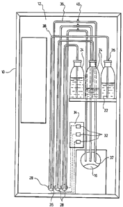
Referring to figure 3, the flavour dispensing mechanism according to one
embodiment of the present invention will now be described in more detail. The
flavour dispensing mechanism (12) includes at least one flavouring liquid
source
(24). Of course, any person versed in the art will appreciate that the flavour
dispensing mechanism (12) may include a number of flavouring liquid sources
CA 02537775 2006-02-27
7
(24). Although three flavouring liquid sources (24) are depicted in the
accompanying drawings, it is understood that the number of sources shown is
purely for illustrative purposes and should not be construed as limitative in
any
way. Any suitable container, for example a plastic bottle, which can
effectively hold
a volume of flavouring liquid (22) may serve as a flavouring liquid source.
The
source (24), or bottle, has an outlet (26) for allowing the outflow of the
flavouring
liquid (22). The outlet may be embodied by something as simple as the opening
in
the neck of a bottle.
As for the flavouring liquid (22), it may be embodied by any appropriate
substance
io that may be added to a coffee beverage. It may be synthetic, i.e.
artificial, or
natural. It may be an aromatic liquid essence or syrup, and may for example
include vanilla extract, chocolate syrup, strawberry cream, rum, etc.
The coffee beverage itself is preferably a neutral, unflavoured base, brewed
from
either fine or coarse grinds to which is dispensed a flavouring liquid (22).
By using
a neutral, unflavoured base, the cost of production is kept low while
optimising the
quality of the coffee beverage by minimising the risk of contamination during
the
coffee-making process.
For each flavouring liquid source (24), the flavour dispensing mechanism (12)
includes drawing means for controllably drawing a metered amount of the
corresponding flavouring liquid (22) from the source (24). The drawing means
preferably include a flow-regulating device, embodied in figure 3 by a pump
(28)
connected between the flavouring liquid source (24) and the input end (35) of
a
delivery tube (36) which has an output end (37) positioned to deliver the
flavouring
liquid to the coffee beverage. The pump (28) therefore draws the flavouring
liquid
(22) from the flavouring liquid source (24) to the delivery tube (36). A
controller
(32), connected to the pump (28), is also provided for actuating the pump (28)
to
deliver the metered amount of the flavouring liquid (22) to the delivery tube
(36). It
will be understood by one skilled in the art that the controller may be
embodied by
CA 02537775 2006-02-27
8
any combination of mechanical and/or electronic components able to operate the
pump (28) to open and close on command. In the illustrated embodiments, the
controller of each pump is embodied by appropriate circuit components on a
single
printed circuit board. Alternatively, separate circuits could embody each
controller.
The controller may incorporate a power supply for the corresponding pump, or
separate power supplies may be provided. The controllers (32) may be
programmed either by the manufacturer or the operator to actuate the drawing
of a
pre-determined metered amount of flavouring liquid (22) from the corresponding
flavouring liquid source (24).
io The flavour dispensing mechanism may further include, for each one of the
flavouring liquid sources (24), a supply tube (38) connected between the
outlet
(26) of the flavouring liquid source (24) and the pump (28). The supply tube
(38) is
preferably made of silicone, for ease of installation (silicone tubing is
generally
easily manipulated) and reduction of cost. In some applications it could also
be
made of plastic or any other appropriate material.
In addition, the flavour dispensing mechanism (12) may include a master
controller
(34), to which is connected the controller associated with each flow-
regulating
device, for directing each controller. It may also supply the necessary power
to
operate the drawing means, as in the case of a pump.
2o For each flavouring liquid source (24), displacing means (embodied by a
vent (40)
in Figure 3) is also provided in the corresponding delivery tube (36) for
displacing
the metered amount of the flavouring liquid in this delivery tube (36), and
are
adapted to prevent dripping of flavouring liquid (22) from the output end (37)
of the
delivery tube (36), apart from delivering the metered amount to the coffee
beverage (20).
To prevent the contamination of successive coffee beverages (20) and thus
assure the taste quality of the coffee beverage, extraneous unwanted drips of
CA 02537775 2006-02-27
9
flavouring liquid between coffee-making processes should be prevented. Of
course, preventing unwanted drips has the added benefit of preventing the mess
caused by such drips. This may be accomplished via the provision of a vent
(40) in
the delivery tube (36), and the proper positioning of these components. The
vent
(40) and delivery tube (36) must be positioned such as to allow the metered
flavouring liquid (22) that has accumulated in the portion of the delivery
tube (36)
immediately descending into the dispensing area (16) to be displaced along the
delivery tube (36), out of the output end (37) of the delivery tube and into
the
coffee beverage (20) located in the dispensing area (16). The vent (40) may be
lo embodied by a tube inserted into an opening provided in the delivery tube
(36).
Preferably, it may be a plastic T-connector tube spliced into the delivery
tube (36)
at a point near where the delivery tube starts to descend toward the
dispensing
area (16). Alternatively, the vent may be incorporated into the flow-
regulating
device. For example, a valve with an integrated vent may be used. One other
option to displace the flavouring liquid in the delivery tube is to use a
peristaltic
pump. A peristaltic pump applies a negative pressure to the delivery tube to
displace the flavouring liquid therein and thereby prevents any unwanted
dripping.
In the embodiment illustrated in Figure 3, a small pump, such as a micro-pump,
is
preferably used as drawing means, to minimise cost and the space taken by the
pump (28). However, the drawback of a micro-pump is its limited pumping power.
As such, to maximise its efficiency, the micro-pump (28) may be placed below
the
flavouring liquid source (22), as shown in Figure 3, to benefit from the added
force
of gravity acting on the flavouring liquid (22) in the supply tube (38). As a
pump
(28) of this type usually remains open, it is possible, under some
circumstances,
that liquid from the flavouring liquid source be drawn out between activations
of
the pump with sufficient pressure to allow it to be pushed along the delivery
tube
(36) and drip out of its output end (37). To prevent such unwanted dripping of
flavouring liquid (22) from the delivery tube (36) apart from delivering the
selected
flavouring liquid to the coffee beverage (20), the delivery tube of this
embodiment
preferably runs up from the pump (28) to a point above the flavouring liquid
source
CA 02537775 2006-02-27
(24) and then turns to run down as directly as possible towards the dispensing
area (16). The vent (40) is spliced into the delivery tube (36) at a point
just before
the delivery tube turns to descend towards the dispensing area (16). In this
way,
any flavouring liquid that accumulates in the portion of the delivery tube
before the
5 turn remains in the delivery tube, the residual pumping pressure on the
liquid
being insufficient to propel the liquid past the turn in the delivery tube,
and
flavouring liquid in the descending portion of the delivery tube after the
turn is
displaced along the delivery tube (36), out of the output end (37) of the
delivery
tube and into the coffee beverage (20) located in the dispensing area (16)
through
io the use of the vent (40). If a peristaltic pump is used instead of a micro-
pump,
there is no need for vent (40) in the delivery tube (36) - the peristaltic
pump itself
preventing any unwanted dripping. Moreover, the delivery tube (36) need not
run
up from the pump (28) to a point above the flavouring liquid source (24) in
this
embodiment.
is In the embodiment illustrated in Figure 4, a sufficiently strong and
efficient pump
(28) is used to draw the flavouring liquid (22) from the flavouring liquid
source (24).
One drawback of such a pump is its relatively elevated cost and bulky volume,
but
it could still be considered for particular applications of the present
invention. The
strong pump (28) may be positioned above the flavouring liquid source (22), as
shown in Figure 4. In this case, to prevent unwanted dripping of flavouring
liquid
(22) from the delivery tube (36, the delivery tube (36) runs from the pump
down to
the dispensing area (16) and the vent (40) is spliced into the delivery tube
(36) at a
point just before the delivery tube turns to descend towards the dispensing
area
(16). Consequently, flavouring liquid that accumulates in the portion of the
delivery
tube before the turn remains in the delivery tube, and flavouring liquid
present in
the descending portion of the delivery tube after the turn is displaced along
the
delivery tube (36), out of the output end (37) of the delivery tube and into
the
coffee beverage (20) located in the dispensing area (16) through the use of
the
vent (40). Again, in the case of a peristaltic pump, there is no vent (40) in
the
3o delivery tube (36) - the peristaltic pump itself preventing any unwanted
dripping.
CA 02537775 2006-02-27
11
In the embodiment illustrated in Figure 5, a valve (30) tapped into the
flavouring
liquid source (24) is actuated by the controller (32) to draw a metered amount
of
flavouring liquid (22) from the flavouring liquid source (24) into the
delivery tube
(36) connected to the valve (30). Unwanted dripping is prevented by providing
a
vent (40) at the junction of the valve (30) with the delivery tube (36). Once
again,
the vent (40) causes the flavouring liquid (22) that may otherwise remain in
the
delivery tube (36) following the dispensing of the flavouring liquid into the
coffee
beverage (20) and drip out at a later time, to be displaced out of the
delivery tube
into the coffee beverage during the actual dispensing process.
to By including a separate delivery tube (36) for each flavouring liquid (22),
the
contamination that would result from using the same tube is circumvented. Like
the supply tube (38), the delivery tube (36) may be made of silicone or
plastic to
facilitate installation and reduce cost. The output end (37) of the delivery
tube (36),
which delivers the flavouring liquid (22) to the coffee beverage (20), may be
ts provided with a nozzle preferably made of stainless steel or rigid plastic.
The
nozzle may serve to better direct and control the flow of flavouring liquid
(22) to the
coffee beverage (20). The nozzle may also advantageously be removable to allow
for cleaning the existing nozzle or replacing the existing nozzle with a new
one.
Referring back to figures 1 and 2, the coffee dispensing machine (10) of the
20 present invention may include selection means by which the consumer may
select
a flavouring liquid (22). The selection means may, for example, be simple
buttons,
a conventional display screen in association with a keypad or a tactile
display
screen (14) that incorporates an electronic keypad into the display screen.
The
buttons may be associated with a particular flavouring liquid and even be used
for
25 portion control. The length of time the user presses a button determining
the
metered amount of flavouring liquid provided. The display screen may display
queries regarding the choice of flavouring liquid. Advantageously, it may be
of a
size to display the entire selection menu at a glance. Typically, the keypad
CA 02537775 2006-02-27
12
transmits the choice information directly to controllers (32) or indirectly
via master
controller (34).
For example, a consumer wanting a flavoured coffee beverage consults the
selection menu presented on the display screen (14) and presses the key
associated with his choice of flavouring liquid (22). The pressed key sends an
electronic signal to the controller (22) associated with the selected
flavouring liquid
(22). The controller (22) in turn actuates the pump (28) or valve (30),
turning the
pump or valve on and then off. While the pump (28) or valve (30) is on,
flavouring
io liquid (22) is drawn from the flavouring liquid source (24) passing through
the
delivery tube (36) and into the receiving cup (18). By actuating the pump or
valve
on and off, a pre-determined metered amount of the flavouring liquid is
delivered
to the receiving cup. Any unwanted extraneous drips are prevented by venting
the
delivery tube (36) via the appropriate positioning of the vent (40) provided.
In accordance with another aspect of the present invention, there is generally
provided a method for incorporating a flavour dispensing mechanism into a
coffee
dispensing machine which includes the steps of:
a. providing at least one flavouring liquid source having an outlet for
outputting
a flow of the flavouring liquid.
This may be accomplished by providing containers holding a volume of the
flavouring liquid and attaching these containers or affixing some supporting
mechanism such as a shelf on which to rest these containers onto the inside of
a
wall or door of the coffee dispensing machine. The containers may be
positioned
such that the outlet is facing the top of the machine or the bottom, dependent
on
the drawing means to be used.
b. providing drawing means for controllably drawing a metered amount of the
flavouring liquid from the source of flavouring liquid.
CA 02537775 2006-02-27
13
For drawing a metered amount of flavouring liquid, a flow-regulating device,
such
as a pump or valve, may be connected to a flavouring liquid source, preferably
via
a supply tube, and to a controller that actuates the flow-regulating device to
draw
the metered flow of flavouring liquid. In the case where the flow-regulating
device
used is a pump, the pump may be placed in a location that optimises its
operation.
A weak pump connected to a flavouring liquid source via a supply tube may be
placed below the flavouring liquid source so as to benefit from the force of
gravity
acting on the flavouring liquid flowing out of the source into the supply
tube, and
1o thus, increase its drawing efficiency. A strong pump may be placed above or
below the flavouring liquid source, whichever location best suits the
incorporation
method. In the case where the flow-regulating device is a valve, the valve may
be
tapped into the bottoming-facing outlet of the flavouring liquid source.
c. connecting an input end of a delivery tube to the drawing means for
receiving
the metered amount of the corresponding flavouring liquid, and providing an
output end opposite the input end of the delivery tube for delivering the
metered amount of flavouring liquid to a coffee beverage.
2o The input end of the delivery tube may be connected to a pump or valve by
conventional connectors. The delivery tube may be then affixed to the wall or
door
of the coffee machine using appropriate holders such as clamps.
d. providing displacing means for displacing the metered amount of the
flavouring liquid in the delivery tube, the displacing means adapted to
prevent
dripping of the flavouring liquid from the output end of the delivery tube
apart
from delivering the metered amount of flavouring liquid to the coffee
beverage.
3o This may be accomplished by using a vent as the displacing means, that is,
by
inserting a small tube into an opening provided in the delivery tube.
Preferably, it
CA 02537775 2006-02-27
14
may be a plastic T-connector tube spliced into the delivery tube. The vent
should
be located in such a position as to allow the metered flavouring liquid that
has
accumulated in the portion of the delivery tube immediately descending into
the
dispensing area to be displaced along the delivery tube, out of the output end
of
the delivery tube and into the coffee beverage located in the dispensing area.
Preferably, the vent is positioned at the location of the highest point of the
delivery
tube, just before the highest turning point of the delivery tube - near where
the
delivery tube starts to descend toward the dispensing area. Alternatively, a
valve
with the vent located at the junction of the valve with the delivery tube or
valve with
io an integrated vent may be used. Another option would be to use a
peristaltic
pump which encompasses the displacing means, and in this way forego the use of
a vent altogether.
The method above may further include the step of:
e. providing selection means for selecting a flavouring liquid, the selection
means being in communication with the drawing nieans.
This may be accomplished by providing buttons associated with a particular
flavouring liquid. The selection signal is transmitted to the pump or valve
and used
for portion control. Alternatively, a conventional display screen in
association with
a keypad or a tactile display screen connected to the controller directly, or
indirectly via the master controller, may be used. The selection signal
transmitted
from the keypad is transmitted to the controller which then actuates the pump
or
valve.
The method above may be implemented by adapting the flavour dispensing
machine within a door of the coffee machine. This may be accomplished by
simply
affixing the components of the flavour dispensing mechanism to the inside of
the
door of the coffee dispensing machine, for example by using clamps or clips.
CA 02537775 2006-02-27
Numerous modifications could be made to any of the embodiments described
above without departing from the scope of the present invention as defined in
the
appended claims.
5