Note: Descriptions are shown in the official language in which they were submitted.
CA 02537839 2006-03-03
WO 2005/080035 PCT/US2003/027485
TOOL APPARATUS
BACKGROUND
Tool holders are used in various machine tools, such as turning centers and
lathes, for
the purpose of holding a variety of different tools such as boring bars.
Boring bars are
typically used by a turning center machine tool during a boring operation, the
purpose of
which is to increase the size of a pre-existing internal features of a
workpiece while obtaining
target size and surface finish accuracy. Under very rigid tool setups, boring
operations are
often capable of maintaining a size tolerance within 0.0002".
A turning center machine tool includes a workpiece spindle for holding and
spinning
a workpiece, and may further include a tool spindle, tail-stock, or tool
turret for holding a tool
holder and tool. A tailstock typically includes a socket into which a rearward
end of the tool
holder is inserted. Some tool holders have a generally cylindrical shank that
extends forward
from the rearward end and that includes one or more longitudinal flats for
orienting the tool
holder within the tailstock socket and for use with a setscrew fastening
arrangement. The
shank typically terminates at a mounting flange for axially locating the tool
holder against an
outboard face of the machine tool tailstock. Forward of and adjacent the
mounting flange
there is provided a set screw diameter through which set screws radially
extend and intersect
with a tool bore that axially extends through the tool holder for accepting a
boring bar
therein.
The boring bar is typically a generally cylindrical tool having a fastening
end that
inserts into the tool bore of the tool holder. Extending forward from the
fastening end, the
CA 02537839 2006-03-03
WO 2005/080035 PCT/US2003/027485
boring bar includes a solid shank having one or more longitudinal flats
against which the tool
holder set screws are fastened for holding the boring bar within the tool bore
of the tool
holder. Extending further forward, and opposite the fastening end, the boring
bar terminates
in a seat portion into which a cutting insert fastens.
The distance between the tip of the cutting insert and an outboard face of the
set screw
diameter of the tool holder defines what is known as the unsupported overhang
of the boring
bar. In general, the greater the ratio between the length of the unsupported
overhang to the
diameter of_ the boring bar -- the lesser the rigidity of the tool setup.
Lesser tool rigidity
results in tool vibration and chatter, thereby necessitating reductions in
machining feedrates
and throughput in order to maintain workpiece accuracy and surface finish.
Boring of workpieces having stepped diameters, or variably sized internal
features,
presents a special problem for boring tools. A stepped diameter workpiece is
one having a
shallower, larger diameter and one or more deeper, smaller diameters. The
shallower, larger
diameter of the workpiece is relatively proximate the tool holder, thereby
requiring very little
unsupported overhang of the tool and permitting a more rigid and larger
diameter boring bar
to be used. Thus, the shallower, larger diameter can often be cut relatively
quickly and
accurately due to the rigidity of the tool setup. In contrast, the deeper,
smaller diameters are
relatively distal the tool holder, thereby necessitating longer unsupported
overhang and
smaller diameter of the boring bar.
To reach the deeper, smaller diameters, the machining process must be
interrupted to
change from a rigid, larger diameter boring bar to a smaller diameter boring
bar having a
longer unsupported overhang. Such an interruption is a major risk to workpiece
accuracy for
2
CA 02537839 2006-03-03
WO 2005/080035 PCT/US2003/027485
at least a couple of reasons. First, using a smaller diameter boring bar
sacrifices tool rigidity
due to a corresponding decrease in cross-sectional surface area and beam
strength of the tool.
Second, a tool change disrupts the dimensional relationship between the
shallower, larger
diameter and the deeper, smaller diameter since two different tools must be
used. Simply put,
using two different tools is undesirable since the subsequent tool will not
necessarily pick up
exactly where the original tool left off in the cut. Conversely, it is
desirable to use the same
single tool to cut both diameters to maintain continuity of the cut and
thereby more strictly
maintain the dimensional relationship between the diameters.
Moreover, using two different tools results in increased manufacturing time
and costs.
First, interrupting the machining operation to execute a tool change results
in increased
machine cycle time. Second, the deeper, smaller diameters must be cut
magnitudes more
slowly than the shallower, larger diameters. Slow machining is necessary to
maintain the
same size accuracy throughout the workpiece when cutting the workpiece with
the smaller
diameter boring bars having long unsupported overhangs. In a manufacturing
environment,
every second of cycle time is accounted for. Thus, where time is money,
unnecessarily slow
machining performance translates into unnecessarily high manufacturing costs.
Another special problem with boring involves the interconnection of carbide
boring
bars to boring bar tool holders. Carbide boring bars are cylindrical and have
longitudinal
flats extending therealong to facilitate setscrew fastening to a respective
tool holder. The
longitudinal flats present two problems. First, incorporating longitudinal
flats along a boring
bar yields less tool rigidity. The longitudinal flats require a loss in cross-
sectional area and
beam strength. Second, setscrews do not always squarely engage the
longitudinal flats of the
boring bar despite being tightly fastened down. In other words, the boring bar
can be clocked
3
CA 02537839 2007-02-19
such that the flats become out of square with the set screws, wherein the
boring bar can work
loose from engagement with the set screws during machining operations. Third,
setscrews only
engage a small area of the boring bar roughly equal to the diameter of the
point of the setscrew.
The above problems manifest themselves in the form of unnecessarily
compromised rigidity of
the boring bar tool setup, and an attendant decrease in workpiece quality
and/or increase in
machining time and cost.
BRIEF SUMMARY OF THE INVENTION
According to one embodiment of the present invention, there is provided a
cutting tool
apparatus having a shank and a tool support extension disposed longitudinally
adjacent the shank
and extending in a direction distal the shank, wherein the tool support
extension includes an
incurvate taper profile.
Thus in one aspect, the invention provides a cutting tool apparatus
comprising:
a shank; and
a tool support extension disposed longitudinally adjacent said shank and
extending in a direction distal from said shank, said tool support extension
comprising an
incurvate taper profile.
In another aspect, the invention further provides means for fastening the
cutting tool to a
tool extension portion, said means for fastening the tool apparatus as claimed
in claim 1, further
comprising means for fastening said cutting tool to a tool extension portion,
and said means for
fastening comprises at least one of the following:
a set screw threaded through said tool extension portion in an orientation
substantially
square to said longitudinal dove-tail portions; and
at least one band clamp fastening to said tool extension portion such that
said cutting tool
is trapped between said at least one band clamp and said tool extension
portion.
In yet another aspect, there is provided a tool apparatus comprising:
a shank; and
4
CA 02537839 2007-02-19
a tool support extension disposed longitudinally adjacent said shank and
extending in a
direction distal from said shank, said tool support extension comprising at
least a portion being
sector-shaped in transverse cross section.
In another aspect, there is provided a tool kit comprising:
at least one common cutting tool; and
a plurality of tool holders, each of said tool holders comprising:
a shank; and
a tool support extension longitudinally adjacent said shank, said tool support
extension
comprising a portion having at least one of a tapered sector extension and an
incurvate-tapered
extension; and
means for mounting said cutting tool to said tool support extension.
BRIEF DESCRIPTION OF THE SEVERAL VIEWS OF THE DRAWINGS
Features and advantages of the present invention will become apparent to those
skilled in
the art from the following description with reference to the drawings, in
which:
FIG. 1 is an exploded perspective view of a tooling apparatus according to a
first
embodiment of the present invention;
FIG. 2A is a perspective view of a boring bar of the tooling assembly of FIG.
1;
FIG. 2B is a perspective view of the underside of the boring bar of FIG. 2A;
4A
CA 02537839 2006-03-03
WO 2005/080035 PCT/US2003/027485
Fig. 3 is a perspective view of a tool holder of the tooling assembly of Fig.
1;
Fig. 4 is a longitudinal cross-sectional view of the tool holder of Fig. 3;
Fig. 5 is a perspective view of the tooling apparatus of Fig. 1, as assembled;
Fig. 6 is a perspective view of a tool holder according to a second embodiment
of the
present invention;
Fig. 7 is a longitudinal cross-sectional view of the tool holder of Fig. 6;
Fig. 8 is a forward end view of the tool holder of Fig. 6;
Fig. 9 is a perspective view of a tool holder according to a third embodiment
of the
present invention;
Fig. 10 is a longitudinal cross-sectional view of the tool holder of Fig. 9;
Fig. 11 is a forward end view of the tool holder of Fig. 9;
Fig. 11A is a forward end view of a tool holder according to a fourth
embodiment of
the present invention;
5
CA 02537839 2006-03-03
WO 2005/080035 PCT/US2003/027485
Fig. 12 is a perspective view of a tooling kit according to a fifth embodiment
of the
present invention;
Fig. l3A is a perspective view of a tool apparatus according to a sixth
embodiment of
the present invention;
Fig. 13B is a side view of the tool apparatus of Fig. 13A;
Fig. 14A is a perspective view of a tool apparatus according to a seventh
embodiment
of the present invention;
Fig. 14B is a longitudinal cross-sectional view of the tool apparatus of Fig.
14A; and
Fig. 15 is a longitudinal cross-sectional view of a tool apparatus according
to an
eighth embodiment of the present invention.
DETAILED DESCRIPTION OF THE INVENTION
The present invention is not limited in its application to the details of any
particular
arrangement described or shown, since the present invention is capable of
multitudes of
embodiments without departing from the spirit and scope of the present
invention. First, the
principles of the present invention are described by referring to only a few
exemplary
embodiments for simplicity and illustrative purposes. Although only a limited
number of
embodiments of the invention are particularly disclosed herein, one of
ordinary skill in the art
would readily recognize that the same principles are equally applicable to,
and can be
6
CA 02537839 2006-03-03
WO 2005/080035 PCT/US2003/027485
implemented in all types of tooling. Furthermore, numerous specific details
are set forth
below and in the drawing figures to convey with reasonable clarity the
inventor's possession
of the present invention, descriptions of how to make and/or use the present
invention, and
the best mode in carrying out the present invention known to the inventor's at
the time of
application. It will, however, be apparent to one of ordinary skill in the art
that the present
invention may be practiced without limitation to these specific details. In
other instances,
well known methods and structures have not been described in detail so as not
to
unnecessarily obscure the present invention. Finally, the tenninology used
herein is for the
purpose of description and not of limitation. Thus, the following detailed
description is not to
be taken in a limiting sense and the scope of the present invention is defined
by the claims
and their equivalents.
Generally shown in the Figures, a tool apparatus is presented in accordance
with the
present invention. The phrase tool apparatus means tooling assemblies, tool
holders, tool
bars, cutting tool inserts, and the like. The phrase tool holder means any
device or article for
holding another tool apparatus and is synonymous with tool bushing, collet,
collar, sleeve,
and the like. Finally, the various embodiments described below share many
common features
and characteristics that need not be discussed for each and every embodiment
to avoid
unnecessary repetition.
Referring now in detail to the Figures of the present invention, there is
shown in
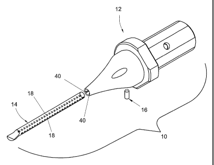
Figure 1 an exploded view of a tooling assembly 10 that generally includes a
tool holder 12, a
cutting tool such as a boring bar 14, and a set screw 16 for fastening the
boring bar 14 within
the tool holder 12.
7
CA 02537839 2006-03-03
WO 2005/080035 PCT/US2003/027485
Referring now to Figures 2A and 2B, the boring bar 14 can be composed of any
suitable material for machining, including high speed steel, carbide, and the
like. For
example the boring bar 14 can be a 3/8" diameter bar available from CARBOLOY,
part
number A06-SCLPR2. As best shown in Figure 2B, the boring bar 14 includes a
longitudinal
female dovetail grooves or features 18 for interlocking engagement into the
tool holder 12 as
will be described further below. As defined herein, dovetail features
encompass any
substantially longitudinally disposed interlocking features such as dovetails,
splines,
keyways, and the like. The dovetail features 18 can be integrally formed in
the boring bar 14
during manufacture thereof. Otherwise, the dovetail feature 18 can be milled
into the boring
bar 14 as an independent operation subsequent to creation of the boring bar 14
itself, such as
with a 0.370" radius dovetail cutter. It is contemplated that the boring bar
14 can be used
without a cutting insert (not shown) or can be adapted for use with a cutting
insert. Tools
other than a boring bar 14 could be substituted for use in the present
invention such as a drill,
reamer, end mill, and the like.
In reference to Figure 3, the tool holder 12 can be composed of any material
suitable
for machining including high-speed steel. The tool holder 12 includes a shank
20 that is
generally cylindrical in shape and that has one or more longitudinal flats 22
for a setscrew
fastening arrangement with a machine tool (not shown). The shank 20 also
includes a coolant
inlet 24 that is transversely drilled therein. The shank 20 extends
longitudinally forward from
a rearwardly disposed mounting end 26 and terminates at a locating shoulder
28.
Referring now to Figures 3 and 4, a tool support extension 30 originates
longitudinally adjacent the shank 20, includes a mounting flange 32, and is
cantilevered from
the shank 20 when the shank 20 is held by a machine tool. As such, the tool
support
8
CA 02537839 2006-03-03
WO 2005/080035 PCT/US2003/027485
extension 30 is basically a cantilevered beam that is used to support the
boring bar 14 of
Figure 2. As shown in Figure 3, the tool support extension 30 is integral with
the shank 20 as
opposed to being a separate part, as will be described with respect to Figure
15 below. One
of ordinary skill in the art will recognize that the locating shoulder 28 and
flange portion 32
are not necessary to the present invention, such that the novel aspects of the
tool support
extension 30 of the present invention could be incorporated in a flangeless
tool or tool holder.
Here, the tool support extension 30 of all of the embodiments is inclusive of
structure that is
forward of and adjacent the shank 20. The tool support extension 30 extends
forward from a
position longitudinally adjacent the shank 20 'and terminates in a forward
tool end 34 -
specifically shown here in the shape of a frusto-conical tip.
The tool support extension 30 is shaped as a substantially circumferentially
full cone
or taper that reduces along a direction toward the forward tool end 34. In
other words, the
tool support extension 30 is declivitive in a forward extending direction to
define a declivitive
profile 36. The declivitive profile 36 of the tool support extension 30 can be
excurvate/convex, straight, incurvate/concave, or any other geometry designed
for workpiece
clearance. As shown here, the declivitive profile 36 is incurvate in shape,
which is conducive
to optimum workpiece clearance during machining operations. In other words,
the tool
support extension 30 includes unique tool geometry for reaching deeply into a
workpiece (not
shown) with minimal tooling interference with the workpiece. Accordingly, the
tool support
extension 30 maximizes extended tool support while it minimizes tool holder
mass, thereby
yielding an optimal tight-spaced tool solution such as for boring of stepped
diameter
workpieces. It is contemplated that portions of the tool support extension 30,
particularly
those portions nearest the forward tool end 34, can be relieved for additional
workpiece
9
CA 02537839 2006-03-03
WO 2005/080035 PCT/US2003/027485
clearance. Such relief can be machined into the tool support extension 30 or
can be a void
formed in the tool support extension during manufacturing thereof.
The tool holder 12 further includes a tool bore 38 extending centrically, or
on-center,
therethrough. The tool holder 12 includes a male dove-tail feature 40 that
longitudinally
extends along the tool bore 38 for engagement with the female dove-tail
feature 18 of the
boring bar 14 of Fig. 2. It is contemplated that the male dovetail feature 40
could be provided
on the boring bar 14 instead of the tool holder 12, and vice-versa. The male
dovetail feature
40 of the tool holder 12 can be machined therein, for example with a broaching
tool or the
like. Referring to Figure 4, a setscrew hole 42 extends transversely through a
portion of the
tool support extension 30 to accept the setscrew 16 shown in Figure 1.
Referring back to Figure 1, the setscrew 16 is aligned squarely to the mating
surfaces
of the respective dovetail features 18 and 40 of the boring bar 14 and tool
support extension
30. Additional setscrews and holes could be provided in various longitudinal
locations along
the tool support extension 30 for additional holding power of the boring bar
14 within the tool
holder 12. A coolant outlet 44 is drilled longitudinally through the tool
holder 12 to intersect
with the transversely drilled coolant inlet hole 24. As is apparent from
Figure 3, the unique
tool support extension enables the coolant outlet hole 44 to be positioned
much closer to a
workpiece compared to prior art tool holder designs.
As shown in Figure 5, the boring bar 14 inserts longitudinally into the tool
holder 12,
and the set screw 16 of Figure 1 threads into the tool holder 12 to fasten the
boring bar 14
within the tool holder 12 to yield the tooling assembly 10 of the present
invention. As such,
the boring bar 14 can be positioned as shown within the tool support extension
30 for
CA 02537839 2006-03-03
WO 2005/080035 PCT/US2003/027485
increased tool rigidity, or the boring bar 14 can be extended longitudinally
forward from the
shown position for increased tool reach and workpiece clearance. In any case,
such a tooling
assembly 10 is typically used with a turning center machine tool (not shown)
wherein the
mounting end 26 of the tool holder 12 is inserted into a tailstock or tool
spindle of the
machine tool.
Referring again to Figure 1, the present invention provides a tool holding
structure
that is substantially more rigid than that of existing tool holders. The
present invention
provides a novel and unobvious tool support extension 30 that is relatively
long, slender, and
uniquely shaped for entering the interior of a workpiece during a cut under
minimal
workpiece interference. The unique incurvate shape of the tool support
extension 30 permits
optimal tool support and reach while ensuring optimized clearance between the
tool holder 12
and a workpiece.
The present invention also provides a unique and substantially more rigid
interconnection of a substantially cylindrical boring bar 14 to a tool holder
12. To begin
with, the longitudinal dovetail feature,s 18, rather than longitudinal flats,
yield a boring bar
with relatively more substantive cross-sectional area and thus greater beam
strength and
rigidity. This is because longitudinal dovetail features require relatively
little of the circular
cross section of the boring bar 14 to be removed. In contrast, using
longitudinal flats
generally requires relatively more material to be removed from the boring bar
14. Moreover,
the dovetail features 1 S provide close interlocking engagement over a greater
length of the
boring bar 14 compared to prior art designs. For example, with setscrew and
longitudinal flat
designs, the engagement area is limited only to where the setscrew engages the
flat of the
boring bar (not shown). In other words, the present invention provides a more
continuous
11
CA 02537839 2006-03-03
WO 2005/080035 PCT/US2003/027485
engagement area between the boring bar 14 and tool holder 12, whereas prior
art designs
provide only a very discrete amount of engagement area.
Additionally, dovetail engagement of a cylindrical tool within a tool holder
bore
solves the clocked boring bar / jammed setscrew condition described in the
background
section. Use of closely mating dovetail features 18, as with the present
invention, precludes
the possibility that the boring bar 14 becomes clocked within the tool holder
12, thereby
minimizing the possibility that the boring bar 14 could work itself loose
under vibrations
during machining.
Figures 6 through 8 illustrate a tool holder 112 in accordance with another
embodiment of the present invention. This tool holder 112 is largely
consistent with the
embodiment described above with a few exceptions. As best shown in Figure 6,
the tool
holder 112 includes a shank 120 with flats 122 and a coolant inlet 124 wherein
the shank 120
terminates at a locating shoulder 128. Longitudinally adjacent the shank 112
is a tool support
extension 130 including a mounting flange 132 and setscrew diameter 133 having
a threaded
setscrew hole 142. Again, a coolant outlet 144 is provided, but here the
coolant outlet 144 is
not positioned at an extended forward location as with the previous
embodiment.
As best shown in the front-end view of Figure 8, the tool holder 112 includes
the tool
support extension 130 having a sector extension 150 that is uniquely shaped
for supporting
the boring bar 14 of Figure 2 within and on the tool holder 112. Unlike the
circumferentially
full tool support extension 30 of Figure 3 of the previous embodiment, this
tool support
extension 130 includes the sector extension 150 that is sector-shaped such
that the sector
extension 150 occupies only a partial radian range of the circumference of the
tool holder
12
CA 02537839 2006-03-03
WO 2005/080035 PCT/US2003/027485
112, as best shown in the end view of Figure 8. A sector is sometimes defined
as a portion of
a circle that is bounded by two radii and an arc joining the end points of the
two radii. Here,
however, sector is more broadly defined as any portion of a circle that is
less than a full
circle, such that the boundaries need not consist of radii and an arc. Rather,
under the
definition of sector according to the present invention, the boundaries can be
lines and the
like that do not pass through the center of a circle, as shown in Figure 8.
The sector
extension 150 of Figure 8 occupies only about a 45 wide sector of the
circumference of the
tool holder 112. The sector 150 could vary in size from as little as 1 up to
the 360 fully
circumferential tool support extension of the previous embodiment. The sector
extension 150
has a flat top 152 and sides 154, with an incurvately tapered underside 156
for workpiece
clearance.
As best shown in Figure 7, the tool holder 112 includes a shank 120 that is
generally
cylindrical in shape and that has one or more longitudinal flats 122. The
shank 20 extends
longitudinally forward from a rearwardly disposed mounting end 126 and
terminates at a
locating shoulder 128. A tool bore 138 is provided along and through the tool
support
extension 130. Along the sector extension 150, the tool bore 138 is
circumferentially open.
As such, the tool bore 138 is defined herein as encompassing both an open
portion and a
circumferentially enclosed portion. The tool support extension 130 includes
male dove-tail
tongues or features 140 that longitudinally extend along the tool bore 138 for
interlocking
engagement with the female dove-tail features 18 of the boring bar 14 of
Figure 2, as also
shown in the cross-sectional view of Figure 7. The tool bore 138 is provided
along a central
longitudinal axis of the tool holder 112 such that the tool bore 138 is
centrically positioned,
or on-center with respect to the tool holder 112. Again, the dovetail feature
140 can be
machined into the tool holder 112 by broaching, by milling, or the like. A
setscrew hole 142,
13
CA 02537839 2006-03-03
WO 2005/080035 PCT/US2003/027485
(or a series of set screw holes) can be provided anywhere along the length of
the tool support
extension 130. Thus, additional setscrews can be fastened into the tool holder
112 for extra
tool support and rigidity.
Another embodiment of the present invention includes a tool holder 212 as
shown in
Figures 9 through 11. As shown in Figures 9 and 10, the tool holder 212 is
substantially
similar to the previously described embodiment witli the exception that a tool
bore 238 is
radially offset from the central longitudinal axis of the tool holder 212 such
that the tool bore
238 is not on-center. In other words, the tool bore 238 is eccentrically
positioned. This
unique geometry provides additional tool holder mass and beam strength to
support the
boring bar 14 of Figure 2.
As with the previous embodiment, the tool holder 212 includes a shank 220 that
is
generally cylindrical in shape and that has one or more longitudinal flats
222. The shank 220
extends longitudinally forward from a rearwardly disposed mounting end 226 and
terminates
in a+locating shoulder 228. A tool support extension 230 is integral with the
shank 220 and
originates longitudinally adjacent the shank 220, includes a mounting flange
232, and is
cantilevered from the shank 220 when the shank 220 is held by a machine tool.
The tool
support extension 230 includes a sector extension 250 having a declivitive
profile 236 that is
incurvately tapered for workpiece clearance, as best illustrated in Figure 10.
As best shown
in Figure 11, the tool support extension 230 includes sides 254 that are not
straight as with
the previous embodiment, but rather are curved such that the tool support
extension 230 is
substantially elliptical in cross-sectional shape.
14
CA 02537839 2006-03-03
WO 2005/080035 PCT/US2003/027485
Figure 11A illustrates a front-end view of a tooling assembly 310 that
incorporates a
boring bar 314 into a tool holder 312 wherein the tool holder 312 is a slight
variation on the
embodiment of Figures 9 through 11. In contrast to the vertically oriented
sector extension
250 depicted in Figure 11, here a sector extension 350 is oriented obliquely
with respect to
vertical. In transverse cross-section, the sector extension 350 can take any
shape including
elliptical, semi-elliptical, and the like. As with the other embodiments, the
sector extension
350 includes a declivitive profile 336 that is incurvately shaped for
workpiece clearance.
The sector extension 350 is strategically oriented at about a 45 angle from
vertical so
as to squarely oppose resultant cutting forces acting on a cutting insert 315
of the boring bar
314. The resultant cutting forces arise from the vertical or tangential
cutting forces FT due to
rotation of the workpiece (not shown) into the cutting insert 315, and from
the horizontal or
radial cutting forces FR due to the feed of the cutting insert 315 into the
workpiece. Thus, the
mass of the sector extension 350 can be further minimized for better workpiece
clearance, by
calculating the resultant cutting force magnitude and direction and thereby
predetermining
the optimum angle and size for the oblique sector extension 350.
Another embodiment of the present invention involves a tooling kit 400. The
kit 400
includes a relatively small diameter boring bar 414 of 1/4" diameter for
example, and several
different tool holders 412a - 412c of varying proportion but common tool bore
diameter, and
according to the inventive features of the present invention. As shown, the
kit 400 includes
the three tool holders 412a - 412c distinguished by the proportion of the
length (L) of each
tool support extension 430a - 430c to the diameter (D) of each respective
shank 420a - 420c.
Here, the tool holders 412a - 412c have L:D ratios including 1:1, 1:2, and 1:3
respectively.
CA 02537839 2006-03-03
WO 2005/080035 PCT/US2003/027485
The kit 400 includes the features of the above-described embodiments. For
example,
the boring bar 414 includes the dovetail features 418 for interlocking
engagement with each
of the tool holders 412a - 412c. In turn, each of the tool holders 412a - 412c
include the
inventive features described with respect to the embodiment of Figures 9-11.
For example,
dovetail features 440a - 440c are provided in the tool support extensions 430a
- 430c for
interlocking with the boring bar 414. Also, the tool support extensions 430a -
430c include a
declivitive profiles 436a - 436c of incurvate shape for workpiece clearance.
The kit 400 can
include any quantity and combination of variously sized boring bars and tool
holders.
The kit 400 solves an expensive problem for machinists. It is common for a
machinist
to use several different diameter boring bars to cut different features of a
workpiece. This is
done to optimize rigidity and machining speed for shallower, larger cuts and
provide
sufficient tool reach and workpiece clearance for deeper, smaller cuts.
However, this practice
is relatively expensive since it necessitates keeping several expensive and
differently sized
boring bars on hand. Alternatively, some machinists make a practice of buying
one relatively
large boring bar and snag grinding the boring bars for clearance as needed.
Such a practice is
destructive to the boring bar and results in a rigidity compromised tool.
Using the kit 400, however, a machinist can use the single boring bar 414 to
cut a
single workpiece and strategically select from the various tool holders 412a -
412c that best
optimize tool rigidity and workpiece clearance for a particular cut. Such a
solution is
economical because a machinist need not keep on hand several expensive boring
bars of
varying diameter. Rather, the machinist need have only one common diameter
boring bar
and select among several relatively inexpensive tool holders.
16
CA 02537839 2006-03-03
WO 2005/080035 PCT/US2003/027485
This kit solution provides a machinist the flexibility to customize the
tooling assembly
at the machine tool either by selecting a different proportion tool holder
and/or sliding the
boring bar in an out of the tool holder for more or less workpiece clearance.
There is no need
for keeping several expensive boring bars nor for trial and error snag
grinding of a single
large boring bar. Moreover, a machinist need not cobble or modify an existing
tool to
achieve workpiece clearance and tool rigidity. Rather, a machinist need only
select among
various tool holders of different proportion and adjust the length of a boring
bar therein to
achieve optimal workpiece clearance and tool rigidity.
Figures 13A and 13B illustrate a further embodiment of the present invention
wherein
it is contemplated that a tool holder 512 of the present invention can hold a
cutting insert 515
directly without using an intermediate boring bar (not shown). As illustrated
in Figure 13A,
the tool, holder 512 includes a shank 520, tool support extension 530, a
mounting flange 532,
and sector extension 550. As shown in Figure 13B and like the previously
described
embodiments, the tool holder 512 includes a declivitive profile 536 having an
incurvate
tapered shape for optimal workpiece clearance. This tool holder 512 can be
used in
machining applications where a boring bar is unnecessary or undesired, yet the
rigidity and
unique clearance geometry of the present invention is needed.
Figures 14A and 14B illustrate a tooling assembly 610 according to another
embodiment of the present invention. A tool holder 612 includes a shank 620
that is
generally cylindrical in shape and that has one or more longitudinal flats
622. The shank 620
extends longitudinally forward from a rearwardly disposed mounting end 626 and
terminates
at a locating shoulder 628. A tool support extension 630 originates
longitudinally adjacent
the shank 620 and includes a mounting flange 632.
17
CA 02537839 2006-03-03
WO 2005/080035 PCT/US2003/027485
A boring bar 614 is slidably disposed within a tool bore 638 that is
eccentrically
positioned with respect to the central longitudinal axis of the tool holder
612. The boring bar
614 is longitudinally adjustable within the tool bore 638 such that the tool
reach or overhang
can be lengthened or shortened. Unlike the boring bar depicted in the previous
embodiments,
this boring bar 614 does not include a dove-tail feature. Therefore, this
embodiment of the
present invention can be used independently of the unique dove-tailed
cylindrical boring bar
feature and can thus be used with off-the-shelf boring bars.
The boring bar 614 can be fastened to the tool holder solely by set screws or,
as
shown, the boring bar can be additionally fastened to the sector extension 650
of tool holder
612 by one or more band clamps 670 or similar attachment devices. As shown,
the band
clamp 670 circumscribes the boring bar 614 and a portion of the sector
extension 650 to
fasten the boring bar 614 to the tool holder 612.
As best shown in Figure 14B, the sector extension 650 of the tool support
extension
630 tapers forward from shoulder 628 in the form of a declivitive profile 636
of incurvate
shape. The sector extension 650 terminates in a fastening extension 652. The
band clamp
670 circumscribes the fastening extension 652 and the boring bar 614 to hold
the boring bar
614 to the tool support extension 630. The band clamp 614 is contemplated to
be a high-
strength clamp or ring such as is readily available from the OETIKER
Corporation.
Finally, Figure 15 illustrates a tooling assembly 710 according to another
embodiment
of the present invention. Here, the tooling assembly 710 includes a two-piece
tool holder
defined by forward portion 712a and rearward portion 712b. The tool holder
includes a
18
CA 02537839 2006-03-03
WO 2005/080035 PCT/US2003/027485
shank 720 and a tool support extension 730 attached thereto. The shank can be
a modified
3/8" internal diameter tool holder available from MAZAK. And the tool support
extension
730 is a specially fabricated detail composed of high speed steel or the like.
A male
mounting flange 732 on the rearward portion 712b of the tool holder mounts
inside a female
mounting flange 731 on the forward portion 712a of the tool holder, wherein
both mounting
flanges 731 and 732 are fastened together by cap screw fasteners. 713 that
slip through
portions of the female mounting flange and thread into the male mounting
flange as shown.
Alternatively, the fasteners 713 can be bolts, rivets, dowel pins, or the
like. Other fastening
arrangements are contemplated such as a threaded or splined interconnection
between the
mounting flanges 731 and 732.
Still referring to Figure 15, a boring bar 714 is fastened to the tool holder
712a and
712b using the set screw and dove-tail fastening arrangement described with
respect to many
of the embodiments above. Accordingly, set screws 716 thread 'into portions of
the forward
portion 712a of the tool holder. This embodiment provides a simple and cost
effective
modification to off-the-shelf tool holders in order to achieve the many
benefits of the present
invention as further described below.
While the present invention has been described in terms of a limited number of
embodiments, it is apparent that other forms could be adopted by one skilled
in the art. In
other words, the teachings of the present invention encompass any reasonable
substitutions or
equivalents of claim limitations. For example, the structure, materials,
sizes, and shapes of
the individual components could be modified, or substituted with other similar
structure,
materials, sizes, and shapes. Specific examples include using different
engagement geometry
between the boring bar and tool holder and varying the specific geometry of
the tapered
19
CA 02537839 2006-03-03
WO 2005/080035 PCT/US2003/027485
portion of the tool holder. Any geometry of the tapered portion of the tool
holder that
effectuates the purposes described herein is well within the scope and
contemplation of the
present invention. Those skilled in the art will appreciate that other
applications, including
those outside of the machining industry, are possible with this invention.
Accordingly, the
present invention is not limited to only cylindrical boring or machining in
general.
Accordingly, the scope of the present invention is to be limited only by the
following claims.