Note: Descriptions are shown in the official language in which they were submitted.
CA 02537951 2011-03-30
1
CATHETER TIP
BACKGROUND OF THE INVENTION
This invention relates generally to catheters, and more specifically to an
assembly and method that may be used for delivering and deploying one or more
implantable medical devices, such as a stents, grafts, stent-grafts, vena cava
filters, or
other implantable medical devices, hereinafter referred to collectively as
stents, within a
body lumen.
Guide catheters and diagnostic catheters are well known for use in the
performance of medical procedures, such as coronary catheterization,
angiography,
angioplasty, and other diagnostic or interventional procedures, such as
interventional
radiology. Guide catheters aid in treatment of arterial lesions by providing a
conduit for
positioning dilatation balloon systems across an arterial stenosis. Guide
catheters and
diagnostic catheters work with various assemblies for performing other
medical,
therapeutic, and diagnostic procedures, such as dye delivery, arterial
flushing, or arterial
pressure monitoring.
Stents and stent delivery assemblies are utilized in a number of medical
procedures and situations, and as such their structure and function are well
known. A
stent is a generally cylindrical prosthesis introduced via a catheter into a
lumen of a
body vessel in a configuration having a generally reduced diameter and then
expanded
to the diameter of the vessel. In its expanded configuration, the stent
supports and
reinforces the vessel walls while maintaining the vessel in an open,
unobstructed
condition.
Self-expanding, inflation expandable and hybrid stents are well known
and widely available in a variety of designs and configurations. Examples are
disclosed
in US 6348065, US 2002-0055770-Al and US 6168621. Inflation expandable stents
are crimped to a reduced diameter configuration about the delivery catheter,
then
maneuvered to the deployment site and expanded to the vessel diameter by fluid
inflation of a balloon positioned underneath the stent on the delivery
catheter.
In advancing an inflation expandable stent through a body vessel to the
deployment site, there are a number of important considerations. The stent
must be able
to securely maintain its axial position on the delivery catheter. The stent
and inflation
CA 02537951 2011-03-30
2
balloon in the reduced state must have a sufficiently small outer diameter to
allow the
catheter to be advanced through a tortuous anatomy into a desired location of
a body
lumen, such as an artery or other vessel. Further, advancement of the stent
through the
vessel is enhanced by increased flexibility of the stent and catheter tip at
the catheter
distal end. Radiopaque markers on the stent and/or catheter aid in precisely
positioning
the stent at the deployment site.
Delivery catheters, such as disclosed in US 6007543, are known in the
art. Such catheters may include radiopaque markers and stent securement rings
as
disclosed in US 6530947, US 6315790 and US 6395008.
Current methods of assembling balloon catheters typically include
several steps. Often times the catheter shaft is constructed by extruding one
or more
portions of the catheter shaft which are then assembled together with other
components
such as radiopaque markers, securement rings, etc. An inflation balloon is
then
positioned over and/or adjacent to the markers and securement rings and bonded
to the
shaft. In some cases, the distal tip or end region of the catheter may be
provided with a
tapered or other configuration. These steps typically require a skilled
operator to
properly assemble the various components of the catheter. Further, radiopaque
markers,
securement rings and even the balloon itself increase the outer diameter of
the assembly.
The art referred to and/or described above is not intended to constitute an
admission that any patent, publication or other information referred to herein
is "prior
art" with respect to this invention. In addition, this section should not be
construed to
mean that a search has been made or that no other pertinent information as
defined in 37
C.F.R. 1.56(a) exists.
Without limiting the scope of the invention a brief summary of some of
the claimed embodiments of the invention is set forth below. Additional
details of the
summarized embodiments of the invention and/or additional embodiments of the
invention may be found in the Detailed Description of the Invention below.
CA 02537951 2006-03-03
WO 2005/075014 PCT/US2004/038299
_
3
A brief abstract of the technical disclosure in the specification is
provided as well only for the purposes of complying with 37 C.F.R. 1.72. The
abstract
is not intended to be used for interpreting the scope of the claims.
BRIEF SUMMARY OF THE INVENTION
In one embodiment, the present invention comprises a stent delivery
catheter including a catheter shaft and a catheter distal end region or tip
coupled to the
catheter shaft. The catheter tip may be molded, and may include at least one
hub
portion. In some embodiments a hub portion is a portion of the shaft that is
raised,
indented, or other wise constructed to enhance engagement of the stent to the
catheter
shaft prior to delivery. Hub portions engage an unexpanded stent and help to
prevent
translocation of the stent along the catheter tip. In one embodiment the hub
portion is
formed integrally with the catheter tip, such as for example in embodiments
wherein the
tip is molded. In an embodiment wherein the hub portion comprises an
indentation or
recess in the tip, the recess may act as a storage recess for portions of a
deflated
expansion balloon. In some embodiments the catheter tip distal end may also
include a
tapered or radiused tip.
The catheter tip can further include at least one marker, which may be
insert molded during formation of the catheter tip, or may be formed through
injection
molding or extrusion molding. Markers are desirably radiopaque markers that
are
viewable under fluoroscopy or MRI markers that are viewable through a magnetic
resonance imaging system. Markers may comprise a piece of material that is
separate
from the catheter tip material, or may comprise a region of the catheter tip
material
entrained with another material to enable viewing under fluoroscopy or MRI.
Markers
may be positioned with the outer surface of the marker flush with the outer
surface of
the catheter tip. In some embodiments the marker may be fully embedded or
recessed
within the material of the tip. In some embodiments the marker may have a
diameter
that is raised relative to the surrounding tip. Such raised markers may also
function as
hub portions.
In at least one other embodiment, the catheter tip may include a stiffening
insert, such as a spring. A stiffening insert may be insert molded during
manufacture of
the catheter tip.
CA 02537951 2006-03-03
WO 2005/075014
PCT/US2004/038299
4
In at least one other embodiment, at least a portion of the catheter tip
material can include an entrained material that will alter flexibility of the
tip. For
example, carbon fibers may be included in the catheter tip material to reduce
flexibility.
In at least one other embodiment, the delivery catheter comprises a
catheter shaft coupled to a molded catheter tip, wherein said catheter tip has
at least one
recessed portion. The recessed portion may allow for greater flexibility of
the catheter
tip. Further, inclined portions of the recessed portion may engage an
unexpanded stent
and help to prevent translocation of the stent. The stent may further include
raised hub
portions that also help to prevent stent translocation.
These and other embodiments of the invention are pointed out with
particularity in the claims annexed hereto and forming a part hereof. However,
for a
better understanding of the invention, its advantages and objectives obtained
by its use,
reference should be made to the drawings which form a further part hereof and
the
accompanying descriptive matter, in which there is illustrated and described
various
embodiments of the invention.
BRIEF DESCRIPTION OF THE SEVERAL VIEWS OF THE DRAWING(S)
A detailed description of the invention is hereafter described with
specific reference being made to the drawings.
Figure 1 depicts a catheter assembly in accordance with the present
invention.
Figure 2 depicts an embodiment of an inventive catheter tip.
Figure 3 shows a cross-sectional side view of an embodiment of an
inventive catheter tip.
Figure 4 shows a cross-sectional side view of an embodiment of an
inventive catheter tip and a stent in an unexpanded configuration.
Figure 5 shows a cross-sectional side view of an embodiment of an
inventive catheter tip and a stent in an expanded configuration.
Figure 6 depicts a cross-sectional side view of an embodiment of an
inventive catheter tip.
Figure 7 depicts a cross-sectional side view of an embodiment of an
inventive catheter tip.
CA 02537951 2006-03-03
WO 2005/075014 PCT/US2004/038299
Figure 8 depicts a cross-sectional side view of an embodiment of an
inventive catheter tip.
Figure 9 depicts a cross-sectional side view of an embodiment of an
inventive catheter tip.
Figure 10 depicts a cross-sectional side view of an embodiment of an
inventive catheter tip.
Figure 11 depicts a side view of an embodiment of an inventive catheter
tip.
Figure 12 depicts a front view of an embodiment of an inventive catheter
tip.
Figure 13 depicts a side view of an embodiment of an inventive catheter
tip.
DETAILED DESCRIPTION OF THE INVENTION
While this invention may be embodied in many different forms, there are
described in detail herein specific embodiments of the invention. This
description is an
exemplification of the principles of the invention and is not intended to
limit the
invention to the particular embodiments illustrated.
For the purposes of this disclosure, like reference numerals in the figures
shall refer to like features unless otherwise indicated.
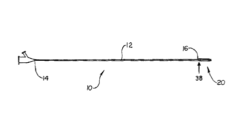
Referring generally to Fig. 1, an embodiment of a stent delivery catheter
10 is shown having a catheter shaft 12 and a catheter tip 20. The catheter
shaft 12 has a
proximal end 14 and a distal end 16. The catheter tip 20 is coupled to the
catheter shaft
distal end 16 at a coupling 38.
The catheter shaft 12 and catheter tip may be made from any suitable
material, such as polyesters and copolymers thereof such as those sold
including
polyalkylene terephthalates such as polyethylene terephthalate (PET) and
polybutylene
terephthalate (PBT) available under the tradename of EKTAR8 available from
Eastman
Chemical Co. in Kingsport, TN, polycyclohexylene terephthalate (PCT);
poly(trimethylene terephthalate) (PTT), PCTG and poly(cyclohexanedimethanol-co-
ethylene terephthalate) (PETG) copolyesters available under the tradename of
EASTARS available from Eastman Chemical Co., PCTA available under the
tradename
CA 02537951 2006-03-03
WO 2005/075014 PCT/US2004/038299
- '6
of DURASTAR available from Eastman Chemical Co., poly(ethylene naphthalate)
(PEN) polyester available from DuPont in Wilmington, DE under the tradename of
TEONEX8; and so forth; polyester elastomers (PEELs); polyamides such as
amorphous
nylon and nylon 12 such as those available from Elf Atochem under the
tradename of
CRISTAMID and copolymers thereof such as GRILAMID TR-55-LX nylon 12
polyether-block-amide available from EMS-American Grilon in Sumter, SC;
polyetherimides available from GE Plastics under the tradename of ULTEMO;
polystyrene and expandable polystyrene (EPS); acrylonitrile-butadiene-styrene
(ABS);
styrene-acrylonitrile (SANs); polyphenylene sulfide (PPS); polyphenylene
oxides
(PPO); interpolymers of PPO and EPS; polyetherketones (PEEK); polyolefins such
as
polyethylenes and polypropylenes including low, medium and high densities such
as
HDPE available under the tradename of ALATHON from Equistar Chemicals;
amorphous polyolefins; polyether-block-amides such as those sold under the
tradename
of PEBAX available from Elf Atochem; polyimides; polyurethanes;
polycarbonates;
polyethers; silicones; as well as any copolymers thereof. The above list is
intended for
illustrative purposes only, and is not intended to limit the scope of the
present invention.
One of ordinary skill in the art has knowledge of such polymeric materials.
The catheter tip 20 may be made from any suitable material, such as
described above, and is desirably more flexible than the catheter shaft 12.
The catheter
tip 20 is desirably made from a soft material, such as Pebax 40D, Pebax 55D or
silicone.
The catheter tip 20 may be attached to the catheter shaft 12 using any
suitable process, such as gluing, heat bonding, RF welding or laser welding.
When
using heat bonding techniques, the catheter shaft 12 and catheter tip 20 are
desirably
made from materials having similar melting temperatures.
Various embodiments of inventive catheter tips 20 are depicted in Figs. 2
¨ 13. Catheter tips 20 desirably comprise an elongate tubular body having a
proximal
end 22, a distal end 24, a lumen 26 extending therethrough, a distal shaft
portion 42 and
a main shaft portion. The main shaft portion may be defined as the portion of
the
catheter tip 20 not defined as the distal shaft portion 42. The main shaft
portion can
have a greater length then the distal shaft portion 42. The catheter tips 20
may
optionally include one or more hub portions 30, one or more markers or marker
portions
32, one or more recessed portions 34, one or more stiffeners or reinforcements
28 and a
CA 02537951 2006-03-03
WO 2005/075014 PCT/US2004/038299
_ 1
radiused tip 36.
A balloon 44 generally includes a proximal waist portion 54 and a distal
waist portion 56. A balloon 44 can be coupled at its proximal waist portion 54
to an
outer catheter shaft 40, and at its distal waist portion 56 to the catheter
tip 20 distal shaft
portion 42. The length of the balloon 44 may be substantially coextensive with
the
catheter tip 20 main shaft portion. The catheter tip 20 may be coupled to the
catheter
shaft distal end 16 near the balloon proximal waist portion 54. In some
embodiments,
the coupling 38 may be proximal to the balloon proximal waist portion 54. In
some
embodiments, the coupling 38 may be distal to the balloon proximal waist
portion 54.
In some embodiments, the catheter tip 20 may include a medical device
mounting region, such as for mounting a stent, and the mounting region can be
distal to -
the coupling between the catheter shaft 12 and catheter tip 20.
Desirably, catheter tips 20 are formed using a molding process or an
extrusion process. Both a molding process and an extrusion process allow the
catheter
tip 20 to be precisely formed having sections of varying diameter. Thus, hub
portions
30, recessed portions 34 and a radiused tip 36 may be integrally formed during
tip
manufacture, without separate installation or grinding steps.
Further, if the catheter tip 20 is formed with an injection molding
process, portions of various embodiments, such as markers 32 or stiffeners 28,
may be
inserted into the mold prior to material injection. Thus, markers 32 and
stiffeners 28
may be insert molded upon the catheter tip 20.
One or more stiffeners 28 may be used to increase rigidity of the catheter
tip, as depicted in Figure 3. A stiffener 28 is desirably insert molded into
the catheter tip
20, and may comprise a strip of material, a cylinder of material, or the like.
In one
embodiment, the stiffener 28 may comprise a cylindrical coil of wire or a
spring. A
stiffener 28 may work to resist kinking of the catheter tip 20.
Markers 32 may comprise radiopaque markers, MR1 markers, and the
like. Markers 32 may be of any suitable shape and desirably comprise
circumferential
bands, as depicted in Figs. 2 and 3. In one embodiment, markers 32 may be
inserted
into the mold during manufacture of the catheter tip 20. As such, material
used to form
the catheter tip 20 forms around the marker 32 during the molding process,
thereby
securing the marker 32 in place without the use of adhesive or a separate
installation
CA 02537951 2011-03-30
8
step. Insert molding additionally allows the markers 32 to have a lower
profile than is
typically achieved with conventional assembly. Desirably, the outer surface of
any
markers 32 may be flush with the outer surface of the catheter tip 20, or even
recessed
beneath the surface.
In some embodiments, the markers 32 may be raised, or otherwise
protrude above the outer surface of the catheter tip 20. The markers 32 may
even
function as hub portions 30.
In some embodiments, the catheter tip 20 may be used in a stent delivery
system, and may be used to deliver inflation expandable, self-expanding or
hybrid
stents. Inflation expandable stents are generally crimped about the delivery
catheter and
the deflated balloon 44. After being maneuvered to the deployment site, the
inflation
expandable stent is expanded to the vessel diameter by fluid inflation of the
balloon 44.
A self-expanding stent is generally formed from a shape-memory material, such
as
Nitinol, and held in a reduced diameter about a catheter with a sheath. Upon
removal of
the sheath, a self-expanding stent will deploy to a deployment diameter. The
delivery
system for a self-expanding stent may or may not use a balloon 44.
Markers 32 are desirably located at a position corresponding to eventual
placement of
end portions of a stent that may eventually be installed about the catheter
tip 20. Thus,
the stent end portions may be adjacent to or otherwise aligned with the
markers 32.
Radiopaque markers 32 may be any suitable material, including barium,
bismuth, tungsten, gold, titanium, iridium, platinum, palladium, silver,
rhenium, alloys
of these materials, and others, such as disclosed in US Patent No. 6,315,790.
MRI
markers 32 may be any suitable material, and desirably a ferro-magnetic,
superparamagnetic or paramagnetic material in such a quantity that the
magnetic field
surrounding the catheter tip 20 is disturbed enough to visualize the marker 32
on a
magnetic resonance imaging system, such as gadolinium, iron or manganese
containing
alloys. Further, the markers 32 may be positioned with a portion raised above
the
surface of the catheter tip 20, and may also be used as a hub to prevent
translocation of
an unexpanded stent.
A molding process is also beneficial in that placement of various features
of the catheter tip 20 is consistent for all tips 20 manufactured from a given
mold. Hub
CA 02537951 2006-03-03
WO 2005/075014 PCT/US2004/038299
_ '9
portions 30, markers 32, stiffeners 28 and recessed portions 34 may be placed
precisely
and consistently in relation to the ends of the catheter tip 20, as well as in
relation to
each other.
Referring to Figs. 4 and 5, hub portions 30 may help to prevent a stent 50
from translocating proximally or distally when the stent 50 is in an
unexpanded state,
such as crimped to the catheter tip 20.
Recessed portions 34 may be located strategically to allow a catheter
assembly to have a lower profile in desired locations. An expansion balloon 44
may
include conical portions 46 where the diameter of the balloon 44 increases or
decreases
rapidly, as best shown in Fig. 5 with the balloon 44 in an expanded
configuration.
When the balloon 44 is installed on a conventional catheter in an uninflated
configuration, the conical portions 46 may bunch undesirably to create a
larger outer
diameter. Recessed portions 34 in the catheter tip 20 may be located to act as
a storage
recess for portions of the balloon, for example the conical portions 46,
thereby allowing
the catheter tip assembly to have a lower profile in those sections.
Further, recessed portions 34 allow for greater flexibility of the catheter
tip 20 in bending about the longitudinal axis. This aids in advancement of the
catheter
through a tortuous anatomy en route to a stent deployment site. However, if a
greater
flexibility is not desired in the regions of recessed portions 34, stiffeners
28 may be used
appropriately for added rigidity.
Additional embodiments of catheter tips 20 may include various
combinations of the features described herein. For example, an embodiment may
include a single hub portion 30, and have no recessed portions 34 and no
markers 32.
Another embodiment may include a single marker 32 and a radiused tip 36.
Referring to Figure 6, an embodiment of a catheter tip 20 is depicted
having a large central recessed portion 34. In this embodiment, the large
recessed
portion 34 may act as a securement recess to help prevent translocation of an
unexpanded stent. The recessed portion 34 also allows for greater flexibility
of the
catheter tip 20 in bending about the longitudinal axis.
A further embodiment, having multiple recessed portions 34 is depicted
in Figure 7. In this configuration, the catheter tip 20 has an undulating or
serpentine
surface along a portion of its length. Multiple recessed portions 34 can be
more
CA 02537951 2006-03-03
WO 2005/075014 PCT/US2004/038299
effective at securing an unexpanded stent than a single, larger recessed
portion.
Multiple recessed portions 34 also allow an increase in longitudinal
flexibility across a
greater length of the catheter tip 20. Adjacent recessed portions 34 may have
varying
outer diameters. Further, portions of the catheter tip 20 between adjacent
recessed
5 portions 34 may function as securement hubs 30, and may have a greater
outer diameter
than the tip proximal end 22 or the tip distal end 24.
Figure 8 shows an embodiment wherein the catheter tip 20 includes a
large recessed portion 34b. In this configuration, a stent 50 may be mounted
upon the
tip 20 such that the outer surface of the stent 50 may be flush with the tip
20 outer
10 diameter, or even recessed beneath the tip 20 outer diameter. Markers 28
are further
recessed within the large recessed portion 34b, and thus may be located
proximal to
ends of the stent 50. Further, portions of the catheter tip 20 that are
directly adjacent to
the ends of the stent 50 can act as securement hubs 30 and prevent the stent
50 from
translocating.
Figure 9 depicts another embodiment of a catheter tip 20, wherein
securement hubs 30 are located outwardly from the markers 28. In this
embodiment, a
stent 50 may be mounted upon the tip 20 such that the outer surface of the
stent 50 may
be flush with the securement hubs 30, or nested between the securement hubs
30.
Markers 28 may be located proximal to the ends of the stent 50.
In another embodiment, the catheter tip 20 may be formed having various
regions, each region having properties that may be different from the other
regions of
the tip 20. For example, a region may comprise a marker region, and thus have
radiopaque or magnetic properties. A region may also be more or less flexible
than an
adjacent region. Various regions may have differing melting points, and a
catheter tip
20 may be molded utilizing a multiple step process wherein a first material
composition
is injected into a first mold to form a portion of the tip, which can then be
inserted into a
second mold, and a second material composition may be injected. Properties of
regions
may be adjusted via the use of various materials in forming the regions of the
catheter
tip 20. Thus, a catheter tip 20 manufactured to have marker regions may have
radiopaque material entrained with the polymer material for that region, and
would not
require a separate radiopaque marker 32 in order to be viewable under
fluoroscopy.
Figure 10 shows a catheter tip 20 comprising a first region 60, one or
CA 02537951 2011-03-30
11
more second regions 62, and one or more marker regions 64. The first region 60
may
comprise a soft distal region. A first region 60 may be made from a first
matrix material
composition. A second region 62 may have reduced flexibility as compared to a
first
region 60. A second region may be made from a second matrix material
composition.
A first matrix material composition may include portions of materials that are
also
present in a second matrix material composition. A reduced flexibility may be
accomplished, for example, by including stiffening fibers within the polymer
used to
form the second region 62. Stiffening fibers can include carbon fibers,
polypropylene
fibers, polyolefin fibers, or any other material to accomplish an appropriate
reduction in
flexibility.
A marker region 64 can be visible under fluoroscopy or MRI. A
radiopaque region may be formed by including radiopaque material in the
region. For
example, up to 90% bismuthoxide by weight may be loaded into the polymer
matrix.
Other materials include ceramic materials such as tungsten carbide, tungsten
boride, and
the like, and metals such as platinum, tantalum, iridium, tungsten, rhenium
gold and
alloys of such metals. An MRI region may be similarly formed using any
appropriate
material, such as terbiumoxide, gadoliniumoxide and dysrosiumoxide.
Regions of the catheter tip 20 may be formed using any suitable methods,
such as molding or extrusion. For example, each region may be injection
molded, and
each region may be formed with an individual injector. Methods of forming an
extrusion having alternating materials are disclosed in US 5622665.
Catheter tips 20 having regions of varying stiffness and marker regions
may also include all of the features of inventive catheter tips 20 described
herein, such
as recessed portions 34, securement hubs 30, markers 32 and stiffeners 28. In
some
embodiments, marker regions 64 may include a raised portion and function as a
securement hub 30. In some embodiments, the entire stent mounting region may
comprise a marker region 64. Further, a region may comprise both a marker
region 64
and a region of reduced flexibility.
In another embodiment, portions of the catheter tip 20 may have various
cross-sectional shapes. Figures 11 and 12 depict a catheter tip 20 having a
triangular
cross-sectional portion. In some embodiments, a varying cross-sectional shape
portion
CA 02537951 2006-03-03
WO 2005/075014 PCT/US2004/038299
12
can be formed wherein the cross-sectional shape has a reduced cross-sectional
area
when compared to the catheter shaft 12. Areas where a cross-sectional shape
does not
extend to the catheter shaft 12 diameter may be described as reduced profile
zones. In
other embodiments, cross-sectional area of a shaped portion may be greater
than that of
the catheter shaft 12.
A shaped cross-sectional portion may be better suited to receive an
unexpanded balloon than a circular cross section. In some embodiments, the
folds of an
unexpanded balloon may be located in a reduced profile zone, and as such, the
balloon
may have a lower cross-sectional profile than that of the catheter shaft 12.
A shaped cross-sectional portion may be of any shape desired. Various
embodiments include a square, pentagon, hexagon, and the like. The number of
sides of
the shape may increase until the shape becomes substantially circular.
A catheter tip 20 having a shaped cross-sectional portion may also have
circular portions which are of the same dimensions as the catheter shaft 12.
As depicted
in Figure 11, the catheter tip 20 proximal end 22 is of the same shape as the
catheter
shaft 12.
Catheter tips 20 that include a shaped cross-sectional portion may also
include all of the features of inventive catheter tips 20 described herein,
such as regions
of varying stiffness and marker regions, recessed portions 34, securement hubs
30,
markers 32 and stiffeners 28.
In another embodiment, a catheter tip 20 may be separate from a catheter
shaft 12. A separate catheter tip 20 can later be coupled to a catheter shaft
12. Figure
13 shows a separate catheter tip 20. A catheter tip 20 may have a first free
end 66 and a
second free end 68. The catheter tip 20 may have a longitudinal axis, a length
along the
longitudinal axis, a width orthogonal to the length, and a height orthogonal
to both the
length and the width. The catheter tip 20 length can encompass a range to be
suitable
for delivery of a range of medical devices. For example, the catheter tip 20
may have a
length of 4 millimeters in some embodiments, and a length of 70 millimeters in
some
other embodiments. The length of the catheter tip 20 can also vary in relation
to the
width or diameter. The length can be 4 times the width or diameter in some
embodiments, and 70 times the width or diameter in some other embodiments.
Many
other specific lengths may be utilized according to the particular
application. The
CA 02537951 2011-03-30
=
13
catheter tip 20 can include a balloon 44. The main shaft portion of the
catheter tip 20
can be substantially coextensive with the balloon 44.
The above disclosure is intended to be illustrative and not exhaustive.
This description will suggest many variations and alternatives to one of
ordinary skill in
this art. All these alternatives and variations are intended to be included
within the
scope of the claims where the term "comprising" means "including, but not
limited to".
Those familiar with the art may recognize other equivalents to the specific
embodiments
described herein which equivalents are also intended to be encompassed by the
claims.
Further, the particular features presented in the dependent claims can be
combined with each other in other manners within the scope of the invention
such that
the invention should be recognized as also specifically directed to other
embodiments
having any other possible combination of the features of the dependent claims.
For
instance, for purposes of claim publication, any dependent claim which follows
should
be taken as alternatively written in a multiple dependent form from all prior
claims
which possess all antecedents referenced in such dependent claim if such
multiple
dependent format is an accepted format within the jurisdiction (e.g. each
claim
depending directly from claim 1 should be alternatively taken as depending
from all
previous claims). In jurisdictions where multiple dependent claim formats are
restricted, the following dependent claims should each be also taken as
alternatively
written in each singly dependent claim format which creates a dependency from
a prior
antecedent-possessing claim other than the specific claim listed in such
dependent claim
below.
This completes the description of various embodiments of the invention.
Those skilled in the art may recognize other equivalents to the specific
embodiment
described herein which equivalents are intended to be encompassed by the
claims
attached hereto.