Note: Descriptions are shown in the official language in which they were submitted.
CA 02537969 2006-03-07
WO 2005/023430 PCT/GB2004/003871
1
WASTE SOLID CLEANING
FIELD OF THE INVENTION
This invention relates to a method and apparatus for
removing oil from oil-contaminated waste. In particular,
the present invention relates to the removal of oil from
drilling wastes such as drill cuttings and oil slops, and
other industrial oily wastes such as refinery and
interceptor wastes by forming a microemulsion of reduced
particle size oil-contaminated material.
BACKGROUND OF THE INVENTION
Drilling fluids or "muds" are oil- or water-based
formulations which are used as lubricants and stabilisers
in the drilling of oil and gas wells. Oil-based muds
tend to have superior performance and are used in
difficult drilling conditions, such as in horizontal
drilling.
Drilling mud is pumped down hole to a drill bit and
provides lubrication to the drill string and the drilling
bit. The mud also prevents or inhibits corrosion and can
be used to control the flow of fluid from a producing
formation.
Drilling mud returning to surface may carry with it
rock cuttings which are commonly known as 'drill
cuttings'. The drill cuttings may be saturated with oil.
Depending on the .character of the rock formation being
drilled, the dril°1 cuttings may comprise, for example,
clay, shale, sandstone or limestone. The returning mud
with entrained drill cuttings is separated into drilling
mud and cutting fractions by passing the returning mud
over, for example, shaker screens or other separating
equipment. The separated mud may be reused, while the
CONFIRMATION COPY
CA 02537969 2006-03-07
WO 2005/023430 PCT/GB2004/003871
2
oil-contaminated cutting fractions are stored for
subsequent treatment and disposal.
Disposal of oil-contaminated drill cuttings is a
major problem in the oil industry. The drill cuttings
may contain up to 250 oil by weight. Although it was
previous practice to dispose of untreated cuttings simply
by dumping the cuttings adjacent the drill site, for
example, onto the seabed, this is environmentally
unfriendly and is now illegal in many jurisdictions.
There is currently legislation pending, or in place, in
many countries which only permits "zero discharge"
drilling operations. Dumping of untreated cuttings is
therefore becoming prohibited.
Currently, in offshore operations, it is practice to
collect and store the oil-contaminated drill cuttings on
an offshore drilling unit and thereafter transport the
drill cuttings to an onshore location for treatment and
cleaning. Alternatively, in some cases the drill
cuttings can be slurrified and re-injected into a sub sea
formation. However, this again has its own environmental
problems.
With thousands of tonnes of drill cuttings being
formed in drilling operations worldwide, the
transportation costs are significant. For example,
currently there are approximately 350 wells that are
drilled in the North Sea every year and each produces an
average of 800 - 1,000 tonnes of waste drilled cuttings.
Accordingly, it can be estimated that X80,000 - 300,000
tonnes of waste drilled cuttings are produced each year
and around 50,000 tonnes of drill cuttings are brought
onshore each year for treatment.
The contaminated drill cuttings are treated onshore
using conventional means to remove as much oil as
possible and thereafter are, for example, sent for
CA 02537969 2006-03-07
WO 2005/023430 PCT/GB2004/003871
3
landfill. The treated cuttings may also be utilised as
road building material, low grade building products or as
fertiliser filler.
The storing of oil-contaminated drill cuttings and
well bore clean-up fluids on a drilling platform is a
major problem due to limited storage space. For example,
a single drilling operation may produce up to 800 tonnes
of drilling waste and 100 tonnes of pit and well-bore
clean-up fluid which is typically stored in 5 tonne
capacity containers or skips and thereafter transferred
offshore. Many containers or skips are therefore
required which takes up valuable deck space.
Furthermore, if bad weather prevents transport vessels
from emptying the full containers or skips, drilling
operations may have to be suspended until the weather
improves and the material can be transported.
The current practice of storing oil-contaminated
drill cuttings in containers or skips on the oil platform
also leads to health and safety issues. For example, the
loading of containers or skips onto a transport vessel is
usually done by crane. This is a slow process and
requires many crane movements (up to 1,000 additional
movements for every well), thereby increasing the risk of
accidents occurring.
An alternative approach to storing the oil-
contaminated drill cuttings in containers or skips is to
slurify the drill cuttings and store them on or below the
deck of the drilling platform or vessel. The macerated
cuttings are subsequently pumped onto a transport vessel.
However, such slurified cuttings are generally too fine
to be handled easily in conventional onshore drill
cutting processing facilities. Furthermore, while the
macerated drill cuttings are stored on the platform, the
drill cuttings must be maintained in circulation to avoid
CA 02537969 2006-03-07
WO 2005/023430 PCT/GB2004/003871
4
settling-out of the cuttings; any settling of the
cuttings would prevent pumping onto a transport vessel.
Such a process also has the disadvantage of increasing
the volume of the waste.
Consequently, all of the known approaches to safely
disposing of oil-contaminated drill cuttings are heavily
dependent on weather conditions to permit transport
vessels to approach the offshore facility and offload the
oil-contaminated material such as drill cuttings. In
some areas, for example, the eastern Atlantic Ocean to
the west of the Shetland Isles, it has been estimated
that in winter some 650 of drilling costs are weather
related. Reduction of the reliance on favourable weather
conditions would therefore be of considerable benefit.
Similarly, in other industries such as refining and
waste management, there are large quantities of oily
solids, such as interceptor sludges and the like that
require disposal. Landfill is no longer an alternative
for liquid wastes, due to new landfill legislation, and
as a result these substances require treatment to provide
recyclable/inert materials than can be disposed of in an
environmentally safe manner. Current methods require
transportation and typically treatment by thermal
desorbtion, incineration or mixing with inert materials
(such as with fly ash) and landfill. New legislation is
also prohibiting the mixing of hot waste material with
fly ash. This is ,expensive from both a financial and an
environmental aspect.
Techniques such as described in WO 98/05392, WO
00/54868, WO 02/20473, GB 0305498.8, GB 0306628.9, GB
0307288.1 and GB 2347682B, incorporated herein by
reference, are known to remove oil from oil-contaminated
wastes such as drill cuttings. The material obtained
using these processes may not have a low enough oil
CA 02537969 2006-03-07
WO 2005/023430 PCT/GB2004/003871
content to be disposed of overboard on an oil platform
and may have to undergo a series of treatment cycles or
more than likely still require transportation to an
onshore treatment facility. In addition, the sample sizes
5 used in these patents is only about 60g and is therefore
not a realistic measure for treating large scale volumes.
A further significant problem is the actual
percentage of oil content discussed in the prior art such
as in GB 2347682B. In GB 2347682B a retort method is
used to obtain the oil content values. Retort methods
are inherently inaccurate and produce an error of at
least plus/minus 2.5% in measured oil content.
Furthermore, in GB 2347682B the initial oil content is 70
which is a low initial value to start off with. For
example, cuttings coming off a shaker screen usually have
about 15 - 220 oil content. The shale cuttings in GB
2347682B would therefore appear to have undergone some
initial treatment or natural evaporation prior to adding
a surfactant. It is therefore extremely unlikely that
the process in GB 2347682B could cope with cuttings
containing 15 - 220 oil content. Additionally, in GB
2347682B a polycarbonate centrifuge bottle is used which
may further distort the results as the polycarbonate will
potentially absorb some oil.
The method disclosed in GB 2347682B is therefore
highly unlikely to produce repeatable results when
treating drill cuttings or oil slops to provide resulting
solid material which has an oil content of less than 10.
The oil content must also be measured using accurate
measurement devices such as Gas Chromatography (GC) or
Fourier Transform Infrared Spectroscopy (FTIR) otherwise
anomalous results are obtained.
CA 02537969 2006-03-07
WO 2005/023430 PCT/GB2004/003871
6
It is amongst the objects of the present invention
to obviate or mitigate at least one of the aforementioned
problems.
It is a further object of the present invention to
provide a method of removing oil from oil-contaminated
wastes.
It is a yet further object of a preferred embodiment
of the present invention to remove oil from oil-
contaminated drilling waste such as drill cuttings to a
level below 1o so that the treated drill cuttings may be
disposed of overboard from an offshore drilling platform
or vessel.
SUMMARY OF THE INVENTION
According to a first aspect of the present invention
there is provided a method for removing oil from oil-
contaminated material the method comprising the steps of:
a) mixing oil-contaminated material with an
average particle size of less than about 2000
microns with a water-based solution of a
surfactant to form an oil-in-water
microemulsion containing a substantially oil-
free solid material; and
b) separating the oil-in-water microemulsion from
the substantially oil-free solid material.
The oil-contaminated material may, for example, be
any drilling waste such drill cuttings or oil slops
formed during drilling for oil or gas. The drill
cuttings may be saturated with oil and may comprise up to
250 oil by weight. Alternatively, the oil-contaminated
material may, for example, be oil-contaminated material
formed in refineries or during waste management such as
interceptor sludges.
CA 02537969 2006-03-07
WO 2005/023430 PCT/GB2004/003871
7
The substantially oil-free solid material may have
less than 10 oil by weight, less than 0.50 oil by weight
and preferably less than 0.1o oil by weight. The term oil
herein is taken to mean any hydrocarbon compound.
Typically, the oil-contaminated material may have an
average particle size of less than about 1000 microns,
less than about 500 microns or preferably less than about
100 microns, less than about 10 microns or less than
about 1 micron. The particles may also have a range of
about 0 - 1000 microns, about 0 - 500 microns, about 0 -
200 microns or about 0 - 50 microns. It has been found
that it is preferred to reduce the particles down to less
than about 130 microns.
During or prior to mixing with the water-based
solution of the surfactant, the particles forming the
oil-contaminated material may be reduced in size. This
reduction in particle size may be done by any mechanical,
physical, fluidic or ultrasonic means.
The particles may be reduced in size by, for
example, any type of shearing means. By shearing is meant
that the particles are cut open thereby reducing the
particle sizes and increasing the available surface area.
The shearing means may, for example, be rotatable cutting
blades . The cutting blades may be rotated at high speeds
of up to about 1000 - 6000 rpm. The shearing process may
last for about, for example, 2 - 30 minutes or preferably
about 5 - 10 minutes.
The shearing means may comprise a plurality of
impellors mounted on a single drive shaft. Preferably,
there may be two impellors. Typically, the impellors
comprise a series of blades. Conveniently, the pitch of
the blades in the impellors may be substantially opposite
or at least substantially different so that the blades
cause the particles to impact and collide with each
CA 02537969 2006-03-07
WO 2005/023430 PCT/GB2004/003871
8
other. By causing the particles to impact against each
other, leads to a high shearing effect that reduces the
particle sizes and increases the surface area of the
particles. As the particles shear themselves, rather than
the actual blades, this reduces wear and tear on the
impellor blades. In this embodiment, the impellors may
rotate at a reduced speed of about 300 - 2000 rpm. The
impellors may be separated by any suitable distance.
Preferably, the impellors may be separated by a distance
of about half the diameter of the rotating impellors such
as, for example, about 0.2m to 0.5m.
An alternative shearing means may comprise a rotor
which may be enclosed within a casing such as, for
example, a substantially cylindrical casing. The oil-
contaminated material may initially be drawn in through
an opening in the casing on rotation of the rotor. On
rotation of the rotor, the particles may be forced via
centrifugal force to the outer regions of the casing
where the particles may be subjected to a shearing
action.
The particles may shear against each other. The
shearing action may occur in a precision machined
clearance of about 100 - 1000 microns or preferably about
50 - 200 microns between the ends of the rotor and the
inner wall of the casing. The milled particles will then
undergo an intense hydraulic shear by being forced, at
high velocity, out through perforations in the outer wall
of the casing. During this process, fresh material may
be drawn into the casing. Using this process, the
particles may be reduced down to a size of about 0 - 500
microns or preferably about 0 - 180 microns. By reducing
the particle sizes, the surface area of the oil-
contaminated material is increased which facilitates the
ability of the surfactant to remove oil deposits
CA 02537969 2006-03-07
WO 2005/023430 PCT/GB2004/003871
9
entrapped in the oil-contaminated material. To aid the
shearing process, water may be added to the oil-
contaminated material which, in effect, turns the
material into a slurry.
Alternatively, grinding means may be used to reduce
the sizes of the particles forming the oil-contaminated
material.
In a yet further alternative, an ultrasonic process
using high frequency electromagnetic waves may be.used to
reduce the particle sizes; the particles disintegrate on
exposure to the high frequency electromagnetic waves.
A further alternative to reduce the particle sizes
may be to use a fluidic mixer such as an air driven
diffuser mixer which uses compressed air to suck the
particles through a mixer. A suitable fluidic mixer is
manufactured by Stem Drive Limited and is described, for
example, in WO 00/71235, GB 2313410 and GB 2242370 which
are incorporated herein by reference. In WO 00/71235, a
fluidic mixing system is described wherein at least one
pneumatic mixer may be arranged to eject gas at an angle
to the vertical to thereby entrain a flow of fluid
material within a tank to cause mixing and a reduction in
particle sizes of a fluid material. WO 00/71235 also
describes a fluid powered mixer wherein 'gas from a gas
supply is ejected from a perforated annulus and the
forward flowing gas pulls material from the rear of the
mixer. Mixed material of reduced particle size may then
be forcibly ejected from the mixer.
Another alternative is to use a cavitation high
shear mixer wherein a vortex is used to create greater
turbulence to facilitate the reduction in particle sizes.
Such a device is made by Greaves Limited and is described
as the Greaves GM Range (Trade Mark). The Greaves GM
Range (Trade Mark) of mixers uses fixed vertical baffles
CA 02537969 2006-03-07
WO 2005/023430 PCT/GB2004/003871
to create extra turbulence when, for example, a deflector
plate is lowered.
A further alternative is to use a hydrocyclone
apparatus or any other suitable centrifugation system.
5 The shearing method may comprise any combination of
the alcove-described methods.
Prior to the addition of any surfactant, an electric
current may be passed through the oil-contaminated
material. This does not affect the particle size but
10 merely helps to separate out the oil. It has been found
that by using a burst cell electro-chemical system and by
customising the wave shape, frequency and pulse, the oil-
contaminated material may be separated into, for example,
3 phases : an oil phase, a water phase and a solid phase .
A centrifugation process may be used to separate the
different phases. Alternatively, material may be left
overnight for the separation to occur. 'This process
reduces the amount of oil in the solids thereby reducing
the amount of oil which needs to be removed by the
surfactant. This may reduce the amount of surfactant
which may be required to remove the oil. This is
advantageous as the surfactant is expensive.
To remove oil deposits from the oil-contaminated
material, the surfactant may be added to the oil
contaminated material during the step of reducing the
particle sizes. Typically, the surfactant may be capable
of spontaneously absorbing oil, forming an oil-in-water
microemulsion. An oil-in-water microemulsion may be
defined, although not wishing to be bound by theory, as a
thermodynamically stable, single-phase mixture of oil,
water and surfactant, such that the continuous phase is
water (which may contain dissolved salts) and the
dispersed phase consists of a monodispersion of oil
droplets, each coated with a close-packed monolayer of
CA 02537969 2006-03-07
WO 2005/023430 PCT/GB2004/003871
11
surfactant molecules. The inherent thermodynamic
stability arises from the fact that, due to the presence
of the surfactant monolayer, there is no direct oil-water
contact.
In the oil-in-water microemulsion environment, the
oil is effectively encapsulated within a surfactant
shell,, and is no longer in direct contact with the
original solid material.
Typically, the oil-contaminated material and
surfactant may be mixed with an excess amount of water.
The water may comprise a salt such as NaCl.
By mixing the oil-contaminated material with the
surfactant this may form a range of systems known as
Winsor Type I - IV systems. However, it should be noted
that the present application is not limited to any of the
Winsor systems. In addition, the Winsor system during
the procedure may change. For example, Winsor Type II and
Type IV systems may be used.
In particular, by mixing the oil-contaminated
material with the surfactant in an excess amount of water
(i.e. the water forms the substantial part of the
mixture), a two-phase system may be formed comprising: an
upper oil=containing microemulsion phase (containing
substantially all of the oil, substantially all of the
surfactant and some water) and a lower water phase
(containing most of the water and salt, if any). This is
known as a Winsor Type II system. The upper oil
containing microemulsion phase consists of a
monodispersion of oil droplets, each coated with. a close
packed monolayer of surfactant molecules.
Microemulsions by definition are thermodynamically
stable. This means that for a particular composition
(i.e. type and amount of each component), and a
particular temperature, a single microemulsion phase is
CA 02537969 2006-03-07
WO 2005/023430 PCT/GB2004/003871
12
preferred over a system of separate phases of oil, water
and surfactant. Microemulsions form spontaneously when
their constituents are mixed together. However, the oil
may be 'flipped' out of the microemulsion using a salt
such as CaCl2 or NaCl.
In contrast, normal emulsions are not
thermodynamically stable. Emulsions form only by input
of mechanical energy (e.g. by shaking or sonication) and
the emulsion system can only be maintained by continuous
input of energy. When this input of energy is withdrawn,
the emulsion phase separates providing distinct oil and
water phases.
A specific property relevant to the microemulsions
of the present invention is that the interfacial surface
tension generated between a microemulsion phase and a
polar phase (e.g. water, air or a solid material such as
clay) is extremely low. Sodium chloride may also be added
to thermodynamically force the oil out of the water
whereupon the oil may be skimmed from the top of the
water. Although not wishing to be bound by theory it is
thought that on formation of the microemulsion, the
interfacial surface tension between an upper oil
containing microemulsion phase and a lower water phase is
extremely low allowing complete separation of the two
phases.
Typically, any microemulsion forming surfactant
which is capable of effectively trapping oil within a
surfactant shell is suitable for the present invention.
The surfactant may also be mixed with a salt such as
sodium chloride which may improve the extraction of the
oil. Mixtures of different surfactants may also be used.
The surfactant may be selected from suitable
cationic, anionic or nonionic surfactants commercially
available. Biosurfactants may also be used.
CA 02537969 2006-03-07
WO 2005/023430 PCT/GB2004/003871
13
In particular, the surfactant may be selected from
any of the following: sodium bis-2-ethylhexyl
sulphosuccinate, sodium dodecyl sulphate,
didodecyldimethyl ammonium bromide, trioctyl ammonium
chloride, hexadecyltrimethylammonium bromide,
polyoxyethylene ethers of aliphatic alcohols,
polyoxyethylene ethers of 4-t-octylphenol, and
polyoxytheylene esters of sorbitol. Typical
polyoxyethylene ethers may, for example, be Brij 56
(Trade Mark) and Brij 96 (Trade Mark). Typical
polyoxyethylene ethers of 4-t-octylphenol may, for
example, be Triton X-100 (Trade Mark). A suitable
polyoxyethylene ester of sorbitol may, for example, be
Tween 85 (Trade Mark). A combination of different
surfactants may also be used.
The surfactant according to the following general
Formula I may be used:
BONa
SS
(CH2) \0/I ~ \O
O
wherein
R~ - -H or -CH3
2 5 R~ -
H OH
CH CH
3( 2)n1
where n1 may take any value as long as, n1 < n
3 0 R1 - R2 -
~~ H
CH3(CH2)ni--'-'C \
CA 02537969 2006-03-07
WO 2005/023430 PCT/GB2004/003871
14
10
where n1 may take any value as long as n1 < n, or
R1 = -H or -CH3
Rz =
H
~OH
CH3(CH2)m UH2)n2 C\
where n1 and n2 may take any value, as long as (n1 +
n2 ) < n, or
Ri - R2 =
H
~ ~ON
CH3(CH2)ni (CH2)n2 CC
where n1 and n2 may take any value, as long as (n1 +
n2) < n.
The formed oil-in-water microemulsion phase and the
water phase may be separated from the treated
substantially oil-free solid material by any physical
means such as filtration and/or centrifugation (e. g.
hydrocyclones/decanter centrifuge).
The treated, substantially oil-free solid material
may then undergo a series of rinsing steps to remove any
remaining oil-in-water microemulsion and any remaining
oil entrapped within the drill cuttings. Water or salt
water may be used in the rinsing step. A further
filtration and/or centrifugation process may be used to
separate the substantially oil-free solid material from
any liquid material used in the rinsing process.
The obtained solid material may be tested to ensure
that the amount of oil has been reduced to an acceptable
CA 02537969 2006-03-07
WO 2005/023430 PCT/GB2004/003871
level such as below 10 oil by weight, below 0.50 oil by
weight or preferably below 0.10 oil by weight. If the
oil level is too high, the material may be retreated.
Solid material which has less than 1% oil by weight
5 may be discarded overboard from an oil platform or vessel
onto the seabed. The solid material is measured as a dry
material i.e. not wet.
Conveniently, the oil in the oil-in-water
microemulsion may be recovered by temperature-induced
10 phase separation using well-known procedures.
According to a second aspect of the present
invention there is provided a method for removing oil
from oil-contaminated material comprising the steps of:
a) reducing the particle size of oil-contaminated
15 material;
b) mixing the reduced particle size material with
a water-based solution of a surfactant to form
an oil-in-water microemulsion containing a
substantially oil-free solid material; and
c) separating the oil-in-water microemulsion from
the substantially oil-free solid material.
According to a third aspect of the present invention
there is provided apparatus for removing oil from oil-
contaminated material comprising:
a) means for mixing oil-contaminated material with
an average particle size of less than about
2000 microns with a water-based solution of a
surfactant to form an oil-in-water
microemulsion containing a substantially oil
free solid material; and
b) means for separating the oil-in-water
microemulsion and the substantially oil-free
solid material.
CA 02537969 2006-03-07
WO 2005/023430 PCT/GB2004/003871
16
The apparatus may also comprise means for reducing
the particle size of the oil-contaminated material. Any
form of mechanical, physical, fluidic or ultrasonic means
may be used to reduce the particle sizes.
The apparatus may be portable and adapted to be
situated on, for example, an oil or gas drilling platform
or vessel. The apparatus may be self-contained or
containerised.
The means for reducing the particle sizes may
comprise shearing means. The shearing means may comprise
rotatable cutting blades. The cutting blades may be
rotated at high speeds of up to about 1000 - 6000 rpm.
The cutting blades shear the particles of the oil-
contaminated material.
Typically, the shearing means may comprise a
plurality of impellers mounted on a single drive shaft.
The impellers may comprise a series of blades.
Conveniently, the pitch of the blades in each of the
impellers may be substantially opposite or at least
substantially different so that the impellers may cause
the particles to impact onto each other. By causing the
particles to impact, against each other, leads to a
shearing effect which reduces the particle sizes and
increases the surface area of the particles. The
impellers may rotate at a speed of about 300 - 2000 rpm.
The impellers may be separated by any suitable distance.
Preferably, the impellers may be separated by a distance
of about half the diameter of the rotating impellers such
as, for example, about 0.2 to about 0.5 m.
In an alternative, the shearing means may comprise a
rotor which may be enclosed within a casing such as
substantially cylindrical casing. The oil-contaminated
material may initially be sucked in through an opening in
the casing on rotation of the rotor. On rotation of the
CA 02537969 2006-03-07
WO 2005/023430 PCT/GB2004/003871
17
rotor, the particles may be forced via a centrifugal to
the outer regions of the casing where they may be
subjected to a milling action. The milling action may
occur in a precision machined clearance of about 50 - 500
microns or preferably about 70 - 180 microns between the
ends of the rotor and the inner wall of the casing. The
milled particles will then undergo an intense hydraulic
shear by being forced, at high velocity, out through
perforations in the outer wall of the casing. During
this process, fresh material may be drawn into the
casing. Using this process, the particles may be reduced
down to a size of about 0 - 500 microns or preferably
about 0 -180 microns.
Alternatively, the means for reducing the particle
sizes may be grinding means for grinding the particles
into finer particles.
In a further alternative, the means for reducing the
particle sizes may comprise ultrasonic means.
In a yet further alternative, a fluidic mixer or a
cavitation high shear mixer may be used to reduce the
particle sizes.
Alternatively any combination of the above methods
may be used to reduce the particle sizes.
Any means suitable for mixing the oil-contaminated
material and the surfactant may be used. For example,
cutting blades on rotation may cause mixing to occur or a
separate stirrer may be incorporated into the apparatus.
The apparatus may also be agitated by, for example,
shaking or inverting to mix the different components.
Typically, a filtration and/or centrifugation unit
may be used to separate the formed oil-in-water
microemulsion from the treated, substantially oil-free
solids. However, any other suitable separating means may
be used. In a further alternative, a combination of
CA 02537969 2006-03-07
WO 2005/023430 PCT/GB2004/003871
18
shakers and hydrocyclones' and may be used such as the
ES1400 microfluidic system manufactured by Triflow
Industries.
The apparatus may comprise a series of rinsing
areas, for example tanks, wherein the substantially oil
free solid material may be rinsed with, for example,
water or salt water to remove any retained oil-in-water
microemulsion and oil. The substantially oil-free solid
material may be separated using a filter or a
centrifugation unit.
The apparatus may also comprise a fluid treatment
system which treats the fluid removed from the system
which will be contaminated with oil. The fluid treatment
system may comprise a plurality of adsorbing cartridges
which adsorb oil. This process may be continued until
the water has less than 40 ppm total hydrocarbon content
and may be discharged safely into the sea. The oil
adsorbing cartridges may be made from any suitable oil
adsorbing material such as polycarbonate. Alternatively,
oil absorbing cartridges may be used.
According to a fourth aspect of the present
invention there is provided apparatus for removing oil
from oil-contaminated material comprising:
a) means for reducing the particle size of oil-
contaminated material;
b) means for mixing the reduced particle size
material with a water-based solution of a
surfactant to form an oil-in-water
microemulsion containing a substantially oil
free solid material; and
c) means for separating the oil-in-water
microemulsion and the substantially oil-free
solid material.
CA 02537969 2006-03-07
WO 2005/023430 PCT/GB2004/003871
19
According to a fifth aspect of the present
invention, there is provided a method of removing oil
from oil-contaminated material using a method according
to the first aspect and receiving payment for use of such
method.
According to a sixth aspect of the present
invention, there is provided apparatus for removing oil
from oil-contaminated material according to the third
aspect and receiving payment for rental of said apparatus
and/or selling a surfactant.
BRIEF DESCRIPTION OF THE DRATnIINGS
Embodiments of the present invention will now be
described, by way of example only, with reference to the
accompanying drawings in which:
Figure 1 is a flow chart representing steps in a
method of removing oil from drill cuttings according to
an embodiment of the present invention;
Figure 2 is a schematic representation of apparatus
used to reduce the particle sizes of drill cuttings
according to a further embodiment of the present
invention;
Figure 3 is a schematic representation of apparatus
used to reduce the particle sizes of drill cuttings
according to a yet further embodiment of the present
invention;
Figures 4a~and 4b represent a blending impellor and
a shear rotor according to further embodiments of the
present invention;
Figures 5a - 5c are schematic representations of
apparatus used to reduce the particle sizes of drill
cuttings according to a further embodiment of the present
invention;
CA 02537969 2006-03-07
WO 2005/023430 PCT/GB2004/003871
Figure 6 is a schematic representation of apparatus
used to reduce the particle sizes of oil contaminated
material and remove the oil from the material according
to a yet further embodiment of the present invention;
5 Figure 7 is a side view of the apparatus shown in
Figure 6;
Figure 8 is a top view of the apparatus shown in
Figures 6 and 7;.
Figure 9 is an end view of the apparatus shown in
10 Figures 6 - 8;
Figure 10 is a side view of a water treatment system
according to a further embodiment of the present
invention;
Figure 11 is a top view of the water treatment
15 system shown in Figure 10;
Figure 12 is a part sectional view of part of the
water treatment system shown in Figures 10 and 11;
Figures 13 and 14 are flow charts representing steps
in a method of removing oil from raw slops according to
20 an embodiment of the present invention; and
Figures 15 and 16 are flow charts representing steps
in a method of removing oil from drill cuttings according
to an embodiment of the present invention.
DETAILED DESCRIPTION
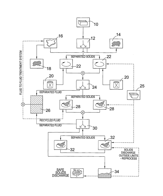
Figure 1 is a flow chart of steps in a process of
removing oil from solids such as drill cuttings.
Although the following description relates to the
treating of oil-contaminated drill cuttings, any other
oil-contaminated solid material may be treated in a
similar way.
Drilling mud which is circulated downhole becomes
mixed with drill cuttings. The resulting mixture,
identified by the reference numeral 10 in Figure 1,
CA 02537969 2006-03-07
WO 2005/023430 PCT/GB2004/003871
21
comprises drilling mud and oil-contaminated drill
cuttings.
The mixture 10 is initially passed through a
separator 12 which separates the mixture 10 into drilling
mud and separated solids. The drilling mud is recycled
to the drilling system.
The separated drill cuttings are then mixed with a
surfactant 20 (i.e. a 'mixing agent') in a mixing
apparatus 22. Water or salt water is added from a water
. tank 25 to form a slurry. As shown in Figure 1, there is
a number of mixing apparatus 22.
Figure 2 is a schematic representation of possible
mixing apparatus 22.. The mixing apparatus 22 comprises a
container 110 and a cavitation mixer, generally
designated 112, comprising rotatable blades 114 on a
drive shaft 116. The rotatable blades 114 are enclosed
in a casing 119 which has a plurality of apertures (not
shown). The cavitation mixer 112 also comprises a series
of baffles 118 and a deflector plate 120. The baffles
118, deflector plate 120 and plurality of apertures in
the casing 119 serve to increase turbulence during
stirring and improves the shearing process. The height
of the deflector plate 120 may be adjusted to maximise
the cavitation. The drive shaft 116 is connected to a
motor 117 and rotates at about 1000 - 6000 rpm for about
5- - 10 minutes.
The cavitation mixer 112 shears the drill cuttings
and reduces the particle sues of the drill cuttings.
Shearing the drill cuttings has the advantageous effect
of increasing the surface area of the drill cuttings.
The particles are reduced in size from about 0 - 1000
microns to about 0 - 100 microns. Increasing the surface
area facilitates the access of the surfactant to oil
deposits entrapped within the drill cuttings.
CA 02537969 2006-03-07
WO 2005/023430 PCT/GB2004/003871
22
The surfactants used are capable of spontaneously
absorbing oil forming so-called oil-in-water
microemulsions.
After mixing for about 10 minutes, the resulting
mixture is passed to a centrifugation unit 24 which
separates the drill cutting particles from the formed
oil-in-water microemulsion and ' water phase. The
centrifugation procedure lasts for about 5 - 10 minutes
and spins at about 2,000 to 3,500 rpm. The separated
oil-in-water microemulsion and water phases are passed to
a fluid storage tank 26.
As shown in Figure 1, the separated solids are
passed to.rinsing apparatus 28. Any residual oil-in-water
microemulsion remaining among the drill cutting particles
is thus removed by rinsing with water or salt water.
Water from water tank 25 or from fluid treatment cycle
16.
Centrifugation apparatus 30 is used to separate the
drill cuttings from the rinsing water now containing any
residual oil-in-water microemulsion, if required.
A further rinsing step may then take place in
rinsing apparatus 32 which removes any remaining oil-in-
water microemulsion. The mixture is centrifuged again
with substantially oil-free solids 34 being removed.
Alternatively, substantially oil-free solids may be
produced directly from the centrifugation apparatus.
The substantially oil-free solids 34 are then tested
for oil contamination. Testing is performed using Gas
Chromotography (GC) or Fourier Transform Infrared
Spectroscopy (FTIR). If the solids 34 are sufficiently
clean, the solids 34 may be discharged over the side of
an oil platform or vessel onto the seabed.
If the solids 34 are not clean enough, the solid
material can be retreated through the cleaning cycle.
CA 02537969 2006-03-07
WO 2005/023430 PCT/GB2004/003871
23
Well bore clean-up fluids may be treated in a
similar manner to that of drill cuttings. The well bore
clean-up fluid may be used in the form of a viscous pill
which is circulated back up the annulus of the well
followed by brine. Initially, the high viscous material
contained in the returning fluids is pre-treated with
another chemical to induce flocculation prior to putting
in system.
Figure 3 is a schematic representation of apparatus,
generally designated 200, used to shear oil-contaminated
particles. The shearing apparatus 200 comprises a motor
202 connected to a drive shaft 204. At the end of the
drive shaft 204 there are two rotors 206,210 which are
the same. The pitch of the blades 208,212 on the rotors
206,210 is opposite to one another. This means that on
rotation of the rotors 206,210 the oil-contaminated
particles are thrust against one another in the region
between the rotors 206,210. The rotors 206,210 rotate at
a speed of about 300 - 350 rpm and are separated by a
distance of about 0.4 m.
In the region between the rotors 206,210 the
particles are in a state of flux and collide with each
other at high velocity with the result that the particles
shear themselves against one another in these collisions.
The particles may be reduced down to a size of about 200
microns. This is advantageous as it increases the
lifetime of the rotors 206,210 as the particles are
actually shearing themselves.
Figures 4a and 4b represent a blending impellor 300
and a high shear rotor 312, respectively, which may be
used instead of the rotors 206,210 in the apparatus such
as that shown in Figure 3. Impellor 300 is positioned
above high shear rotor 312. Impellor 300 merely stirs the
CA 02537969 2006-03-07
WO 2005/023430 PCT/GB2004/003871
24
oil-contaminated particles whereas the high shear rotor
312 shears the particles.
Impellor 300 has three blades 310 which blend the
oil-contaminated particles.
Figure 4b represents a high shear rotor 312 which is
a high shear unit which has six substantially vertically
mounted blades 316 on a base plate 314.
On rotation of the impellor 300 and the high shear
312 on a drive shaft in a unit such as that shown in
Figure 3, simultaneous blending and shearing of oil
contaminated particles down to a size of about 200
microns occurs.
Figures 5a - 5c represent a further shearing device
400. Shearing device 400 comprises a drive shaft 412 and
a rotor 416 mounted on the drive shaft 412. The rotor
416 is encased within a substantially cylindrical casing
414 which is precisely machined so that there is only a
small gap of about 70 - 180 between the ends of the rotor
416 and the inner surface of the cylindrical casing 414.
The cylindrical casing 414 also comprises a series of
perforations 420 around its perimeter. The perforations
420 have a size of about 200 micron.
The cylindrical casing 414 has an inlet 410.
On rotation of the drive shaft 412, oil-contaminated
material is drawn into inlet 410 and eventually into the
substantially cylindrical casing 414. Once the oil
contaminated material is inside the cylindrical casing
414, the oil-contaminated material is driven to the outer
parts of the cylindrical casing 414 by centrifugal force.
The oil-contaminated material then undergoes a milling
action between the small gaps between the end of the
rotor 416 and the inner surface of the cylindrical casing
414.
CA 02537969 2006-03-07
WO 2005/023430 PCT/GB2004/003871
In a further step, the oil-contaminated material
then undergoes a hydraulic shear as the oil-contaminated
material is forced, at high velocity, out through the
perforations 420 and then through outlet 418.
5 On rotation of the drive shaft 412, fresh oil-
contaminated material is continuously fed in through
inlet 410 to undergo the shearing process.
Using the system shown in Figures 5a - 5c, the oil
contaminated material may be reduced down to a size of
10 about 100 microns.
Figure 6 is a schematic representation of apparatus,
generally designated 500, which reduces the particle
sizes of oil contaminated material and removes the oil
from the contaminated material.
15 The apparatus 500 comprises a lower container 502
and an upper container 504. The lower container 502 has
three wash tanks 510, 512, 514. Each of the wash tanks
510, 512, 514 has a motor 516, 518, 520 connected to a
combination of respective shearing blades 522, 524, 526.
20 The shearing blades 522, 524, 526 perform the function of
shearing and blending. The lower container 502 also
comprises three rinse tanks 528, 530, 532. Each of the
rinse tanks 528, 530, 532 comprises a motor 534, 536, 538
connected to respective blending blades 540, 542, 544.
25 Water may enter the wash tanks 510, 512, 514 via pipe
509. Water may enter the rinse tanks 528, 530, 532 via
pipe 511. Pumps 554, 556 may be used to circulate the
waste material.
In the upper container 504, there are screw
conveyors 546, 548 which may be used to move the
material. In the upper container 504 there are also two
centrifuges 550, 552. There is also an additional screw
conveyor 558 in the upper container 504 which may be used
CA 02537969 2006-03-07
WO 2005/023430 PCT/GB2004/003871
26
to remove cleaned material from the system. Liquid may
exit via pipes 560, 562.
In use, cuttings may enter the system via pipe 506
or conveyor 546. Slops enter the system via pipe 508.
The material entering the system may have up to about 250
or 15 - 220 oil by weight.
Cuttings entering the system are transferred to the
wash tanks 510, 512, 514 using screw conveyor 546.
The first wash tank 510 is initially filled until an
appropriate level is reached. Sensors detect once the
required level is reached. Mixing is then started. The
system then fills wash tank 512. Once wash tank 512 is
filled, wash tank 514 is filled. Therefore, as tank 514
is starting to fill, tank 512 is starting to empty and
tank 510 is completely empty. A continuous batch process
may therefore be set up.
The shearing blades 522, 524, 526 rotate at a speed
of about 0 - 400 rpm and are used to shear the particles.
The shearing has the effect of reducing the particle
sizes down from about 0 - 2000 microns to about 0 - 150
microns. The surfactant is also added at this stage. The
surfactant is initially mixed with seawater. The
surfactant is mixed with the seawater to form about a 5
- 15o solution. Sufficient surfactant is added to ensure
all of the oil is removed from the material. The material
is sheared/blended for about 5 - 10 minutes.
At the end of the shearing/stirring process,
resulting slurry is pumped using pump 554 to centrifuge
550 where liquid/solid separation takes place. The
resulting liquid is gravity fed to a water treatment
system (see Figures 13 to 16 and reference numeral 1 in
Figure 1) where liquid is treated for reuse or discharge
as shown by reference numeral 16 and 26 in Figure 1.
Resulting solids are transferred via conveyor 548 to
CA 02537969 2006-03-07
WO 2005/023430 PCT/GB2004/003871
27
rinse tanks 528, 530, 532, in sequence. Solids at this
point may have about 2 - 50 oil by weight.
Similar to the system for the wash tanks 510, 512,
514, the first rinse tank 528 is filled with seawater
until a certain level is reached with the further tanks
then being filled in sequence. Therefore, as tank 532 is
starting to fill, tank 530 is starting to empty and tank
528 is completely empty. This therefore creates a
further continuous batch process.
During the rinsing process, the blades rotate at
about 0 - 400 rpm.
At the end of a period of about 5 - 10 minutes,
resulting slurry is pumped to centrifuge 552 where a
further liquidlsolid separation takes place. Once again,
the resulting liquid is gravity fed to a fluid treatment
system, where liquid is treated for reuse or discharge.
The resulting cleaned solids are then transferred
via screw conveyor 558 to a holding tank (not shown) for
testing and discharge. The resulting solid material has
less than 10 oil by weight meaning that the material may
be discharged onto the seabed under current regulations.
Figures 7 to 9 show different views of the apparatus
500 and clearly show the layout of the system. For
example, as clearly shown in Figure 7, the rinse tanks
540, 542, 544 are in a series of tanks along one side
with the wash tanks 510, 512, 514 on the other side.
In Figures 10 - 12 there are different views of a
water treatment system, generally designated 600. As
clearly shown in Figure 10, the water treatment system
600 comprises two tanks 610, 612.
Figure 12 shows that the tanks comprise vertical oil
adsorbing cartridges 614. The oil adsorbing cartridges
614 are made from polypropylene and cellulose.
Alternatively, absorbing cartridges may be used.
CA 02537969 2006-03-07
WO 2005/023430 PCT/GB2004/003871
28 r~ t d ~a~ ~u~~a i a a
In use, liquid is fed in from pipes 560, 562, as
shown in Figure 6, into the water treatment system 600.
Although not shown, the liquid may initially be
passed through a fine solids removal system such as a
hydrocyclone.
Liquid from the apparatus 500 shown in Figure 6 is
therefore fed into the water treatment system 600 wherein
the liquid flows through the vertical oil adsorbing
cartridges 614. During this process, any residual oil is
removed from the liquid.
The tanks 610, 612 comprising the oil adsorbing
cartridges 614 may be used in parallel or in tandem,
depending on the flow volume throughput.
Clean water will flow from the bottom of the tanks
610, 612. The treated water may be fed to a holding tank
and tested prior to discharging.
The water exiting the tanks 610, 612 after treatment
has less than 40 ppm total hydrocarbon content in the
liquid. Similar to the treated solids which have less
than 1% oil by weight, the liquid may be discharged into
the sea.
Alternatively, other water treatment processes may
be used such as oil absorbent media, CAPS (continuous
amorphic porous surface) material, a vortex and
coalescing device, and an oxidisation process using UV or
ozone or a combination thereof. Oxidation processes
using UV ozone are preferable as they do not create
additional waste stream.
It will be clear to those of skill in the art, that
the above described embodiment of the present invention
is merely exemplary and that various modifications and
improvements thereto may be made without departing from
the scope of the present invention. For example, any type
CA 02537969 2006-03-07
WO 2005/023430 PCT/GB2004/003871
29
of reduction means such as shearing means may be used to
reduce the particle sizes.
EXAMPLES - EXAMPLE 1
Oil based mud slops (hereinafter referred to as raw
slops) were obtained as a result of pit cleaning
activities on a mobile offshore installation in the North
Sea. The raw slops contain low toxicity mineral base
oil, water barites and sand/silt contaminants - 1.915SG
(i.e. specific gravity) and 28.610 oil by weight.
The process of treating the raw slops is set out
below.
Step 1
1. Sample A - raw slops . 250 litres of raw slops were
processed resulting in 25 litres of oily solids
comprising 16.110 oil by weight and 225 litres of liquid
extract comprising 12.50 oil by weight.
Step 2
1. 2.5 litres of a 10o surfactant solution and 25
litres of salt water was added to 25 litres of the oily
solids obtained in Step 1. The surfactant is a
proprietary product - SP107, available from Surface
Technologies Solutions Ltd, Tnlatermark House, Heriot-G~7att
Research Park, Avenue North, Edinburgh EH14 4AP. This was
thoroughly mixed at 20°C for about 10 minutes.
2. On separating, a solids mixture of 25 litres and
27.5 litres of liquid extract were obtained. The solids
mixture contained 0.8600 oil by weight and the liquid
extract contained 25.250 oil by weight.
Step 3
1. The solids obtained from Step 2 were then thoroughly
mixed/rinsed with 30 litres of salt water for 10 minutes.
Step 4
1. The mixture from Step 3 is then separated into 25
litres of solids and 30 litres of liquid extract.
The results are shown in Table 1 below.
CA 02537969 2006-03-07
WO 2005/023430 PCT/GB2004/003871
I-I ~-1 '~
rv N ca N O
U
H ~1 rd ~ '~
(~ f-I
U rd ~ ~ ~-I
'-r
rd
b~
~ ' ~'' 3
~ ~
~
~ N
rd -I '
d ~ -~
-~ -I r-
1
~ i'
I
4 ~ ~ ~ -~ '~'Sa o
-1 ~ ~
N O O -.-i ,~ tn O
-rl ~ ~1 N
H ~1 cl~ ~I -4-~N v--I
Ua ca rtf
~I .I-~
N
'~
N ~-I ~..1 ?'
o rd ~ . U -r1
+~ ~I
~I 4--I ~ ~ ~ '~o\o
4-I '~ O ~ al
~ cti s~
rd
~
O O ~ _ -'-I ~ 3 U1N
~ O
~ ~
E-,(~ c G~ ~ o
U 11 ~
N m ~-I ~
' -I f
-1
m cn _
'
i
u7 ~ ~ r-- ~ b~
Z3 I r
-~ d -I-~ ~
-I "-1 -~ N
't'1 ~S ~
I
r ' O
O -I -r-I '-I
'~
O
H ,~ ~ +~
M -4-~ rd
N ~
O H ~-I
'
H
N U~ ~ N
S-I O
O O U7 -h r1
~ H ~ ~ +~
ra -'-~ rtS -~ rti f-I O
I ~ ~ -~ cd
r1 ~ ~1 ~n a~ a a a a --
S~ .~
rd rti m -W n o u~ o U
N ~ U7 ~'
U ~ C
~
.~ ,- u?( N M o\o
O , fd 7 rd
+'~ ~ -r-I
r-I
y-I I '~ r1 3
U
U ~ O cn
H U7 O
N
H
' ~ ~ ~
N N
U1 ~ -I-J N O\o W -I rI
U N O -r-I 'I'~
-h
-
o ~--r~ ~ ~ a ~ ~ '~
u o
O H N . a a
U i ~ .~ -rl ~ N N a N o\~ t~o\o
N -I-~ U
U
~ '~ ~ ~ N
~-I
~I U2 ~ ,--I l0 N
~ 4-I
'~
~
4-I 1 N N 00
S~ ~1 O O ~-I
O .-I ~ C/~
U
H ~ U o N
c~
m
m
a o
o
a \ a
P-i r1Cla I~ H ~ in~ N
O -~ ~
FG' $ 01 N N N ~
U7
O 3 N ~0 '
N
H H
O O -,-I
O U
W ~ ~-I-1-~~ ~ ~ ..t~
O ~ ~ ~ '~~ '-I~
o ~-I -i-~ - -
a~ 'z3
~ 2 ~ U O rIi.h ~ O ~ O
'~5 -r-I
O ., U ~ ~ U ~
-r1 1 -.-I
f.
_ i ~ ~ ~''
t
r r c C~ r1+~4- .~~, ~ ?,
- d -.-Il~ I O -
'~
H ~ ~ -~~ ~ ,~
~' a
N O N a~ .~~ ~ '~l ~ -
r-I O u~cn
r r
a I
O
N M o\o o\
CA 02537969 2006-03-07
WO 2005/023430 PCT/GB2004/003871
31
ANALYSIS OF RESULTS
1. The initial separation removed a significant portion
of the free oil in the aqueous phase. 16.11% oil by
weight remained in the solid phase.
2 . 25 . 25 0 oil and surfactant by weight remained in the
liquid after cleaning took place in step 2.
3. Following the rinse phase, there is again a mixture
of residual oil and surfactant.
4. In both 2 and 3 above, the oil is hound up in the
microemulsion and was not "flipped" during this analysis.
5. These test results are on the limits of the infracal
testing system and it was important to thoroughly rinse
the clean solids in order to get an accurate reading, and
thereby avoid anomalous readings.
CONCLUSION
The obtained solids in Test 3 and 4 had 0.0290 oil by
weight and 0.0650 oil by weight, respectively. '
EXAMPLE 2
The object of this Example was to try different
experimental conditions and see how differences in mixing
and reducing the particle sizes affected the o of oil in
the material.
In all of the results below in Examples 2A - 2F, a
batch of oil-contaminated material of 0.5 m3 was used
which had a weight of 0.8 tonnes. Additionally, the same
surfactant of SP107 (Trade Name) from SAS Ltd. as used in
Example 1 was used with a concentration of 7.50.
CA 02537969 2006-03-07
WO 2005/023430 PCT/GB2004/003871
32
The o of oil on solids in each of the Experiments
below was measured using gas chromatography (GC). Gas
chromatography (GC) is a highly accurate method in which
to measure the o of oil in the material. This is in
contrast to previously used retort methods.
Furthermore, the same flow process as clearly
illustrated in Figures 13 to 16 remain unchanged in each
of the Experiments detailed below.
EXAMPLE 2A
In a first experiment, raw slops were used.
Figures 13 and 14 clearly explain the process as
shown in Figure 1 specifically for raw slops.
In this experiment, the raw slops are subjected to
an electrostatic pulse burst system in an attempt to
break the oil in water emulsion prior to mixing.
The raw slops were then mixed in an air driven
STEMDRIVE (Trade Name) fluidic mixer for 10 minutes. A
significant amount of foaming was found to occur with a
resulting "RAG" (i.e. scum layer) being formed. It was
difficult to recover oil from this "RAG" layer.
As illustrated in Figure 14, the slops were then
subjected to two rinsing steps.
At each stage of the process, the o of oil on solids
35 was measured using gas chromatography (GC). These
results are shown below in Table 2.
CA 02537969 2006-03-07
WO 2005/023430 PCT/GB2004/003871
33
Table 2
Total Total Total Total
HydrocarbonsHydrocarbons HydrocarbonsHydrocarbons
(g/kg percent (g/kg percent
sample) DRY sample) WET
DRY WET
Raw 573.4 57.34 159.40 15.94
Slops
Solids 94.9 9.49 69.64 6.96
Post Mix
Solids 43.9 4.39 36.04 3.60
Post
Rinse 1
Solids 36.9 3.69 30.31 3.03
Post
Rinse 2
As shown in Table 2 the o of oil on solids for the
dry weight was 3.690 and for the wet weight 3.030.
Using the electrostatic pulse burst system and the
fluidic mixer was therefore unsuccessful in obtaining
less than 10 oil on solids.
EXAMPLE 2B
A second experiment was then performed with raw
slops again. In this experiment, a variable speed
blender Lightnin (Trade Name) model with a single blade
at 290 rpm was used.
The results obtained for this experiment are shown
below in Table 3.
Table 3
Total Total Total Total
HydrocarbonsHydrocarbonsHydrocarbonsHydrocarbons
(g/kg percent (g/kg percent
sample) DRY sample) WET
DRY WET
Raw Slops 573.91 57.39 165.02 16.50
Solids post 67.71 6.77 49.00 4.90
rinse
However, it was found using the variable speed
blender that very little shearing occurred with the
CA 02537969 2006-03-07
WO 2005/023430 PCT/GB2004/003871
34
result that the dry weight had 6.770 oil on solids and
the wet weight 4.900 oil on solids.
Once again this experiment was therefore
unsuccessful in obtaining less than 10 oil on solids.
EXAMPLE 2C
In this experiment, the experimental protocol of
Example 2B was repeated to confirm the results.
The results are shown below in Table 4.
Table 4
Total Total Total Total
HydrocarbonsHydrocarbonsHydrocarbonsHydrocarbons
(g/kg percent (g/kg percent
sample) DRY sample) WET
DRY WET
Raw Slops 559.34 55.93 162.81 16.28
Solids post 67.73 6.77 34.02 3.40
rinse
In the repeated experiment, the dry weight had 6.770
oil on solids and the wet weight had 3.400 oil on solids.
It was therefore clear that a variable speed blender
was inefficient at shearing and did not make it possible
to obtain less than 10 oil on solids.
EXAMPLE 2D
In this experiment, the mixing protocol was modified
by using a combination of a blending impeller and a high
shear rotor on a single shaft as shown in Figures 4a and
4b. The results are shown below in Table 5.'
Figures 15 and 16 represent the process of treating
drilled cuttings.
CA 02537969 2006-03-07
WO 2005/023430 PCT/GB2004/003871
Table 5
Total Total Total Total
HydrocarbonsHydrocarbonsHydrocarbonsHydrocarbons
(g/kg percent (g/kg percent
sample) DRY sample) WET
DRY WET
Raw Slops 582.71 58.27 170.40 17.04
Dirty Solids 71.69 7.17 53.31 5.33
Solids Post 23.79 2.38 18.55 1.86
Mix
Solids post 34.45 3.45 14.84 1.48
rinse batch
5
Solids post 8.46 0.85 6.20 0.62
rinse batch
6
On reviewing Table 5 it is apparent that the solids
after cleaning having 0.850 oil on solids for the dry
5 weight and 0.620 oil on solids for the wet weight.
The high shear blade effect therefore efficiently
shears the oil-contaminated particles. This increases the
surface area and allows the surfactant to work
efficiently. A mixture of high shear and blending was
10 also used during the rinse phase.
EXAMPLE 2E
The experimental protocol in Example 2D was repeated
with solids from centrifuged raw slops. The repeated
15 results are shown below in Table 6.
Table 6
Total Total Total Total
HydrocarbonsHydrocarbonsHydrocarbonsHydrocarbons
(g/kg percent (g/kg percent
sample) DRY sample) WET
DRY WET
Solids from 88.1 8.81 61.99 6.20
centrifuged
raw slops
Solids Post 23.98 2.40 18.25 1.83
Mix
Solids Post 5.35 0.54 4.20 0.42
Rinse
CA 02537969 2006-03-07
WO 2005/023430 PCT/GB2004/003871
36
On reviewing Table 6, the dry weight after rinsing
has 0.540 oil on solids and the wet weight has 0.420 oil
on solids. '
EXAMPLE 2F
The experimental protocol in Examples 2D and 2E was
then repeated for drill cuttings. The obtained results
are shown below in Table 7.
Table 7
Total Total Total Total
HydrocarbonsHydrocarbonsHydrocarbonsHydrocarbons
(g/kg percent (g/kg percent
sample) DRY sample) WET
DRY WET
Drilled 132.9 13.29 94.63 9.46
Cuttings
Solids Post 24.21 2.42 17.12 1.71
Mix
Solids post 8.40 0.84 6.29 0.63
rinse
On reviewing Table 7, the dry weight has an oil
content of 0.840 oil on solids and the wet weight has
0.630 oil on solids.
CONCLUSION
It is clear from Examples 2A - 2F that to obtain
less than 10 oil on solids it is important to use a high
shear mixing process so that the particle sizes are
reduced and the surface area is increased to enable the
surfactant to efficiently remove the oil.