Language selection

Search

Patent 2538002 Summary

Third-party information liability

Some of the information on this Web page has been provided by external sources. The Government of Canada is not responsible for the accuracy, reliability or currency of the information supplied by external sources. Users wishing to rely upon this information should consult directly with the source of the information. Content provided by external sources is not subject to official languages, privacy and accessibility requirements.

Claims and Abstract availability

Any discrepancies in the text and image of the Claims and Abstract are due to differing posting times. Text of the Claims and Abstract are posted:

  • At the time the application is open to public inspection;
  • At the time of issue of the patent (grant).
(12) Patent: (11) CA 2538002
(54) English Title: IMPROVED SCREEN NOZZLE
(54) French Title: MODELE AMELIORE DE BUSE A GRILLE
Status: Granted
Bibliographic Data
(51) International Patent Classification (IPC):
  • B01D 35/28 (2006.01)
(72) Inventors :
  • DOWSETT, MURRAY FRANK (Australia)
(73) Owners :
  • BILFINGER WATER TECHNOLOGIES PTY. LTD. (Australia)
(71) Applicants :
  • WEATHERFORD AUSTRALIA PTY LIMITED (Australia)
(74) Agent: BENNETT JONES LLP
(74) Associate agent:
(45) Issued: 2011-05-10
(86) PCT Filing Date: 2004-09-10
(87) Open to Public Inspection: 2005-04-14
Examination requested: 2008-09-03
Availability of licence: N/A
(25) Language of filing: English

Patent Cooperation Treaty (PCT): Yes
(86) PCT Filing Number: PCT/AU2004/001230
(87) International Publication Number: WO2005/032691
(85) National Entry: 2006-03-07

(30) Application Priority Data:
Application No. Country/Territory Date
2003905443 Australia 2003-10-03

Abstracts

English Abstract


A screen nozzle for a media retention screen is disclosed which includes a
nipple, a bottom cover, a top cover, and a cylindrical screen element
sandwiched between the top and bottom covers. The top cover is secured to the
bottom cover by means of a threaded rod extending from either the bottom cover
or the nipple through the interior of the screen through an aperture in the
top cover with the top cover being retained in place by a nut or the like. The
nipple is secured to the bottom cover by swaging and the threaded rod is
welded to the bottom cover. Assembling the screen element using an internal
threaded rod has two substantial advantages over existing screen nozzles. The
first advantage is that there are no external welds which may damage or deform
or foul the screen and which are also are potential areas of weaknesses which
may be subject to corrosion. Secondly the screen element may be replaced
without removing the nozzle from the screen plate. This makes repair and
replacement of the screen nozzles considerably easier and also cheaper, since
the nipple itself does not need to be replaced.


French Abstract

La présente invention concerne une buse à grille destinée à une grille de rétention de support. Elle comprend un téton, une flasque inférieure, une flasque supérieure, et un élément de grille cylindrique pris en sandwich entre les deux flasques. La flasque supérieure est fixée à la flasque inférieure au moyen d'une tige filetée qui, partant de la flaque inférieure ou du téton, traverse l'intérieur de la grille et un orifice de la flasque supérieure qui est maintenue en place par un écrou ou analogue. Le téton tient par rétreinte à la flasque inférieure, la tige filetée étant soudée à la flasque inférieure. Le montage de la grille par une tige filetée passée à l'intérieur présente deux avantages par rapport aux buses à grille existantes. Le premier avantage est qu'il n'y a pas de soudures extérieures susceptibles d'endommager, de déformer ou de corrompre la grille, autant de zones de faiblesse éventuelles qui peuvent être sujettes à corrosion. Le deuxième avantage est que la grille peut se remplacer sans retirer la buse de crépine. Cela rend la réparation et le remplacement des buses à grille sensiblement plus facile et meilleur marché étant que le téton n'a pas à être remplacé.

Claims

Note: Claims are shown in the official language in which they were submitted.


5

CLAIMS:

1. A screen nozzle for a media retention screen, including:
a first plate;
a second plate defining an aperture;
a screen element sandwiched between the first and the second plates, and
a means for attaching the screen nozzle to the media retention screen; and
characterised in that the screen element is retained between the first and
second
plates by means of a rod extending through the interior of the screen element
and
through the aperture in the second plate with the second plate being retained
on
the rod by means of a removable retaining means.

2. A screen nozzle as claimed in claim 1 wherein first plate element is a
bottom cover which defines a central aperture, and the means for fixing the
screen
nozzle to the media retention screen comprise a nipple which is secured to the

bottom cover by swaging.

3. A screen nozzle as claimed in claim 1 or claim 2 wherein the threaded rod
is welded to the bottom cover.

4. A screen nozzle as claimed in claim 1 or claim 2 wherein the threaded rod
is welded to the nipple.

5. A screen nozzle as claimed in claim 1, claim 2, claim 3 or claim 4 wherein
the rod is externally threaded and the retention means is a nut.

6. A screen nozzle, comprising:
a nipple;
a bottom cover;
a top cover; and
a cylindrical screen element sandwiched between the top and bottom
covers,
characterised in that the top cover is secured to the bottom cover by means
of a threaded rod extending from either the bottom cover or the nipple through
the
interior of the screen and through an aperture in the top cover with the top
cover
being retained by a nut or the like.

7. A screen nozzle as claimed in claim 6 wherein the threaded rod is welded
to the bottom cover.


6

8. A screen nozzle as claimed in claim 6 wherein the threaded rod is welded
to the nipple.

9. A media retention screen in the form of a plate defining a plurality of
openings to which a plurality of screen nozzles as claimed in claim 1, claim
2,
claim 3, claim 4, claim 5, claim 6, claim 7, or claim 8 are fixed.

Description

Note: Descriptions are shown in the official language in which they were submitted.


CA 02538002 2006-03-07
WO 2005/032691 PCT/AU2004/001230
1
"Improved screen nozzle"
Field of the Invention
This invention relates to an improved screen nozzle.
Background of the Invention
Media retention screens allow the passage of fluids but prevent passage of
particles greater than a particular size. In some industrial processes, it is
desirable to
have media retention screens which can carry very high loads. These are
typically
required at the bottom of a down flow reactor. Steel plates, usually stainless
steel
plates, are used for this purpose. However, provision must be made for
processed
fluids to flow through the steel plate and this is most typically done by
installing a
number of screen nozzles uniformly across the plate. These are usually
attached to the
plate with threaded end fittings known as nipples, and are typically
cylindrical and
about SOmm in diameter. The cylindrical surface of the nozzle defines a series
of
openings which allow liquids to pass but prevent the flow of particles having
a
diameter greater than the narrowest part of the slot opening. In one known
design, the
cylindrical surface defining the openings is formed by a stack of stainless
steel rings
having a triangular cross section known as screen element, sandwiched betweem
a
bottom cover and a top cover both of which are welded to the screen element. A
stainless steel threaded nipple is welded to the bottom cover and the screen
element is
fixed to the steel plate by screwing the nipple into a correspondingly
threaded aperture
in the steel plate.
There are a number of problems with existing screen nozzles, the first of
which
arises because the plate and the screen nozzle are both made of stainless
steel since they
need to be corrosion resistant. Because both the nozzles and plate are made of
stainless
steel, the nozzles tend to bind to the steel plate and once attached to the
steel plate are
very difficult to remove. This is a problem as the screen nozzle may be
filtering
corrosive materials which may result in damage to the screen necessitating
replacement
of the nozzle. Also, screen nozzles are often cleaned by back flushing with
acid.
Again this can damage the nozzle even though it is made of stainless steel.
The welds
on the exterior of the steel nozzle are also a particular area of weakness and
often
corrode after time. Further, the act of welding the plates to the screen, may
also
partially block the screen and distort the apertures in the screen.
It is an object of the present invention to provide an improved screen nozzle
which addresses and attempts to alleviate at least some of the problems of the
prior art
screen nozzles discussed above.


CA 02538002 2006-03-07
WO 2005/032691 PCT/AU2004/001230
2
Any discussion of documents, acts, materials, devices, articles or the like
which
has been included in the present specification is solely for the purpose of
providing a
context for the present invention. It is not to be taken as an admission that
any or all of
these matters form part of the prior art base or were common general knowledge
in the
field relevant to the present invention as it existed before the priority date
of each claim
of this application.
Summary of the Invention
According to the present invention, there is provided a screen nozzle,
comprising:
a nipple;
a bottom cover;
a top cover; and
a cylindrical screen element sandwiched between the top and bottom covers,
characterised in that the top cover is secured to the bottom cover by means of
a
threaded rod extending from either the bottom cover or the nipple through the
interior
of the screen through an aperture in the top cover with the top cover being
retained by a
nut or the like.
Preferably, the nipple is secured to the bottom cover by swaging.
The threaded rod may be welded to the bottom cover or to the nipple.
Assembling the screen element using an internal threaded rod has two
substantial advantages over existing screen nozzles. The first advantage is
that there
are no external welds which as discussed above, may damage or deform or foul
the
screen and which. are also are potential areas of weaknesses which may be
subject to
corrosion.
The second advantage is that the screen element may be replaced without
removing the nozzle from the screen plate. This makes repair and replacement
of the
screen nozzles considerably easier and slightly cheaper, since the nipple does
not need
to be replaced.
Brief Description of the Drawings
Specific embodiments of the present invention will now be described, by way of
example only, and with reference to the accompanying drawings, in which:
Figure 1 is a top plan view of a first embodiment of a screen nozzle;
Figure 2 is a section on II-II of Figure 1;
Figure 3 is a plan view of a second embodiment of a screen nozzle;


CA 02538002 2006-03-07
WO 2005/032691 PCT/AU2004/001230
3
Figure 4 is a section on IV-IV of the screen nozzle of Figure 3, when inserted
in
a media retention screen; and
Figure 5 illustrates the use of triangular wires to form a screen element of
the
nozzle.
Detailed Description of a Preferred Embodiment
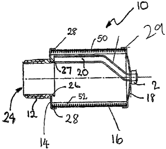
Referring to the drawings, a screen nozzle 10 embodying the present invention
comprises a means for fixing the screen element to a media retention screen in
the form
of a threaded nipple having an annular cross section 12, a first plate element
in the form
of a bottom cover 14, a screen element 16, a second plate element in the form
of a top
cover 18, a threaded rod 20, and a retention means in the form of a nut 22.
All components are made of stainless steel. The nipple is externally threaded
with a thread that matches a correspondingly threaded aperture in a plate for
insertion
of one end 24 of the nipple into a plate of a media retention screen 25. The
other end of
the nipple defines an annular end portion 26 of much reduced wall thickness
compared
to the main body of the nipple. The bottom cover 14 is in the form of a
circular plate
defining a central circular aperture 27 and an external rib 28. The end
portion 26 of the
nipple is swaged to engage the nipple in the central aperture 27 of the end
cover. As
shown in the drawings, the threaded rod 20 which has a "dog leg" bent portion
is
welded to the end portion 26 of the nipple.
The screen element 16 as shown is generally cylindrical and defines a series
of
narrow screen openings 48 sized to prevent the passage of particles of greater
than a
pre-determined diameter. Typically the nozzle's screen openings are 0.2mm wide
at
their narrowest. As illustrated in Figure 5, the openings 48 are made from a
series of
superposed circular rings 50 formed from wires having a triangular cross-
section
welded to support rods 52. The openings formed by the superposed rings are v-
shaped
and allow only two point contact with particles and are thus plug resistant.
The screen element is sandwiched between the bottom plate 14 and the top plate
18. The top plate is saucer shaped and defines a peripheral flange or rib 29.
The screen
element is retained between the top and bottom plates by means of the threaded
rod 20
which extends through an aperture 30 in the centre of the top plate and
secured by the
nut. 22 and the ribs 28, 29. Removal of the nut allows removal of the top
cover 18 and
screen from the bottom plate 14.
Figures 3 and 4 show a variant 10a of the screen nozzle shown in Figures 1 and
2 in which the threaded rod 20 is welded to the bottom cover 14 rather than to
the
nipple. Components which are present also in the screen nozzle of Figure 1
share the


CA 02538002 2006-03-07
WO 2005/032691 PCT/AU2004/001230
4
same reference numbers. Figure 4 shows the nozzle screwed into a threaded hole
in a
plate 25 of a media retention screen. It will be appreciated that in practice
the media
retention screen will define a plurality of internally threaded apertures for
receiving a
plurality of nozzles.
It will be appreciated by persons skilled in the art that numerous variations
and/or modifications may be made to the invention as shown in the specific
embodiments without departing from the spirit or scope of the invention as
broadly
described. The present embodiments are, therefore, to be considered in all
respects as
illustrative and not restrictive.

Representative Drawing
A single figure which represents the drawing illustrating the invention.
Administrative Status

For a clearer understanding of the status of the application/patent presented on this page, the site Disclaimer , as well as the definitions for Patent , Administrative Status , Maintenance Fee  and Payment History  should be consulted.

Administrative Status

Title Date
Forecasted Issue Date 2011-05-10
(86) PCT Filing Date 2004-09-10
(87) PCT Publication Date 2005-04-14
(85) National Entry 2006-03-07
Examination Requested 2008-09-03
(45) Issued 2011-05-10

Abandonment History

There is no abandonment history.

Payment History

Fee Type Anniversary Year Due Date Amount Paid Paid Date
Application Fee $400.00 2006-03-07
Maintenance Fee - Application - New Act 2 2006-09-11 $100.00 2006-03-07
Registration of a document - section 124 $100.00 2006-07-28
Maintenance Fee - Application - New Act 3 2007-09-10 $100.00 2007-08-14
Maintenance Fee - Application - New Act 4 2008-09-10 $100.00 2008-08-19
Request for Examination $800.00 2008-09-03
Maintenance Fee - Application - New Act 5 2009-09-10 $200.00 2009-09-01
Maintenance Fee - Application - New Act 6 2010-09-10 $200.00 2010-08-17
Final Fee $300.00 2011-02-24
Maintenance Fee - Patent - New Act 7 2011-09-12 $200.00 2011-09-05
Maintenance Fee - Patent - New Act 8 2012-09-10 $200.00 2012-08-08
Maintenance Fee - Patent - New Act 9 2013-09-10 $200.00 2013-09-09
Maintenance Fee - Patent - New Act 10 2014-09-10 $450.00 2014-10-01
Maintenance Fee - Patent - New Act 11 2015-09-10 $250.00 2015-08-20
Maintenance Fee - Patent - New Act 12 2016-09-12 $250.00 2016-08-17
Registration of a document - section 124 $100.00 2016-12-01
Maintenance Fee - Patent - New Act 13 2017-09-11 $250.00 2017-08-16
Maintenance Fee - Patent - New Act 14 2018-09-10 $250.00 2018-08-15
Maintenance Fee - Patent - New Act 15 2019-09-10 $450.00 2019-08-21
Maintenance Fee - Patent - New Act 16 2020-09-10 $450.00 2020-08-20
Maintenance Fee - Patent - New Act 17 2021-09-10 $459.00 2021-08-19
Maintenance Fee - Patent - New Act 18 2022-09-12 $458.08 2022-07-20
Maintenance Fee - Patent - New Act 19 2023-09-11 $473.65 2023-07-19
Owners on Record

Note: Records showing the ownership history in alphabetical order.

Current Owners on Record
BILFINGER WATER TECHNOLOGIES PTY. LTD.
Past Owners on Record
DOWSETT, MURRAY FRANK
WEATHERFORD AUSTRALIA PTY LIMITED
Past Owners that do not appear in the "Owners on Record" listing will appear in other documentation within the application.
Documents

To view selected files, please enter reCAPTCHA code :


To view images, click a link in the Document Description column. To download the documents, select one or more checkboxes in the first column and then click the "Download Selected in PDF format (Zip Archive)" or the "Download Selected as Single PDF" button.

List of published and non-published patent-specific documents on the CPD .

If you have any difficulty accessing content, you can call the Client Service Centre at 1-866-997-1936 or send them an e-mail at CIPO Client Service Centre.


Document
Description 
Date
(yyyy-mm-dd) 
Number of pages   Size of Image (KB) 
Cover Page 2006-05-11 1 47
Abstract 2006-03-07 1 69
Claims 2006-03-07 2 57
Drawings 2006-03-07 1 33
Description 2006-03-07 4 204
Representative Drawing 2006-03-07 1 9
Drawings 2010-07-21 1 26
Claims 2010-07-21 2 45
Representative Drawing 2011-04-13 1 8
Cover Page 2011-04-13 2 51
Correspondence 2006-05-08 1 26
PCT 2006-03-07 2 81
Assignment 2006-03-07 4 123
Fees 2006-03-07 1 65
Assignment 2006-07-28 3 76
Correspondence 2011-02-24 1 25
Fees 2007-08-14 1 28
Prosecution-Amendment 2008-09-03 1 31
Fees 2008-08-19 1 30
Fees 2009-09-01 1 200
Prosecution-Amendment 2010-05-21 2 46
Fees 2010-08-17 1 200
Prosecution-Amendment 2010-07-21 9 239
Fees 2013-09-09 2 56