Note: Descriptions are shown in the official language in which they were submitted.
CA 02538290 2006-03-O1
EMBOLIC COIL WITH TWISTED WIRE
BACKGROUND OF THE INVENTION
Vasoocclusive devices are used to occlude a vascular structure in the body,
such
as an aneurism. Also, blood vessels may need to be occluded, for example,
because of
cancer, wound, or stroke, for the purpose of avoiding an embolism in the case
of a
wound or stroke, and for the purpose of depriving blood to a tumor.
Various published references which describe vasoocclusive devices include
Minck Jr. Patent Publication US2003l0120302 A1; Boosfeld U.S. Patent 6,338,736-
B1;
Porter Patent Publication US2002/0193819 A1; and Berenstein et al. U.S. Patent
No.
5,718,711. Specifiically, vasoocclusive devices comprise an embolic element.
It of course is desirable for e~cient clotting to be provided by the embolic
element, after it has been placed in position within a blood vessel. One way
that this
can be done is by disrupting flow and causing turbulence, leading to increased
clotting.
By this invention, an embolic element is provided which has improved clotting
characteristics that appear after the embolic element has been inserted into
its desired
position within a blood vessel, which is often a medically urgent matter.
CA 02538290 2006-03-O1
DESCRIPTION OF THE INVENTION
By this invention, an embolic element is provided which comprises a length of
wire. The length of wire, in tum, comprises at least one flat portion which is
twisted to
define a generally helical shape, thus providing added turbulence to blood
flow, as well
as having added surface area for stimulating clotting, when compared with
round wire.
Then, it is preferred for the twisted embolic element also to generally be
bent to
essentially define a three-dimensional shape, for example a coil that extends
along a
first longitudinal axis (of the coil), with individual loops of the coil being
generally
longitudinally spaced along the axis. This coil may be a helical coil if
desired, or the
individual coil may vary in diameter. Such a coil, comprising at least a
portion of flat
wire, and, if desired, comprising a continuous, flat ribbon of wire, has a
second wire axis
extending longitudinally along the wire (which is different from the first
longitudinal axis
which extends through individual loops of the coil), with the flat wire
portions being
twisted (as stated above) about the second wire axis.
if desired, the wire used may comprise spaced, tubular wire portions,
separated
by portions of the flat wire. This may be accomplished by flattening separate
portions of
a length of tubular wire, so that the flat portions comprise flattened wire
tubing,
separated by the remaining, unflattened, tubular wire portions. However, it is
also
possible, as previously:stated, for the entire length of wire to be
substantially all flat. For
example, a single layer ribbon of wire may be used, contrary to the double
layer
portions of flattened wire tubing, separated by the unflattened, tubular wire
portions.
It may be desired for a second wire to be included in the coil of wire
described
above. This second wire may be of substantially circular, triangular,
rectangular, or oval
cross section or the like, and may have either a larger or smaller diameter
than the
2
CA 02538290 2006-03-O1
spiraled wire having flat portions. One or both of the wires may have a
diameter
ranging from 0.0015 to 0.010 inch in diameter. The two wires may have
differing
diameters, so that the diameter ratio of the larger diameter to the smaller
diameter may
be from about 2:1 up to about 10:1 in diameter (the flat wire of course does
not
precisely have a diameter, but its width may serve as the measured
"diameter."). The
materials of the two wires may be the same, but they may also vary. In some
embodiments, at least one of the wires may be made of a radiopaque material
such as
platinum alloy, tantalum, or the like. (The radiopaque material is preferably
more
radiopaque than stainless steel.) Either of the wires may be metallic or
polymeric.
For example, one or both of the wires may be made of a bioabsorbable polymer,
such as PCL/PGA (polycaprolactone/polyglycolide), which material is designed
to elicit
and increase an inflammatory response in a known manner. This bioabsorbable
polymer may be found on the surface of one or both wires, or the wire itself
may be
made of a plastic comprising the bioabsorbable polymer.
Further by this invention, a method is provided for manufacturing an embolic
element, which comprises: twisting a length of wire about a longitudinal axis
thereof, in
which the wire has at least one flat portion along its length, to cause the
flat portion to
form a first generally helical shape. Then, the length of twisted wire is
wound onto a
mandrel by bending of the wire to.:form a three-dimensional shape. This three-
dimensional shape is typically a coil, such as another helix, as stated
before. This
coiled wire may then be used to form other three-dimensional shapes, such as a
sphere, or an oval "football" shape, that can pivot flat at ends thereof for
insertion to a
blood vessel or aneurism. Also, the coiled wire as formed may have generally
3
CA 02538290 2006-03-O1
rectangular loops rather than the cylindrical loops of a typical helix, or
other shapes as
desired, comprising a three-dimensional structure, typically by bending a
length of the
twisted wire of this invention on an appropriate mandrel.
As stated before, the twisted wire may be formed from a completely flat
ribbon, or
one of varying shape, such as a wire of alternating tubular and flattened
tubular
segments. Three-dimensionally shaped forms made of this twisted wire may
comprise
substantially a cylinder formed from the wire coil (forming a second, larger
helix if
desired), or a variety of conical shapes, a sphere, a spheroidal shape, or the
like.
DESCRIPTION OF THE DRAWINGS
Referring to the drawings, Fig. 1 shows a helical embolic element in
accordance
with this invention.
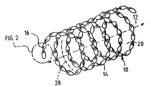
Figure 2 shows an enlarged, fragmentary view of a portion of the helical
element
of Fig. 1
Fig. 3 is an enlarged view of a portion of another embodiment of an embolic
element, comprising a wire which may be placed in a helical array as
illustrated in Fig.
1.
Fig. 4 is a similar, enlarged view of the portion of the embolic element of
Fig. 3
prior to twisting of the embolic element.
DESCRIPTION OF SPECIFIC EMBODIMENTS
Referring to the drawings, Fig. 1 illustrates a helical, embolic element in
accordance with this invention which can be mounted on a catheter in
conventional
manner and advanced through the vascular system of the patient to a site where
clotting or other blockage is medically desirable, to fill an embolism to
protect it from
4
CA 02538290 2006-03-O1
rupturing, or to block flow in a blood vessel, as previously described, and as
generally
known in the art.
Embolic element 10 can be seen to define a coil of wire, specifically a helix,
which coil extends about first longitudinal axis 12, the individual loops 14
of the coil
being generally longitudinally spaced from,each other along axis 12. The
structure
comprises, in this embodiment, a single, extending length of wire 16.
Specifically, as
indicated in Fig. 2, the length of wire 16, which comprises embolic element 10
and the
helical loops 14, further comprises a wire which is flat like a ribbon along
its entire
length, and which has been twisted about a second wire axis 18, which extends
longitudinally along wire 16, and thus is a different axis from the coil axis
12 discussed
above.
As previously stated, such a helically twisted ribbon of wire 16 serves to
provide
added turbulence to blood flow in its vicinity, when compared with a helically
arranged,
flat ribbon of wire which is not twisted, and which provides added surface
area. for
stimulating clotting, when compared with a wire of circular cross section.
Thus, when
twisted wire 16 is formed from a cylindrical mandrel 20 which is of the shape
of the
interior of helical, embolic element 10, wire 16, being wound upon it, assumes
the
shape of mandrel 20 to form another, larger helical shape than the helix
defined by wire
16 along axis 18.
Additionally, twisted wire 16 may be wound on mandrels of other shapes to form
other shaped objects. Also, the helical embolic element 10 may be wound on a
mandrel
in its own right, and combined with other lengths of helical wire to form a
three-
dimensional structure such as spherical or oval structure, which may be
mounted on a
CA 02538290 2006-03-O1
catheter in elongated form, and then released to expand to form the spherical
or oval
structure in an aneurism, for example, or an artery, to promote clotting and
to fill a pre-
determined space with clotted material, for known medical benefits.
Referring also to Figs. 3 and 4, the helical, embolic element 10 may comprise
a
wire of different structure. Specifically, rather than comprising a twisted,
flat ribbon 16
as in Fig. 2, wire 22 may comprise spaced, tubular wire portions 24, separated
by
twisted portions of flat wire 26. As shown in Fig. 4, the portions of flat
wire 26 may
comprise flattened wire tubing, so that this length of wire 22 which is used
to form an
embolic element such as helical element 10 may comprise wire tubing, not
ribbon as in
the embodiment of Fig 2. The tubing is then flattened into a series of double
layer, flat
sections 26 as shown in Fig. 4, prior to twisting of sections 26 into helical
structures as
shown in Fig. 3. The tubular wire sections which are between the flattened
wire
sections 26 then constitute tubular wire portions 24. Then, after formation of
the
flattened sections 26 in the tubular wire, as shown in Fig. 4, the tubular
wires are
twisted, resulting in twisting of the flattened wire sections 26 to form
generally helical,
twisted, flat wire portions 26 as shown in Fig. 3. This length 22 of twisted,
flat wire
segments may then be formed into another helix 10 on mandrel 20 in a manner
similar
to the previous embodiment. Such an embolic element 10 may be used in its own
right,
or it may be formed into a three-dimensional structure such as a sphere or
oval
(football) shape in the manner described above, for implantation into an
anurism or the
like, with twisted portions of the wire providing an improvement in the
clotting and other
characteristics of the structure.
6
CA 02538290 2006-03-O1
If desired, as shown in Fig. 1, a second wire 28, for example, a wire of
circular or
oval cross section, may be incorporated into embolic element coil 10 forming a
second,
helical array interleaving the helical array of wire 16.
In some embodiments, at least one of wires 16, 28 may be made of a material
that is more radiopaque than stainless steel, such as tantalum. Also, in some
embodiments at least some of the wire may carry a thrombolytic or other
material that
elicits and increases an inflammatory response. For example this may be a
bioabsorbable polymer, as previously described. Also, part or all of one of
the wires 16,
28 may be made of such a thrombolytic agent, bioabsorbable polymer, or the
like.
Thus, by this invention, an embolic element may be provided, comprising a
length of wire, in which the wire comprises at least one flat portion which is
twisted
about its longitudinal axis to define a generally helical shape, examples
being illustrated
in the drawings.
The above has been offered for illustrative purposes only, and is not intended
to
limit the scope of the claims of this application, which invention is defined
by the claims
below.
7