Note: Descriptions are shown in the official language in which they were submitted.
CA 02538563 2008-06-13
WHIPSTOCK ANCHOR
BACKGROUND OF THE INVENTION
Field of the Invention
The present invention relates to a downhole tool. More particularly, the
invention relates to a downhole tool that can be actuated in multiple,
separate ways.
More particularly still, the invention relates to a downhole anchor that can
be set either
mechanically or hydraulically in casing of a variety of sizes and weights.
Description of the Related Art
When oil and gas wells are drilled, a bore hole is formed in the earth and
typically lined with steel pipe that is cemented into place to prevent cave in
and to
facilitate the isolation of certain areas of the welibore for the collection
of
hydrocarbons. Once the steel pipe or casing is cemented into place, the
hydrocarbons
are typically gathered using a smaller string of tubulars, called production
tubing. Due
to a variety of issues, including depletion of formations adjacent the
wellbore and stuck
tools and pipe that prevent continued use of the wellbore, it is often
desirable to form
another wellbore, not from the surface but from some location along the
existing
wellbore. This new, or lateral wellbore can be lined with pipe and
hydrocarbons can
then be collected along its length. It is not uncommon to have more than one
lateral,
or sidetracked wellbore extending from a single central or parent wellbore.
Initiating a new wellbore from a cased, central wellbore requires a hole or
window be formed in the casing wall adjacent that location where the new
wellbore will
commence. Forming windows is typically done with the help of a whipstock which
is a
wedge-shaped member having a concave face that can "steer" a mill or cutter to
a side
of the casing where the window will be formed. Whipstocks and their use are
well
known and an example is shown in U.S. Patent No. 6,464,002 owned by the same
assignee as the present invention. The whipstock may be run in by itself or to
save a
trip, the whipstock
1
CA 02538563 2006-03-06
might be run in with the mill or cutter temporarily attached to its upper
edge. In any
case, the whipstock has to be anchored in the wellbore at its lower end to
keep it in
place and to resist the downward force placed upon it as the cutter moves
along its
length through the casing wall.
Various anchors are used with whipstocks and prior art anchors can be
mechanically set or hydraulically set. Mechanical anchors include those that
require a
compressive force to shear a pin and permit the anchor to assume a second, set
position. Mechanical anchors work well when the anchor is to be set at the
bottom of
a wellbore or when there is some type of restriction that has been placed in
the
wellbore, like a bridge plug. In those instances, there is a stationary
surface available
to use to generate the compressive force needed to set the mechanical anchor.
In
other instances, the anchor must be set at some point along the wellbore where
there
is no surface to act upon in order to create a compressive force. In these
instances,
the anchors can be set with pressurized fluid, but that requires a different
apparatus
and the type of anchor actually needed on a job is not always apparent in
advance.
Because of the uncertainty of equipment needed to best form a window in a
casing, there are instances in which the wrong type anchor is on site and
delays are
created as another more appropriate anchor is found. An additional problem
relates to
the fact that most prior art anchors offer little flexibility in the size
casing in which they
can operate. For example, prior art anchors with slip and cone arrangements
are
designed to increase their outer diameters minimally when they are set and
only work
properly when they are designed for the specific inner diameter casing in
which they
are used. Additionally, it is not uncommon to encounter a restriction in the
form of
garbage as even casing of a smaller inside diameter prior to reaching larger
diameter
casing where the anchor is to be set. Many prior art anchors that are small
enough to
fit through the restriction will not expand far enough to become properly set
in the
larger casing.
2
CA 02538563 2006-03-06
There is a need for an anchor that is adaptable to be operated either
mechanically or hydraulically. There is a further need for an anchor that can
be
operated in casings of varying diameters.
SUMMARY OF THE INVENTION
Embodiments of the present invention provide an anchor for a welibore that is
adaptable to be operated in at least two separate and distinct ways. In one
embodiment, a whipstock anchor is provided that can be operated either
mechanically
or hydraulically. In another embodiment, the anchor is designed to be set in
casing of
various inner diameters, even after the unset anchor is run through
restrictions. In a
further embodiment, there is a method of forming a window in a casing well
using the
whipstock anchor of the present invention.
In another embodiment, an anchor for supporting a downhole tool in a wellbore
comprises a first body and second body, the bodies slidably movable relative
to each
other to increase an outer diameter of the anchor in a set position; a biasing
member
disposed between the first body and the second body, the biasing member
arranged to
move the anchor from a run in position to the set position; and a triggering
mechanism
for initiating the movement of at least one of the bodies to the set position.
In another
embodiment, the triggering mechanism is readily adaptable to be operated
either
mechanically or hydraulically.
In yet another embodiment, a method of supporting a downhole tool in a
wellbore comprises providing the downhole tool with an anchor, the anchor
having a
first body and second body, the bodies slidably movable relative to each other
to
increase an outer diameter of the anchor in a set position; a biasing member
disposed
between the first body and the second body, the biasing member arranged to
move
the anchor from a run in position to the set position; and a triggering
mechanism for
initiating the movement of at least one of the bodies to the set position. The
method
further comprises running the downhole tool and the anchor into the wellbore
on a
tubular string; activating the anchor, thereby causing the biasing member to
move the
3
CA 02538563 2006-03-06
second body relative to the first body; and setting the anchor in the
wellbore. In
another embodiment, the method includes supplying a compressive mechanical
force
to sufficient to cause a shearable connection to fail. Alternatively, a
hydraulic force is
applied to set the anchor.
In another embodiment, the anchor is hydraulically activated and mechanically
set.
Embodiments of the anchor are suitable for use with any downhole tool
requiring support in a wellbore, including, but not limited to, whipstock,
packer, plugs,
and a wellbore tubular
BRIEF DESCRIPTION OF THE DRAWINGS
So that the manner in which the above recited features of the present
invention
can be understood in detail, a more particular description of the invention,
briefly
summarized above, may be had by reference to embodiments, some of which are
illustrated in the appended drawings. It is to be noted, however, that the
appended
drawings illustrate only typical embodiments of this invention and are
therefore not to
be considered limiting of its scope, for the invention may admit to other
equally
effective embodiments.
Figure 1 is a side, section view of a hydraulic version of the anchor of the
present invention, shown in a run-in position.
Figure 1A is an enlarged view of the anchor of Figure 1.
Figure 2 is a side, section view of the anchor of Figure 1, shown in a set
position.
Figure 2A is a schematic view of the anchor and a whipstock shown in a set
position.
Figure 3 is a section view of a mechanical version of the anchor.
4
CA 02538563 2006-03-06
Figure 4 is an isometric view of the anchor of Figure 3.
Figure 5 is a section view of the anchor along a line 5-5 of Figure 4.
Figure 6 is a schematic view of an embodiment of an anchor having dual slip
bodies.
Figure 7 is a schematic view of an embodiment of an anchor for setting a
packer.
DETAILED DESCRIPTION
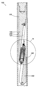
Figure 1 is a side, section view of a hydraulic version of an anchor of the
present invention, shown in a run-in position. The anchor 100 includes an
anchor
body 105 which is essentially a wedge-shaped, semicircular member with a first
surface 106 substantially parallel to the inner wall 200 of surrounding casing
and an
inner surface 107 having sides that are gradually sloped. The anchor body 105
is
connected to a whipstock which is not shown but is typically located directly
above the
anchor 100. A slip body 150 is somewhat of a mirror image of the anchor body
105
with inner and outer surfaces that are opposed to the surfaces of the anchor
body 105.
The slip body 150 typically includes at least one slip member 160 and is
substantially
free-floating relative to the anchor body 105.
Figure 1A is an enlarged view of the anchor 100 of Figure 1. Due to a shoulder
165 formed at its upper end, the slip body 150 is movable relative to the
anchor body
105 by a biasing member such as a compression spring 175. Spring 175 is
disposed
between the anchor body 105 and the slip body 150 and is retained by retention
members 176, 177 at each end. The spring 175 acts to move the two bodies 105,
150
relative to each other in order to set the anchor 100, as will be shown and
discussed
herein. A shoulder 112 formed at a lower end of the anchor body 105 permits
the
anchor body 105 to be moved relative to the slip body 150 due to movement of
the
spring 175.
5
CA 02538563 2008-06-13
As stated, the anchor 100 shown in Figures 1-2 is operable hydraulically.
Disposed between the anchor body 105 and the slip body 150 is a trigger
assembly
generally noted as 209. The assembly 209 includes not only the compression
spring
175 but also a locking mechanism to retain the spring 175 in its compressed,
run-in
position shown in Figures 1 and 1A. As shown, the locking mechanism is
hydraulically
activated to release the spring 175. The spring 175 remains compressed due to
a set
of collet fingers 201 which are housed within a groove 202 formed in retention
member
176. The fingers 201 are prevented from leaving the groove 202 by a shear
piston
205 which supports the inner surface of the collet fingers 201 as shown in
Figure 1A.
The shear piston 205 is retained in its position relative to the collet
fingers 201 by a
frangible member such as shear pins 210 at its upper end that temporarily tie
it to
retention member 176. In this respect, the trigger assembly 209 is only
activated
when a hydraulic force is applied and cannot be activated by a mechanical
force.
Advantageously, the anchor 100 cannot accidentally activate when it encounters
an
obstruction or is inadvertently dropped in the wellbore. In one embodiment,
one or
more shear pins 210 are circumferentially disposed. In another embodiment, one
or
more shear pins 210 are disposed axially relative to the each other.
At a lower end of the shear piston 205 is a seal piston 220 having a seal
member 225 and a piston surface 230 at a lower end thereof. The piston surface
230
is in fluid communication with a fluid line 235 which is visible in Figure 1A
and typically
runs upwards past the whipstock (not shown) to a tubular string that carries
the
whipstock and the anchor 100 into the wellbore. Operating a downhole tool with
pressurized fluid through a fluid line that bypasses a whipstock is well known
in the art
and an example of such an arrangement is shown in U.S. Patent No. 6,364,037
assigned to the same owner as the present application. Alternatively,
pressurized fluid
may be supplied to the anchor in any suitable manner known to a person of
ordinary
skill in the art.
Figure 2 is a side, section view of the anchor 100 of Figure 1, shown in a set
position. In this Figure, the compression spring 175 has been permitted to
relax and in
doing so has pulled the anchor body 105 and the slip body 150 towards each
other
6
CA 02538563 2006-03-06
along their sloped, inner surfaces. The result is an enlarged effective "outer
diameter"
that puts the slip member 160 in contact with the casing wall 200, thereby
fixing the
anchor 100 in the wellbore. The design of the anchor 100 includes two
important
features. First, the anchor 100 will set at virtually any point along the
length of its
"throw" or at any point between its run-in position and that point where the
compression spring 175 is essentially completely relaxed and the bodies 105,
150 can
move no further along their respective surfaces. Secondly, (as is visible in
Figure 4)
the slip body 150 is formed with one or more tapered surfaces 308, 309, 310
(also
referred to herein as "undercut") at an end thereof. In one embodiment, the
taper
surfaces 308, 309, 310 begin at the slip member 160 and tapers inward. The
surfaces
are tapered to ensure the slip 160 contacts the casing wall 200 instead of the
slip body
150 regardless of the relative positions of the anchor body 105 and slip body
150. In
Figure 1A, the slip body 150 is also provided with a tapered surface 108. In
another
embodiment, the lower portion of the anchor body 105 also includes one or more
sloped surfaces 109. With the design disclosed herein, the anchor 100 can
effectively
operate with an increased diameter of as much as 30%.
In operation, the anchor 100 is used as follows. When the anchor 100 is at the
location in the wellbore where it is to be set, pressurized fluid is
introduced into fluid
line 235 and onto the piston surface 230 of seal piston 220. The pressurized
fluid
forces the piston 220 upwards and into contact with shear piston 205. In turn,
the
shear force is exerted to the shear pins 210. At a predetermined force, shear
piston
205 causes the shear pins 210 to fail and the shear piston 205 moves out of
contact
with the collet fingers 201, thereby permitting relative movement between the
collet
fingers 201 and retention member 176. The retention member 176 is urged away
from
retention member 177 by the spring 175. Initially, a sloped side surface of
groove 202
causes the collet fingers to bend inward and move out of the groove 202 as the
spring
175 moves the retention member 176 away. Thereafter, the expansion force of
the
spring 175 moves the slip body 150, which is in contact with the retention
member
176, up the inner surface 107 of the anchor body 105, thereby moving the slip
body
150 outward into contact with the casing wall. During relative movement
between the
bodies 105, 150, the undercut of the anchor body 105 prohibits the anchor body
105
7
CA 02538563 2006-03-06
from interfering with the slip body 150 pushing the slip member 160 outward.
Also, the
undercut of the slip body 150 becomes generally parallel with the casing wall
200,
which exposes more of the slip members 160 into contact with the casing wall
200.
The foregoing action increases the outer diameter of the anchor 100 until slip
member
160 is in contact with casing wall 200. Preferably, only the slip members 160
of the
slip body 150 are in contact with casing wall 200. In the preferred
embodiment, a set
down force is applied from the surface to the anchor 100 to fully set the
anchor 100 in
the casing.
After activation, the anchor 100 provides a stable, three point contact 160,
260,
270 with the casing wall 200 to support the whipstock 250, as illustrated in
Figure 2A.
During activation, as the slip body 150 moves outward, the anchor 100 forces
the
whipstock 250 to pivot off its bottom end 260 and the whipstock tip 270 is
forced into
contact with the casing wall 200. Thus, a three point contact is created
between the
slips 260, pivot point 260, and the whipstock tip 270. This three point
contact is
particularly advantageous for performing low-side exit, i.e., a low side
lateral. As
shown in Figure 2A, due to the pivot action, the weight of the whipstock 250
is directed
upwards. When the drill bit or mill is directed toward the casing wall 200 by
the
whipstock 250, the weight of the whipstock 250 acting on the bit is
significantly
reduced, thereby facilitating the exit process.
Figure 3 is a section view of the anchor 100 having a mechanical triggering
mechanism. The availability of different triggering or actuation mechanism
options
while using identical or almost identical parts provides flexibility in
choosing the proper
actuation technique on site, if necessary. Also, the anchor 100 can be
modified with
very little effort and very few, if any, additional parts. In this manner, the
anchor 100 is
readily adaptable to operate either hydraulically or mechanically. In the
mechanically
operated embodiment, the shear piston 205 is removed along with the shear pins
210
that initially connects the shear pistons 205 to retention member 176. While
the seal
piston 230 remains, it has no function when the anchor 100 is triggered
mechanically.
In place of the shear piston and pins, external shear pins are used that hold
the anchor
100 in a set position until it is actuated downhole. While the anchor 100 can
be used
8
CA 02538563 2006-03-06
mechanically or hydraulically with the changes described herein, it will be
understood
that the anchor 100 could become effectively mechanical or hydraulic using a
variety
of modifications known to a person of ordinary skill in the art, and those
modifications
are all within the scope of this invention.
Figure 4 is an isometric view of the anchor arranged with a mechanical
triggering mechanism and includes a temporary connection between the two
bodies
105, 150 in the form of two external shear pins 300. Each external shear pin
300
extends through an aperture 301 formed in each body 105, 150 in an off-center
fashion so that they do not penetrate the inner cavity of the anchor 100 where
spring
175 is housed.
Figure 5 is a section view of the anchor of Figure 4 along a line 5-5. Visible
are
the external shear pins 300 extending between the bodies 105, 150 and fixing
them
relative to each other. Also visible in the Figure is the tongue and groove
arrangement
305 that permits the bodies 105, 150 to move past each other as the anchor 100
is
set.
In practice, the anchor of Figures 3-5 are used as follows. The anchor 100 is
transported into a wellbore at the end of a string of tubulars, usually with a
mill
temporarily attached between the string and an upper end of the whipstock.
When the
assembly reaches a predetermined depth, it is put into compression by
contacting
either a bottom of the hole or a bridge plug or some other restriction
therebelow. At a
predetermined compressive force, the shear pins 300 or other suitable trigger
devices
will fail and the device is triggered with the compression spring 175
operating to move
the bodies 105, 150 relative to each other and to increase the outer diameter
of the
anchor 100 until the slips 160 contacts casing wall 200. Thereafter, weight
can be set
down from the surface to further fix the anchor in the wellbore prior to
operating the
mill and forming the casing window.
In another embodiment, the anchor may include dual slip bodies as illustrated
in
Figure 6. The anchor 400 includes a first anchor body 405 and a first slip
body 450. A
second anchor body 425 and a second slip body 452 are disposed on the first
slip
9
CA 02538563 2006-03-06
body 450. Slip members 460 are provided on the second slip body 452 for
engagement with the casing 401. In this respect, the effective outer diameter
of the
anchor 400 is further increased when the second slip body 452 is activated. In
this
manner, an even larger diameter tubular or wellbore may be engaged by the
anchor.
Figure 7 shows an embodiment of the anchor 500 used to set a packer 530 in a
casing 501. The packer 530 is run in on a tubular 535, and the anchor 500 is
attached
to a lower portion of the tubular 535. The packer 530 may comprise an
elastomeric
material such as rubber. The anchor 500 includes an anchor body 505 having at
least
two inclines for receiving complementary slip bodies 551, 552. As the slip
bodies 551,
552 move up their respective inclines, the front portion of the slip bodies
551, 552
contact and deform the packer 530 into contact with the casing 501. In this
manner,
the anchor 500 may be used to simultaneously squeeze and set the packer 530.
It
must be noted that the packer may be set using any anchor described herein. In
this
respect, after the packer is set, set down weight may be applied to compress
the
packer into sealing engagement with the casing wall.
While the foregoing is directed to embodiments of the present invention, other
and further embodiments of the invention may be devised without departing from
the
basic scope thereof, and the scope thereof is determined by the claims that
follow.