Language selection

Search

Patent 2538638 Summary

Third-party information liability

Some of the information on this Web page has been provided by external sources. The Government of Canada is not responsible for the accuracy, reliability or currency of the information supplied by external sources. Users wishing to rely upon this information should consult directly with the source of the information. Content provided by external sources is not subject to official languages, privacy and accessibility requirements.

Claims and Abstract availability

Any discrepancies in the text and image of the Claims and Abstract are due to differing posting times. Text of the Claims and Abstract are posted:

  • At the time the application is open to public inspection;
  • At the time of issue of the patent (grant).
(12) Patent: (11) CA 2538638
(54) English Title: CONTROL UNIT HAVING A DEPLOYABLE ANTENNA
(54) French Title: BLOC DE COMMANDE A ANTENNE DEPLOYABLE
Status: Deemed expired
Bibliographic Data
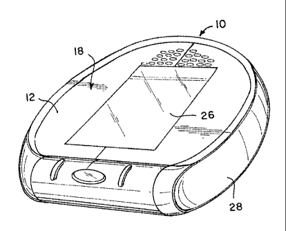
(51) International Patent Classification (IPC):
  • G08C 17/02 (2006.01)
  • A61M 5/172 (2006.01)
  • A61N 1/08 (2006.01)
  • H01Q 1/08 (2006.01)
(72) Inventors :
  • GINGGEN, ALEC (Switzerland)
  • PIPOZ, THIERRY (Switzerland)
(73) Owners :
  • CODMAN NEURO SCIENCES SARL (Switzerland)
(71) Applicants :
  • CODMAN NEURO SCIENCES SARL (Switzerland)
(74) Agent: NORTON ROSE FULBRIGHT CANADA LLP/S.E.N.C.R.L., S.R.L.
(74) Associate agent:
(45) Issued: 2014-11-25
(22) Filed Date: 2006-03-01
(41) Open to Public Inspection: 2006-09-03
Examination requested: 2011-03-01
Availability of licence: N/A
(25) Language of filing: English

Patent Cooperation Treaty (PCT): No

(30) Application Priority Data:
Application No. Country/Territory Date
11/070,998 United States of America 2005-03-03

Abstracts

English Abstract

A control unit for an implantable medical device includes a housing and electronics within the housing. The electronics control an RF emission from the control unit. An antenna is pivotably connected to the housing. The antenna is movable between a stowed position where RF emission from the antenna is prevented and a deployed position where RF emission from the antenna is permitted. To use the external control unit to effect communication between an external control unit and an implanted medical device, the user places the external control unit within electronic communication range of the implanted medical device. The control unit antenna is moved from the stowed position to a deployed position where RF emission from the antenna is permitted. RF waves are emitted from the antenna to establish communication between the external control unit and the implanted medical device.


French Abstract

Un bloc de commande pour un dispositif médical implantable comprend un boîtier et une électronique dans le boîtier. Lélectronique commande une émission RF à partir du bloc de commande. Une antenne est reliée de manière pivotante au boîtier. Lantenne est mobile entre une position arrimée où lémission RF de lantenne est empêchée et une position déployée où lémission RF de lantenne est permise. Pour utiliser le bloc de commande externe pour établir une communication entre un bloc de commande externe et un dispositif médical implanté, lutilisateur place le bloc de commande externe à portée de communication électronique du dispositif médical implanté. Lantenne du bloc de commande est déplacée de la position repliée à une position déployée où lémission RF de lantenne est permise. Lantenne émet des ondes RF pour établir une communication entre le bloc de commande externe et le dispositif médical implanté.

Claims

Note: Claims are shown in the official language in which they were submitted.


What is claimed is:
1. A control unit for an implantable medical device comprising:
a housing;
electronics, for controlling an RF emission from the control unit, being
disposed
within said housing; and
an arc shaped antenna pivotably connected to said housing, said antenna being
movable between a stowed position where RF emission from the antenna is
prevented and a
deployed position where RF emission from the antenna is permitted, in the
stowed position
the arc shaped antenna is both approximately coplanar with, and encircles the
outer periphery
of, the housing,
wherein the electronics are disposed on a pc board, the antenna defines an
antenna
plane, in the stowed position the antenna plane is approximately coplanar with
a plane
defined by the pc board, the antenna plane in the deployed position is not
coplanar with the
plane defined by the pc board.
2. The control unit of claim 1, wherein the housing has a user interface,
and the
electronics control the user interface.
3. The control unit of claim 1, wherein the housing is made of a material
that shields the
electronics from external RF waves.
4. The control unit of claim 3, wherein the housing is made of plastic.
5. The control unit of claim 1, wherein the antenna is a coaxial loop.
6. The control unit of claim 5, wherein the antenna is disposed in a
housing that permits
the transmission of RF waves therethrough.
7. The control unit of claim 1, wherein the pivotable connection between
the antenna
and the housing includes a switch electrically connected to the electronics to
detect the
position of the antenna.


8. A method for effecting communication between an external control unit
and an
implanted medical device, wherein the external control unit has a housing;
electronics
disposed on a pc board, for controlling an RF emission from the control unit,
are disposed
within the housing; an arc shaped antenna is pivotably connected to the
housing such that
said antenna moves between a stowed position and a deployed position with
respect to said
housing in only one plane, the arc shaped antenna defines an antenna plane, in
the stowed
position the antenna plane is approximately coplanar with a plane defined by
the pc board, in
the stowed position the arc shaped antenna is both approximately coplanar
with, and encircles
the outer periphery of, the housing, said method comprising the steps of:
placing the external control unit within electronic communication range of the

implanted medical device;
pivotably moving the control unit arc shaped antenna with respect to said
housing in
only one plane to a deployed position where RF emission from the arc shaped
antenna is
permitted; and
causing the emition of RF waves from the arc shaped antenna to establish
communication between the external control unit and the implanted medical
device.
9. The method of claim 8, further comprising the steps of: causing the
stopping of the
emition of RF waves from the antenna; and
pivotably moving the control unit antenna with respect to said housing in only
one
plane to a stowed position where RF emission from the antenna is prevented.
10. The method of claim 8, further comprising the step of: detecting the
position of the
antenna.
11. The method of claim 10, further comprising the step of: preventing the
emitting of RF
waves from the antenna when the position of the antenna is detected to be in a
stowed
position.
12. The method of claim 10, further comprising the step of: permitting the
emitting of RF
waves from the antenna when the position of the antenna is detected to be in a
deployed
position.
6


13. A method for effecting communication between an external control unit
and an
implanted medical device, wherein the external control unit has a housing;
electronics, for
controlling an RF emission from the control unit, are disposed within an
enclosed chamber of
the housing; an arc shaped antenna is pivotably connected to the housing such
that said
antenna moves with respect to said housing in only one plane, an arc shaped
antenna is
pivotably connected to the housing such that said antenna moves between a
stowed position
and a deployed position, in the stowed position the arc shaped antenna is both
approximately
coplanar with, and encircles the outer periphery of, the housing, said method
comprising the
steps of:
placing the external control unit within electronic communication range of the

implanted medical device;
pivotably moving the control unit arc shaped antenna with respect to said
housing in
only one plane to a deployed position where RF emission from the antenna is
permitted; and
causing the emition of RF waves from the arc shaped antenna to establish
communication between the external control unit and the implanted medical
device.
14. The method of claim 13, further comprising the steps of: causing the
stopping of the
emition of RF waves from the antenna; and
pivotably moving the control unit antenna with respect to said housing in only
one
plane to a stowed position where RF emission from the antenna is prevented.
15. The method of claim 13, further comprising the step of: detecting the
position of the
antenna.
16. The method of claim 15, further comprising the step of: preventing the
emitting of
RF waves from the antenna when the position of the antenna is detected to be
in a stowed
position.
17. The method of claim 15, further comprising the step of: permitting the
emitting of RF
waves from the antenna when the position of the antenna is detected to be in a
deployed
position.
7

Description

Note: Descriptions are shown in the official language in which they were submitted.


CA 02538638 2006-03-O1
CONTROL UNIT HAVING A DEPLOYABLE ANTENNA
FIELD OF THE INVENTION
[0001] The present invention relates generally to a control unit having a
deployable antenna.
More specifically, the present invention relates to an external control unit
for communicating
S with an implantable medical device, which control unit has an antenna that
pivots between a
stowed position and a deployed position.
BACKGROUND OF THE INVENTION
[0002] Inductive coupling has become the method of choice for energy and data
transmission between an external control unit and an implanted medical device,
such as, for
example, an infusion pump, a pacemaker or a defibrillator. To effect this
communication,
both the external control unit and the implantable medical devices must have
an antenna so
that they can communicate, usually by radio-frequency ("RF") telemetry. The
antennas are
typically made of coils of one or more turns. Optimal energy and data
transmission is
achieved with a control unit antenna made of a coaxial cable, which shield is
broken at one
point to allow for RF wave radiation. However, the position of the antenna is
usually fixed
with respect to the control unit housing. To communicate with an implanted
medical device,
RF waves are emitted from the antenna. However, these RF waves can interfere
with the
electronics inside the control unit housing and can affect the control unit
functionality.
[0003] Others have attempted to overcome these problems by using a control
unit that has an
antenna connected to the control unit by a cable. These control units are
usually the size of a
laptop computer, which is too big to be carned by the user on a daily basis.
Even if the
control unit were of a hand held size, the user is still required to manage
two pieces
simultaneously: the control unit displaying the information to manage the
communication,
and the antenna to be positioned on top of the implant during the
interrogation.
[0004] There are control units that are of a hand held size, except the
antenna in these control
units is integrated in the control unit housing. The antenna is mounted about
the electronics
within the control unit. Thus, the RF energy emitted by the antenna is limited
to minimize
the interference with the electronics within the control unit. But limiting
the RF energy also
limits the interrogation distance and the amount of energy that can be
transmitted during an
energy and data transmission.
-1-


CA 02538638 2006-03-O1
[0005] Accordingly, there is a need for a control unit for an implantable
medical device that
has an antenna that can communicate with the implantable medical device
without
interfering, or at least substantially minimizing the interference, with the
electronics inside
the control unit housing.
SUMMARY OF THE INVENTION
[0006] The present invention provides a control unit that achieves these and
other needs by
providing a housing and electronics within the housing. The electronics
control, inter alia, an
RF emission from the control unit. An antenna is pivotably connected to the
housing. The
antenna is movable between a stowed position where RF emission from the
antenna is
prevented and a deployed position where RF emission from the antenna is
permitted. To use
the external control unit to effect communication between an external control
unit and an
implanted medical device, the user places the external control unit within
electronic
communication range of the implanted medical device. The control unit antenna
is moved
from the stowed position to a deployed position where RF emission from the
antenna is
permitted. RF waves are emitted from the antenna to establish communication
between the
external control unit and the implanted medical device.
BRIEF DESCRIPTION OF THE DRAWINGS
[0007] The invention will be more fully understood from the following detailed
description
taken in conjunction with the accompanying drawings, in which:
[0008] FIG. 1 is a perspective view of a control unit in accordance with the
present invention
with an antenna in a stowed position;
[0009] FIG. lA a perspective view of a control unit in accordance with the
present invention
with an antenna in a deployed position;
[0010] FIG. 2 is a side view of the control unit with the antenna in a
deployed position;
[0011] FIG. 2A is a side view of the control unit with the antenna in a second
deployed
position;
[0012] FIG. 3 is a cross-sectional view taken along line 3-3 of FIG. 2 and
looking in the
direction of the arrows; and
2


CA 02538638 2006-03-O1
[0013] FIG. 4 is a perspective view of a right angle connector.
DETAILED DESCRIPTION OF THE INVENTION
[0014] Referring now to Figs. 1-4, a control unit 10 for an implantable
medical device is
illustrated. Control unit includes a housing 12. Electronics 13, for
controlling an RF
emission from the control unit, are disposed within housing 12. An antenna 14
is pivotably
connected to housing 12 at connection 16. Antenna 14 is movable between a
stowed position
18, as illustrated in Fig. 1, and two deployed positions 20, 22, as
illustrated in Figs. 2 and 3.
The pivotable connection 16 between the antenna and the housing includes a
switch
electrically connected to the electronics to detect the position of the
antenna. The switch
sends a signal to the electronics when the antenna is in the stowed position
18 or one of the
two deployed position 20, 22. Based on this signal, the electronics either
prevent RF
emission from the antenna when the antenna is in the stowed position 18, or
permit RF
emission from the antenna when antenna 14 is in either one of the two deployed
positions.
[0015] Antenna 14 is preferably a coaxial cable whose shield is broken at one
point to permit
the emission of RF waves. The shield is preferably broken at a location
opposite to the
pivoting connection 16. The coaxial cable is crimped and soldered to two
standard SMB
plugs 30, such as those that are commercially available from Huber and Sunher
of
Switzerland. Thus, the SMB plugs are mechanically and electrically connected
to the coaxial
cable. A pair of right angle connectors 32 are connected to the printed
circuit board 34 within
the control unit housing that has the electronics mounted thereon. The right
angle connectors
32 are electrically connected to the RF emission/reception electronics, as
well as to the SMB
plug 30. The SMB plug can freely rotate within the right angle connector
without affecting
the characteristics of the transmitted wave. A lubricant, such as Spruehoel 88
from Kontact
Chemie, Switzerland, can be introduced between the connector and the plug to
reduce wear.
[0016] Housing 12 has a user interface 26. Electronics 13 are electrically
connected to and
control user interface 26. The operator may use user interface 26 to input
programming
operating conditions for the implanted medical device. Interface 26 may
include an LCD
screen to display information and instructions to the user. A scroll dial and
two keys may be
used to allow the user to navigate through the menus. Electronics 13 are
preferably disposed
on a pc board 34 within housing 12. Antenna 14 defines an antenna plane. In
the stowed
position, the antenna plane is approximately coplanar with a plane defined by
the pc board,
which is coplanar with the user interface as well. In deployed position 20,
the antenna plane
3


CA 02538638 2006-03-O1
is not coplanar with the plane defined by the pc board. But in deployed
position 22, the
antenna plane is coplanar with the plane defined by the pc board.
[0017] Housing 12 is preferably made of a material that shields the
electronics from external
RF waves, and to decrease emission of un-wanted RF waves from the electronics.
In a
currently preferred embodiment, the housing is made of plastic. The antenna is
preferably a
coaxial loop. Antenna 14 is preferably disposed in a housing 28 that permits
the transmission
and reception of RF waves therethrough.
[0018] To use the external control unit to effect communication between an
external control
unit and an implanted medical device, the user selects the appropriate menu on
the user
interface of the control unit. The user also places the external control unit
within electronic
communication range of the implanted medical device. This is preferably
achieved by
placing the control unit on or near the body closest to where the medical
device is implanted
within the body. The control unit antenna is moved from the stowed position to
a deployed
position where RF emission from the antenna is permitted because the
electronics detect the
position of the antenna. RF waves are emitted from the antenna to establish
communication
between the external control unit and the implanted medical device. The
emitting of RF
waves from the antenna is then stopped by the electronics when the
communication has
successfully been completed. This process usually lasts between 1 and 5
seconds, and the
control unit emits an audible beep to indicate to the user that the
transmission has ended. Of
course, flashing indicating lights, vibrations, or other means may be used to
indicate to the
user that the transmission has ended. The antenna is then moved to a stowed
position where
RF emission from the antenna is prevented by the electronics.
[0019]Upon detection that the antenna is not in one of the two deployed
position, the
electronics 13 may cause a menu to be displayed on the interface 26 letting
the user know
that the antenna must be unfolded before communication can begin. By moving
the antenna
away from the control unit housing, the tuning of the antenna is improved
because the
antenna is highly sensitive to metallic objects, such as in the electronics
and the display
interface.
[0020] One skilled in the art will appreciate further features and advantages
of the invention
based on the above-described embodiments. Accordingly, the invention is not to
be limited
by what has been particularly shown and described, except as indicated by the
appended
claims.
4

Representative Drawing
A single figure which represents the drawing illustrating the invention.
Administrative Status

For a clearer understanding of the status of the application/patent presented on this page, the site Disclaimer , as well as the definitions for Patent , Administrative Status , Maintenance Fee  and Payment History  should be consulted.

Administrative Status

Title Date
Forecasted Issue Date 2014-11-25
(22) Filed 2006-03-01
(41) Open to Public Inspection 2006-09-03
Examination Requested 2011-03-01
(45) Issued 2014-11-25
Deemed Expired 2021-03-01

Abandonment History

There is no abandonment history.

Payment History

Fee Type Anniversary Year Due Date Amount Paid Paid Date
Registration of a document - section 124 $100.00 2006-03-01
Application Fee $400.00 2006-03-01
Maintenance Fee - Application - New Act 2 2008-03-03 $100.00 2008-02-13
Maintenance Fee - Application - New Act 3 2009-03-02 $100.00 2009-02-16
Maintenance Fee - Application - New Act 4 2010-03-01 $100.00 2010-02-15
Maintenance Fee - Application - New Act 5 2011-03-01 $200.00 2011-02-11
Request for Examination $800.00 2011-03-01
Maintenance Fee - Application - New Act 6 2012-03-01 $200.00 2012-02-06
Maintenance Fee - Application - New Act 7 2013-03-01 $200.00 2013-02-07
Maintenance Fee - Application - New Act 8 2014-03-03 $200.00 2014-02-05
Final Fee $300.00 2014-08-08
Maintenance Fee - Patent - New Act 9 2015-03-02 $200.00 2015-02-04
Maintenance Fee - Patent - New Act 10 2016-03-01 $250.00 2016-02-10
Maintenance Fee - Patent - New Act 11 2017-03-01 $250.00 2017-02-08
Maintenance Fee - Patent - New Act 12 2018-03-01 $250.00 2018-02-07
Maintenance Fee - Patent - New Act 13 2019-03-01 $250.00 2019-02-07
Maintenance Fee - Patent - New Act 14 2020-03-02 $250.00 2020-02-05
Owners on Record

Note: Records showing the ownership history in alphabetical order.

Current Owners on Record
CODMAN NEURO SCIENCES SARL
Past Owners on Record
GINGGEN, ALEC
PIPOZ, THIERRY
Past Owners that do not appear in the "Owners on Record" listing will appear in other documentation within the application.
Documents

To view selected files, please enter reCAPTCHA code :


To view images, click a link in the Document Description column. To download the documents, select one or more checkboxes in the first column and then click the "Download Selected in PDF format (Zip Archive)" or the "Download Selected as Single PDF" button.

List of published and non-published patent-specific documents on the CPD .

If you have any difficulty accessing content, you can call the Client Service Centre at 1-866-997-1936 or send them an e-mail at CIPO Client Service Centre.


Document
Description 
Date
(yyyy-mm-dd) 
Number of pages   Size of Image (KB) 
Claims 2006-03-01 2 67
Description 2006-03-01 4 230
Abstract 2006-03-01 1 22
Drawings 2006-03-01 2 40
Representative Drawing 2006-08-16 1 12
Cover Page 2006-08-16 1 45
Drawings 2006-05-30 2 52
Claims 2013-07-12 3 118
Representative Drawing 2014-10-23 1 16
Cover Page 2014-10-23 1 47
Correspondence 2006-03-31 1 18
Assignment 2006-03-01 9 413
Correspondence 2006-05-30 3 85
Prosecution-Amendment 2011-03-01 2 74
Prosecution-Amendment 2013-01-15 3 103
Prosecution-Amendment 2013-07-12 6 258
Correspondence 2014-08-08 1 63