Note: Descriptions are shown in the official language in which they were submitted.
CA 02538941 1998-10-30
1 _1_
FIELD MARKER FOR AGRICULTURAL IMPLEMENT
This application is a divisional of Canadian Patent Application 2,252,296
filed
October 30, 1998.
Field of Invention
This invention relates to a field marker for mounting on an agriculture
implement for generating a marked line on the ground indicative of the path of
the
implement.
Background of Invention
Field markers are commonly used on farming implements to score a mark
outward from one side of an implement when making an operating pass so that
the
mark may act as a directional guide to the operator on a subsequent pass.
Folding
field markers are also common so that long arms may be compactly folded inward
td
the implement for more compact transportation between operating locations.
A folding field marker in shown in Haukaas U.S. Patent 5,027,525
(corresponding CA 1,300,433). This patent shows a bi-fold field marker having
a
device which automatically folds the outer arm to lie along the inner arm when
an
actuator acts on the inner arm to fold it inward to the implement on which it
is
mounted. The patent also shows a breakaway device which allows the arm to fold
rearwardly when it encounters an obstacle. Col. 4, lines 34-44 describe the
breakaway operation. Col. 5, lines 3-22 further describe a spring 33 serving
two
functions, one being to provide resetting force for the break action provided
by
cradle 37, the other being to serve as a down force biasing means. The spring
provides bias to relieve some of the weight of the marker arm to vary the
downward
force with which the end of the marker scores the ground. The spring of the
Haukaas
patent, depending on soil hardness or other variables, can be difficult to
adjust to
give the most desirable combination of resetting force and down force. It is
known
that the design disclosed in the Haukaas patent is often manufactured with a
shear pin
to retain the marker in the field position and which must be replaced after a
breakaway action occurs; otherwise the resetting spring is not able to return
and
maintain the arm in the operating position.
CA 02538941 1998-10-30
-2-
The Haukaas design has a mount structure with two members connected by a
horizontal pivot to allow the outer end of the marker arm vertical movement
relative to
the implement over uneven ground. An additional member, a cradle 37, is
provided with
a vertical joint 42 shown in Fig. 5 to allow a breakaway action.
Summary of the Invention
Some objectives are to provide a field marker with improved folding arm
action,
with improved auto-resetting breakaway, which allows for independent setting
of
breakaway resetting force and down force biasing; and having fewer parts than
is
known in the prior art.
A field marker for mounting on an agricultural implement in accordance with
one aspect of the invention includes an elongated arm adapted to project
outwardly
laterally of the implement when in its operating position and being adapted to
carry a
field marking device at its outer distal end for making a score mark on the
ground, a
mount for said arm at an inner proximal end thereof allowing pivoting of said
arm
about first and second generally transverse axes whereby to allow the arm to
swing
upwardly and downwardly about the first one of said axes when operating on
uneven
ground while also allowing said arm to swing around the second one of said
axes
from its outwardly projecting operating position into another position; and a
breakaway link pivotally connected to said mount and extending alongside said
arm
to retain said arm in the operating position but which permits said arm to
swing
relative to said mount about the second axis away from its outwardly
projecting
operating position when an obstacle is encountered and a predetermined force
on said
arm has been exceeded, said breakaway link having a resetting device
associated
therewith to assist in returning said arm to the operating position once the
obstacle
has been cleared.
The breakaway link preferably extends in general parallelism to said arm when
the latter is in the operating condition.
In one embodiment the breakaway link extends from a pivot point on said
mount which is spaced from the second axis to a pivot point associated with
said arm,
said breakaway link comprising a pair of link members hinged together and
adapted
to move from (a) a slightly misaligned condition where the breakaway link acts
as a
rigid link capable of withstanding compressive forces arising from draft
forces on
said arm during normal operation whereby to inhibit the arm from swinging
about the
CA 02538941 1998-10-30
-3-
second axis on said mount to (b) a collapsed condition corresponding to a
breakaway
position of the arm after an obstacle has been encountered.
The above-noted resetting device typically comprises a biasing device which
tends to hold the breakaway link members in the slightly misaligned condition
until
the predetermined force has been exceeded and the collapsed condition of the
breakaway link members occurs.
Adjustment means may be provided for varying the degree of misalignment
between said breakaway link members whereby to enable the force causing
breakaway to be predetermined.
In another embodiment the breakaway link may include a compressible
member which compresses when the predetermined force has been exceeded to
permit swinging of the arm away from its operating position. The compressible
member preferably includes a pair of telescoping members having a compression
spring thereon to bias said members in directions away from one another.
The field marker arm typically includes inner and outer arm sections secured
together by a folding joint to permit said inner and outer arm sections to be
folded
and brought into the transport position. An actuator is preferably provided
for
effecting the folding about said folding joint of said inner and outer arm
sections into
and out of the transport position, said actuator also holding said inner and
outer arm
sections in general alignment as the arm is swung away from its operating
position
when an obstacle is encountered.
The folding joint in one embodiment includes a crank arm and a fold link
associated therewith and wherein said breakaway link extends from said pivot
point
on said mount in spaced generally parallel relation to said inner arm section
to a
pivot point on said crank arm, with the crank arm and fold link adapted to
cooperate
with the breakaway link such that as said inner arm section is rotated, said
outer arm
section rotates relative thereto.
Preferably said actuator is connected between said inner arm section and said
crank arm whereby extension and retraction of said actuator effects rotation
of the
crank arm relative to said inner arm section and at the same time by virtue of
the
interaction between the linkages defined by said breakaway link, crank arm,
mount
and inner arm section effects the rotation of the inner arm section relative
to said
mount.
CA 02538941 1998-10-30
-4-
The field marker preferably includes a biasing device acting between said
mount
and said arm to apply lifting forces to the arm whereby the field marking
device is
provided with the required degree of total down force as to enable a suitable
score mark to
be made.
The preferred embodiment of the present invention has a simplified marker
arm mounting structure having only two main members. The marker arm is
connected to the second member on a generally vertical axis to allow folding
and
unfolding of the marker arm. In the present embodiment this same vertical axis
also
provides for the breakaway action. The second member is attached to a first
member
directly on a horizontal axis. This allows the second member to pivot about
the first
member, arid allows the outer end of the marker arm vertical movement when
operating over uneven ground. In the transport position the vertical axis is
held
generally vertical or slightly inclined inwardly. In the operating position,
the vertical
axis is slightly inclined outwardly.
Further features of the invention will become apparent from the following
description and the appended claims.
BRIEF DESCRIPTION OF THE VIEWS OF DRAWINGS
Fig. 1 is a top plan view of a field marker in accordance with the present
invention in its operational position;
Figs. 2A, 2B and 2C are top plan views of the inner, middle and outer portions
respectively of the field marker as shown in Fig. 1;
Figs. 3A and 3B are top plan views respectively of the field marker as the
marker arm swings away after encountering an obstacle;
Fig. 4 is an enlarged view showing the relative position of the various
components following the breakaway action;
Figs. SA, SB and SC are top plan views showing the field marker being folded
up from its extended operating position into a folded position alongside an
agricultural
machine for transport;
Fig. 6 is a perspective view of the field marker in the fully folded transport
position;
Fig. 7 is a top view of a modified version of the field marker in operating
position;
CA 02538941 1998-10-30
-S-
Fig. 8 is a top view of the modified field marker showing a close up view of
the
compression spring in operating position;
Fig. 9 is a top view of the modified field marker in a partial breakaway
position;
Fig. 10 is a top view of the modified field marker showing a close up view of
the
compression spring in a partial breakaway position;
Fig. 11 is a top view of the disk end of a field marker having a shield or
fender
thereon and with the disk positioned to provide a less aggressive mark in
accordance
with a further aspect of the invention;
Fig. 12 is a top view of the disk end of the field marker with the disk
positioned
to provide a more aggressive mark.
DETAILED DESCRIPTION OF EMBODIMENTS
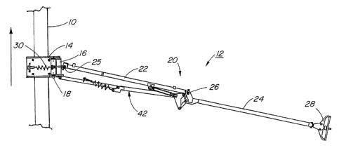
An agricultural implement 10 is shown with the field marker 12 attached to it.
The marker 12 has a mounting structure for attaching it to the implement. The
mount
structure comprises two main members 14 and 16. The mount member 14 attaches
the marker to the implement and mount member 16 is attached to mount member 14
via a generally horizontal pivot shaft 18. The marker has an elongated arm
generally
designated 20. The arm is comprised of two sections: an inner arm section 22
is
attached at one end to mount member 16 via a generally vertical pivot joint
25, and an
outer arm section 24 is pivotally attached at one end to the second end of the
inner arm
section 22 via a folding joint 26. A ground engaging element 28 is attached to
the
distal end of the outer arm section 24 for scoring a mark in the field when
operating.
In operating position the marker inner and outer arm sections 22, 24 are held
generally aligned and are extended laterally outward from the implement by
rotating
the arm 20 about the vertical pivot shaft 24 so that the marker arm 20 is
generally
transverse to the direction of travel for scoring a mark on the ground to the
side of the
implement as the implement moves across the field.
As the implement moves across the ground, the marker arm can pivot about the
horizontal pivot shaft 18 so the outer end of the arm can move vertically
relative to
the implement. This accommodates variations in ground elevation between the
implement and the outer end of the marker, so that the ground element 28 is
allowed
to follow uneven ground surfaces.
CA 02538941 1998-10-30
-6-
A coil tension spring 30 extending between an adjustable anchor on mount 14
and
the mount member 16 provides bias to raise the arm 20 upwardly, relieving some
of the
weight of the arm from the ground element 28. The tension in spring 30 is
adjustable so
the down force on the ground element resulting from the weight of the marker
arm 20 can
be adjusted. Alternately this bias force can be provided by a hydraulic
actuator acting
under controlled pressure, possibly with use of a pressure reducing-relieving
valve, and
possibly in combination with soil hardness sensing.
The marker arm 20 may be folded toward the implement so it is more compact for
transport. The spring 30 biases mount member 16 relative to mount member 14
about the
horizontal axis of shaft 18. As the marker is folded, it's center of gravity
is brought
closer to this horizontal axis and the spring 30 begins to support the marker
clear of the
ground and keeps it in a raised position when it is fully folded for
transport. As the
marker is being extended, the spring 30 keeps the marker clear of the ground
until it has
been substantially extended.
The outer arm section 24 is folded relative to the inner arm section 22 by the
action of folding crank 32 which is pivotally connected at pivot 33 near the
distal end
of the inner arm section 22 at a distance offset from the folding joint 26. A
fold link
34 is pivotally connected at one end 36 to another point on the crank 32, and
at it's
second end is pivotally connected to the outer arm section 24 at a pivot point
38 offset
from the joint 26. An actuator 40 is connected between the inner arm section
22 and
the crank 32 and is controlled to rotate the crank. The crank 32 and fold link
34
arrangement acts to fold or unfold the outer arm section 24 relative to the
inner arm
section 22 through a range of about 180 degrees when the crank 32 is operated
by the
actuator.
A breakaway link generally designated 42 is also pivotally connected to the
crank 32, link 42 extending substantially parallel to inner arm section 22.
Pin 44 by
which the actuator 40 is connected to the crank provides a convenient pivotal
connection for the link 42. It is not required that they are connected at the
same point;
however the connection point is selected so that the geometry of the parallel
breakaway link 42 in combination with the arrangement of the crank 32 and fold
link
34 causes the inner arm section 22 to rotate through a range of about 90
degrees, when
the outer arm section 24 is folded 180 degrees. The parallel breakaway link 42
is
therefor also pivotally connected to the mount member 16 at pivot point 45
offset
from pivot joint 25 by a selected amount which causes the action described
above.
CA 02538941 1998-10-30
_'7_
Various combinations of offsets between the pivot joints of the parallel link,
crank,
fold link, and arm sections can be selected for a similar resulting folding
motion.
The parallel breakaway link 42 is constructed of an inner link 42a and an
outer link
42b, pivotally connected to each other at one end by a joint 50. The inner or
proximal end
of the inner link 42a is connected to mount member 16 at pivot 45 as described
previously. The distal end of the outer link 42b is connected to the crank 32
as described
previously. The breakaway link members 42a, 42b are biased toward substantial
straight
alignment; however the joint 50 between them is maintained slightly offset of
a
straight line between pivot joints 44 and 45, to the side opposite of the
marker arm 20.
During operation, draft forces against the end of the marker arm 20 result in
compressive
forces in the parallel breakaway link 42. Since the joints are slightly
misaligned as
described above, the compressive force causes resulting reaction couples at
joints 44, 45,
and 50 which would tend to cause breakaway link members 42a, 42b to fold about
joint
50. Outer link 42b has an extension 43 on it's first end to which a resetting
tension spring
52 is attached at point 54. The resetting spring 52 is also attached to the
inner link 42a via
a threaded tension adjusting eye bolt 56. The attachment points are arranged
so that the
resetting spring 52 produces a biasing moment about joint 50 which opposes the
folding
couples. The outer link 42b is also provided with an abutment 58 at its inner
end. The
inner link 42a has a corresponding abutment 60, which rests on abutment 58
when the
outer and inner breakaway links 42a, 42b are in operational alignment, and
maintains a
selected amount of misalignment between the joints 44, 45 and 50. The abutment
60 is
made adjustable by a threaded stud so that the offset of joint 50, when the
link members
42a, 42b are in operational alignment, can be set to provide the desired
breakaway force.
The threaded adjustment bolt 56 as described above enables adjustment of the
tension of
resetting spring 52 for additionally setting the breakaway force and also for
setting the
resetting force.
The breakaway link members 42a, 42b will fold or collapse about joint 50
when the breakaway threshold is exceeded and the marker arm 12 will fold
rearwardly about joint 24. During breakaway folding the marker arms sections
22, 24
are maintained in alignment by the actuator 40 and folding joint 26, which are
not
affected by the breakaway action. The present embodiment thus allows the arm
to
swing back, away from an obstacle, rather than wrap around an obstacle, (and
without
need for a third mount member) to allow for the breakaway action.
CA 02538941 1998-10-30
_g_
The force of the resetting spring 52 can be set independently of the down
force
biasing spring 30. The resetting spring can be set with enough force so that
the
marker resets automatically in many instances.
Other advantageous features are that:
~ the fold actuator does not restrict the breakaway action;
the parallel link arrangement for folding the inner and outer arms of the
marker is more reliable than the cable arrangement of certain prior art
designs in
which there can be slip between components.
Additional Embodiments and Variations
In another embodiment of the invention, the parallel breakaway link has a
compressible section rather than a pivotal joint. In this design the spring
bears all of
the breakaway force.
A modified field marker is shown in Figs. 7-10. This marker is much the same
as described and shown in Figs. 1-6. However, the folding breakaway link 42
has
been replaced with a telescoping spring-biased breakaway link 60. The parallel
breakaway link arrangement 60 includes two telescoping members 62 and 64, and
coil compression spring 66. Spring 66 is joined to two annular mounting plates
68
and 70; with mounting plate 68 being located on member 62 and mounting plate
70
being located on member 64.
When the field marker is traveling in soil in the direction indicated and an
obstruction is encountered, the breakaway system will collapse the marker arm
to allow it
to swing back and pass the obstruction as seen in Figures 9 and 10. Member 64
is sized to
telescope in and out of member 62. When the obstruction creates a force on the
field
marker in the direction opposite the direction of travel, member 64 telescopes
into member
62. To allow this to occur, spring 66 must compress as the two mounting plates
are pushed
closer together.
As the members telescope to shorten the overall length of the parallel
breakaway link 60 and the spring compresses, the entire parallel link system
will
pivot about vertical axes 25 and 45. In this way, the field marker is able to
swing
back until the obstacle is passed. When the obstacle has been passed and the
force in
the direction opposite the direction of travel has been removed, spring 66
will push
the mounting plates 68, 70 apart and with it, push member 64 out of member 62.
The
CA 02538941 1998-10-30
_9_
parallel link system will pivot about points 25 and 45 to the full operating
position
again as shown in Fig. 7.
Although this embodiment is shown in conjunction with bi-fold markers, it
also has applications for tri-fold markers. For example, a tri-fold marker
could have
an inner section pivotally attached to the implement frame. The mount
structure 14,
16 would be located at the distal end of the inner arm section. During
breakaway, the
marker arm outer portions) would swing back about the vertical pivot axis
defined
by the mount as described previously but the inner arm section would remain
fixed
and act in effect as an extension of the implement frame.
Another aspect of the invention is concerned with the fact that as field
markers
travel through the soil, they frequently encounter obstacles. Obstacles such
as tree
branches can easily get wedged between the disk at the end of the arm and the
disk
mounting plate. Thus, then, the rotation of the disk can be hindered and a
proper
marking in the ground may not be formed.
Another frequent problem with field marker disks is that of adjusting the
angle
of the disk with respect to the direction of travel. The angled position of
the disk
dictates whether the marking left in the field is more aggressive or less
aggressive.
Therefore, the objectives of this aspect of the invention are to provide a
shield
or fender giving smooth transition from the outer arm of a field marker to the
marker
disk to allow the disk to slip cleanly off any obstacles encountered, to
provide means
of simplifying the disk angle adjustment and to provide means to maintain the
smooth
transition from the outer arm to the disk throughout the entire range of angle
adjustment.
Referring now to Figs. 11 and 12, this embodiment of the field marker arm 100
has mounting plate 102 at the end of the marker arm. Shaft 103 rotatably
mounts the
coulter disk 105. Shaft 103 is seated in a shield or fender 104 bolted to the
mounting
plate 102. The fender 104 (made from steel plate) provides a smooth transition
from
the mounting plate 102 to the disk 105. The fender 104 in essence only has to
be
located to the side facing the direction of travel. Having the fender located
on the
backside of the field marker is not necessary in order to keep debris from
being .
caught in the marker. However, a feature of the specific field marker
described above
is that it can be mounted on either side of the implement. Having a
symmetrical
fender that is located on both sides of the disk would allow the marker to be
used on
either side of the implement.
CA 02538941 1998-10-30
-10-
The fender 104 is of simple construction and provides a pair of arms 108
which extend out from the mounting plate 102 with the arms 108 having sloping
shoulder portions 109 curving smoothly around toward their distal ends 112 to
embrace diametrically opposed edge portions of the disc. The distal ends are
notched
at 110 to receive the disc edge portions loosely therein so as not to
interfere with the
disc rotation.
By virtue of the smooth shape of the fender 104 debris encountered in the
field
tends to slide along the shoulders 109 and off the arms of the fender thus
avoiding fouling
of the disc 105.
Fender 104 also includes two arcuate slots 107-that receive bolts 106 on the
mounting plate 102. This mechanism allows for very easy angle adjustment. The
bolts simply are loosened, the angle adjusted and bolts retightened. Figure 11
shows
the orientation of the disk for a less aggressive marking while Figure 12
shows the
orientation of the disk for a more aggressive marking.
This fender mount system can be implemented on a field marker of any
configuration and any folding sequence.
Preferred embodiments of the invention have been described and illustrated by
way of example. Those skilled in the art will realize that various
modifications and
changes may be made while still remaining within the spirit and scope of the
invention. Hence the invention is not to be limited to the embodiments as
described
but, rather, the invention encompasses the full range of equivalencies as
defined by
the appended claims.