Note: Descriptions are shown in the official language in which they were submitted.
CA 02539052 2006-03-09
DYNAMIC OPTICAL WAVEGUIDE SENSOR
BACKGROUND OF THE INVENTION
Field of the Invention
Embodiments of the present invention generally relate to optical waveguide
sensors, and more particularly to a fiber Bragg grating optical waveguide
sensors that
dynamically senses strain induced by a stimuli acting upon a transduction
mechanism.
Description of the Related Art
A fiber Bragg grating (FBG) is an optical element that is formed by a photo-
induced periodic modulation of the refractive index of an optical waveguide's
core. An
FBG element is highly reflective to light having wavelengths within a narrow
bandwidth
that is centered at a wavelength that is referred to as the Bragg wavelength.
Other
wavelengths pass through the FBG without reflection. The Bragg wavelength
itself is
dependent on physical parameters, such as temperature and strain, that impact
on the
refractive index. Therefore, FBG elements can be used as sensors to measure
such
parameters. After proper calibration, the Bragg wavelength acts is an absolute
measure of the physical parameters.
One way of using fiber Bragg grating elements as sensors is to apply strain
from
an elastic structure (e.g., a diaphragm, bellows, etc.) to a fiber Bragg
grating element.
For example, U.S. Pat. No. 6,016,702, issued Jan. 25, 2000, entitled "High
Sensitivity
Fiber Optic Pressure Sensor for Use in Harsh Environments" by inventor Robert
J.
Maron discloses an optical waveguide sensor in which a compressible bellows is
attached to an optical waveguide at one location while a rigid structure is
attached at
another. A fiber Bragg grating (FBG) is embedded within the optical waveguide
between the compressible bellows and the rigid structure. When an external
pressure
change compresses the bellows the tension on the fiber Bragg grating is
changed,
which changes the Bragg wavelength.
1
CA 02539052 2006-03-09
Another example of using fiber Bragg grating elements as pressure sensors is
presented in U.S. Pat. No. 6,422,084, issued July 23, 2002, entitled "Bragg
Grating
Pressure Sensor" by Fernald, et al. That patent discloses optical waveguide
sensors in
which external pressure longitudinally compresses an optical waveguide having
one or
more fiber Bragg grating. The optical waveguide can be formed into a "dog
bone"
shape that includes a fiber Bragg grating and that can be formed under tension
or
compression to tailor the pressure sensing characteristics of the fiber Bragg
grating.
Another fiber Bragg grating outside of the narrow portion of the dog bone can
provide
for temperature compensation.
10 While the foregoing pressure sensing techniques are beneficial, those
techniques may not be suitable for all applications. Therefore, fiber Bragg
grating
techniques suitable for dynamically sensing varying parameters such as
pressure and
strain would be useful. Also useful would be fiber Bragg grating techniques
that provide
for both static and dynamic measurements of parameters.
SUMMARY OF THE INVENTION
Embodiment of the present invention generally provides for optical waveguide
measurement techniques that are suitable for sensing dynamically varying
physical
parameters such as pressure and strain. Furthermore, embodiments of the
present
invention also provide for both static and dynamic measurements of physical
20 parameters.
The foregoing and other objects, features, and advantages of the present
invention will become more apparent in light of the following detailed
description of
exemplary embodiments thereof.
BRIEF DESCRIPTION OF THE DRAWINGS
25 So that the manner in which the above recited features of the present
invention
can be understood in detail, more particular descriptions of the invention,
briefly
summarized above, may be had by reference to embodiments, some of which are
2
CA 02539052 2006-03-09
illustrated in the appended drawings. It is to be noted, however, that the
appended
drawings illustrate only typical embodiments of this invention and are
therefore not to
be considered limiting of its scope, for the invention may admit to other
equally effective
embodiments.
Figure 1 illustrates an optical waveguide sensor having a sequence of sensors
disposed along the optical waveguide;
Figure 2 illustrates a dog bone pressure sensor having both a fiber Bragg
grating
pressure sensor and a fiber Bragg grating temperature sensor;
Figure 3 illustrates a swept frequency optical waveguide measurement system
that can be used for both dynamic and static measurements;
Figure 4 schematically illustrates parking a narrow line width laser on the
slope
of a fiber Bragg grating; and
Figure 5 schematically illustrates an optical waveguide AC strain measurement
system.
DETAILED DESCRIPTION OF THE PREFERRED EMBODIMENT
The present invention provides for optical waveguide measurement systems that
are suitable for sensing dynamically varying physical parameters such as
pressure and
strain. Some embodiments of the present invention enable both static and
dynamic
measurements of physical parameters. Embodiments of the present invention are
suitable for use in harsh environments as found in oil and/or gas wells,
engines,
combustion chambers, etc.
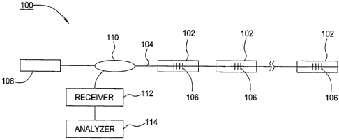
Figure 1 illustrates an optical waveguide sensor system 100 having a sequence
of sensors 102 disposed along an optical waveguide 104. Each sensor 100
includes at
least one fiber Bragg grating 106. Depending on the application and the
specific
configuration, the sensor system 100 can be operated in various ways. For
example, a
tunable light source 108, such as a tunable laser or a broadband light source
mated
3
CA 02539052 2006-03-09
with a tunable filter, can inject light that is swept over a bandwidth into a
coupler 110.
The coupler 110 passes the light onto the optical waveguide 104. Reflections
at the
Bragg wavelengths of the various fiber Brag gratings 106 occur. The coupler
110
passes those reflections into a receiver 112. The fiber Bragg gratings 106 are
disposed
such that the Bragg wavelengths depend on a physical parameter of interest.
The
output of the receiver 112 is passed to an analyzer 114 that determines from
the Bragg
wavelengths a measurement of the physical parameter of interest sensed by the
sensors 102. Alternatively, if each sensor in a string has a different
wavelength, then a
broadband light source without a tunable filter can be used as a signal can
still be
received from each sensor at the receiver 112.
Figure 2 illustrates an exemplary sensor 102 that is suitable for measuring
parameters such as pressure and strain. The optical waveguide 104 includes a
narrow
core 202 that passes through a relatively thick cladding layer 204. That
cladding layer
is thinned around the fiber Bragg grating 106 to form a narrow section that
includes the
15 fiber Bragg grating 106. Around the narrow section is a shell 206 that is
integrally
mated with the cladding layer 204. To adjust the characteristics of the
resulting sensor
102, when the shell 206 is mated with the cladding layer 204 the optical
waveguide 104
could be under tension, under a slight compression (a large compression would
tend to
buckle the narrow section), or, more typically, unbiased. The result is a
fiber Bragg
grating having a particular Bragg wavelength. When external pressure or strain
is
applied to the shell 206, longitudinal tension or compression occurs and the
Bragg
wavelength changes. A second fiber Bragg grating 212 outside of the narrow
section
can be included to provide a reference inside of the shell 206 for temperature
compensation.
25 Figure 3 iNustrates a tunable laser method of using optical sensors 102 to
provide dynamic (AC) measurements. In that method, a tunable laser 302
produces a
narrow line width laser pulse 304 that is coupled by a coupler 110 into an
optical
waveguide 104 having at least one optical sensor 102. The wavelength of the
narrow
line width laser pulse 304 is swept through a wavelength band that includes
the Bragg
wavelength of the fiber Bragg grating 106 in the optical sensor 102. The shape
function
4
CA 02539052 2006-03-09
306 of the fiber Bragg grating 106, that is, its amplitude (Y-axis) verses
wavelength (X-
axis) characteristics, is determined by a high frequency receiver 112 and an
analyzer
114. Referring now to Figure 4, a particular power level, say the 3dB point
down from
the peak 402, is selected by the analyzer. Then, the analyzer sets the
wavelength of
the tunable laser 302 to the wavelength 404 that corresponds to the selected
power
level. Thus, the wavelength of the tunable laser 302 is set at a specific
wavelength that
is on the shape function 306. Then the intensity of the reflected light is
monitored.
Variations in the intensity correspond to dynamic pressure changes impressed
on the
optical sensor 102. The high frequency receiver 112 and the analyzer 114 can
provide
wavelength and amplitude information from the variations in intensity.
The foregoing method illustrated with the assistance of Figures 3 and 4 can
also
provide static pressure measurements. Since the position of the shape function
306
with respect to wavelength (shown in X-axis) depends on static pressure, the
analyzer
114 can determine static pressure based on the wavelength position 409 of the
peak
15 410 fiber Bragg grating reflection. It should be understood that while
Figures 3 and 4
only illustrate one optical sensor 102 the optical waveguide 104 could have
numerous
optical sensors 102.
In addition to providing dynamic pressure measurements, the principles of the
present invention also provide for determining dynamic (AC) strain. One
technique of
20 doing this is illustrated in Figure 5. As shown, a light source 500
launches light into port
1 of a 4 port circulator 502. That light is emitted from port 2 of the
circulator 502 into an
optical waveguide 104. That waveguide includes a sensor 503 that is comprised
of two
fiber Bragg gratings, 504 and 506. The gratings 504 and 506, which have
different
Bragg wavelengths a1 and X12, respectively, are separated by a long period
grating 508
25 that is in a strain sensing field. When the light reaches gratings 504 and
506 those
gratings reflect the Bragg wavelengths X11 and X12, respectively. However,
there is a
strain induced loss within the long period grating 508. Since ~I1 is reflected
by grating
504 it signal is not attenuated by the long period grating 508, and thus the
power of
wavelength ~i1 can act as a reference power. However, the power of X12 depends
on
30 the loss within the long period grating 508, which in turn depends on the
applied strain.
5
CA 02539052 2006-03-09
Thus the ratio of the powers of a1 and X12 is a measure of strain on the long
period
grating. The long period grating 508 can also be disposed to measure strain
due to
applied pressure or some other stimuli.
Still referring to Figure 5, the reflected light X11 and a2 on the optical
waveguide
104 enters the circulator 502. Wavelength a2 passes through a wavelength
filter 510,
but wavelength a1 is reflected. The passed wavelength X12 is received and
amplified by
a first receiver 514. The output of receiver 514 is passed to an analyzer 516.
Meanwhile, X11 is output from port 4 of the circulator 502. The wavelength X11
is received
and amplified by a second receiver 518. The output of the second receiver 518
is
10 applied to the analyzer 516. The analyzer 516 compares the ratio of the
reflected
wavelengths and determines the dynamic (AC) strain applied to the long period
grating
508.
While the foregoing is directed to embodiments of the present invention, other
and further embodiments of the invention may be devised without departing from
the
basic scope thereof, and the scope thereof is determined by the claims that
follow.
6