Note: Descriptions are shown in the official language in which they were submitted.
CA 02539119 2006-03-15
WO 2005/030087 PCT/US2004/031488
Facet Joint Replacement
Reference To Pending Prior Applications
The present application claims the benefit of:
(i) pending prior U.S. Provisional Patent Application Serial No. 60/505,199,
filed
09/23/03 by E. Marlowe Goble et al. for FACET JOINT REPLACEMENT (Attorney's
Docket No. MED-1 CIP PROV).
(ii) pending prior U.S. Provisional Patent Application Serial No. 10/687,865,
filed
10/17/2003 by E. Marlowe Goble et al, for FACET JOINT REPLACEMENT (Attorney's
Docket No. MED-1 CIP).
The two above-identified documents are hereby incorporated herein by
reference.
Background Of The Invention
Field Of The Invention
The present invention relates to surgical devices and methods to replace a
damaged,
diseased, or otherwise painful spinal facet joint.
Description Of Related Art
Traumatic, inflammatory, metabolic, and degenerative disorders of the spine
can
produce debilitating pain that can have severe socioeconomic and psychological
effects.
One of the most common surgical interventions today is arthrodesis, or spine
fusion, of one
or more motion segments, with approximately 300,000 procedures performed
annually in
the United States. Clinical success varies considerably, depending upon
technique and
indications, and consideration must be given to the concomitant risks and
complications.
For example, Tsantrizos and Nibu have shown that spine fusion decreases
function by
limiting the range of motion for patients in flexion, extension, rotation, and
lateral bending.
Furthermore, Khoo and Nagata have shown that spine fusion creates increased
stresses and,
therefore, accelerated degeneration of adjacent non-fused motion segments.
Additionally,
pseudoarthrosis, as a result of an incomplete or ineffective fusion, may
reduce or even
eliminate the desired pain relief for the patient. Finally, the fusion device,
whether artificial
or biological, may migrate out of the fusion site.
Recently, several attempts have been made to recreate the natural biomechanics
of
the spine by use of an artificial disc. Artificial discs provide for
articulation between
FSI-06
CA 02539119 2006-03-15
WO 2005/030087 PCT/US2004/031488
2
vertebral bodies to recreate the full range of motion allowed by the elastic
properties of the
natural intervertebral disc that directly connects two opposed vertebral
bodies.
However, the artificial discs proposed to date do not fully address the
mechanics of
motion of the spinal column. In addition to the intervertebral disc, posterior
elements called
the facet joints help to support axial, torsional and shear loads that act on
the spinal column.
Furthermore, the facet joints are diarthroidal joints that provide both
sliding articulation and
load transmission features. The effects of their absence as a result of
facetectomy was
observed by Goh to produce significant decreases in the stiffness of the
spinal column in all
planes of motion: flexion and extension, lateral bending, and rotation.
Furthermore,
contraindications for artificial discs include arthritic facet joints, absent
facet joints, severe
facet joint tropism or otherwise deformed facet joints, as noted by Lemaire.
U. S. Patent Number Re. 36,758 to Fitz discloses an artificial facet joint
where the
inferior facet, the mating superior facet, or both, are resurfaced.
U. S. Patent Number 6,132,464 to Martin discloses a spinal facet joint
prosthesis that
is supported on the posterior arch of the vertebra. Extending from this
support structure are
inferior and/or superior blades that replace the cartilage at the facet joint.
Like the Fitz
design, the Martin prosthesis generally preserves existing bony structures and
therefore does
not address pathologies that affect the bone of the facets in addition to
affecting the
associated cartilage. Furthermore, the Martin invention requires a mating
condition between
the prosthesis and the posterior arch (also known as the lamina) that is a
thin base of curved
bone that carries all four facets and the spinous process. Since the posterior
arch is a very
complex and highly variable anatomic surface, it would be very difficult to
design a
prosthesis that provides reproducible positioning to correctly locate the
cartilage-replacing
blades for the facet joints.
Another approach to surgical intervention for spinal facets is provided in
W09848717A1 to Villaret. While Villaret teaches the replacement of spine
facets, the
replacement is interlocked in a manner to immobilize the joint.
Facet joint replacement in conjunction with artificial disc replacements
represent a
holistic solution to recreating a fully functional motion segment that is
compromised due to
disease or trauma. Together, facet joint and disc replacement can eliminate
all sources of
pain, return full function and range of motion, and completely restore the
natural
biomechanics of the spinal column. Additionally, degenerative or traumatized
facet joints
FSI-06
CA 02539119 2006-03-15
WO 2005/030087 PCT/US2004/031488
3
may be replaced in the absence of disc replacement when the natural
intervertebral disc is
unaffected by the disease or trauma.
It would therefore be an improvement in the art to provide a vertebral facet
replacement device and method that replaces a bony portion of the facets so as
to remove the
source of arthritic, traumatic, or other disease mediated pain.
Summary Of The Invention
It is an object of the invention to provide an artificial vertebral facet that
replaces the
cartilage and a portion of the bone of a facet.
It is a further object of the invention to provide a method for preparing a
vertebra for
the installation of an artificial vertebral facet.
It is another object to provide a method for replacing a spinal facet.
It is yet another object of the invention to provide a total vertebral facet
joint
replacement.
In the preferred embodiment, an inferior facet of a superior vertebra is
resected at the
base of the facet where it connects to the posterior arch. The fm of a
prosthetic inferior facet
is pressed into the interior bone space of the posterior arch. Alternatively,
a tool, such as a
broach or punch, may be used to first prepare a space for the fm within the
posterior arch.
Alternatively, or in addition, a superior facet of an inferior vertebra that
articulates
with the inferior facet is resected at the base of the facet where it connects
to the pedicle.
The post of a prosthetic superior facet is pressed into the interior bone
space of the pedicle.
Alternatively, a tool, such as a broach or punch, may be used to first prepare
a space for the
post within the pedicle.
The post and the fm may be porous coated to promote bone ingrowth in order to
achieve long term fixation. Long term fixation is provided by a press fit
between the post or
fin and the internal surface of the bone. The porous coating may carry
osteoconductive
agents, such as hydroxylapatite, calcium sulfate, or demineralized bone
matrix.
Alternatively, the porous coating may carry osteoinductive agents, such as
bone
morphogenic proteins, including rhBMP-2 and rhBMP-7.
Another embodiment of the present invention provides a flange extending from
the
prosthetic facet. The flange is oriented relative to the body of the
prosthesis such that when
the flange is placed against the pedicle and in a manner such that the planar
surface of the
FSI-06
CA 02539119 2006-03-15
WO 2005/030087 PCT/US2004/031488
4
flange is perpendicular to the axis of the pedicle interior bone canal, the
articulating surface
of the prosthesis will be properly positioned to match the articulating
surface of the natural
facet. The flange includes a hole for the passage of a fastener to securely
attach the
prosthesis to the pedicle. The fastener can be a screw, spike, tack, staple,
or the like.
In one form of the invention, there is provided a prosthesis for the
replacement of at
least a portion of the bone of a facet located on a mammalian vertebra,
comprising:
an articulating surface that articulates with another facet;
a bone contacting surface that contacts a surface of the vertebra, said
articulating
surface being connected to said bone contacting surface; and
a fixation element that attaches said bone contacting surface to the vertebra,
said
fixation element being adapted for implantation into an interior bone space of
a pedicle of
the vertebra;
wherein said prosthesis is configured so that no portion of said prosthesis
contacts
the posterior arch of said vertebra.
In another form of the present invention, there is provided a prosthesis for
the
replacement of at least a portion of the bone of a facet located on a
mammalian vertebra,
comprising:
an articulating surface that articulates with another facet;
a bone contacting surface that contacts a surface of the vertebra, said
articulating
surface being connected to said bone contacting surface; and
a fixation element that attaches said bone contacting surface to the vertebra,
said
fixation element being adapted for implantation into an interior bone space of
a pedicle of
the vertebra;
wherein said bone contacting surface is configured to engage a resected
surface of
the vertebra.
In another form of the present invention, there is provided a prosthesis for
the
replacement of at least a portion of the bone of a facet located on a
mammalian vertebra,
comprising:
an articulating surface that articulates with another facet;
a bone contacting surface that contacts a surface of the vertebra, said
articulating
surface being connected to said bone contacting surface; and
FSI-06
CA 02539119 2006-03-15
WO 2005/030087 PCT/US2004/031488
a fixation element that attaches said bone contacting surface to the vertebra,
said
fixation element being adapted for implantation into an interior bone space of
a pedicle of
the vertebra;
wherein said bone contacting surface has a smaller surface area than said
articulating
surface.
In another form of the present invention, there is provided a prosthesis for
the
replacement of at least a portion of the bone of a facet located on a
mammalian vertebra,
comprising:
an articulating surface that articulates with another facet;
a bone contacting surface that contacts a surface of the vertebra, said
articulating
surface being connected to said bone contacting surface; and
a fixation element that attaches said bone contacting surface to the vertebra,
said
fixation element being adapted for implantation into an interior bone space of
a pedicle of
the vertebra;
wherein said articulating surface comprises a wing ear extending upward from
said
bone contacting surface.
In another form of the present invention, there is provided a prosthesis for
the
replacement of at least a portion of the bone of a facet located on a
mammalian vertebra,
comprising:
an articulating surface that articulates with another facet;
a bone contacting surface that contacts a surface of the vertebra, said
articulating
surface being connected to said bone contacting surface; and
a fixation element that attaches said bone contacting surface to the vertebra,
said
fixation element being adapted for implantation into an interior bone space of
a pedicle of
the vertebra;
wherein said articulating surface is substantially planar and extends adjacent
to the
pedicle.
In another form of the present invention, there is provided a prosthesis for
the
replacement of at least a portion of the bone of a facet located on a
mammalian vertebra,
comprising:
an articulating surface that articulates with another facet;
FSI-06
CA 02539119 2006-03-15
WO 2005/030087 PCT/US2004/031488
6
a bone contacting surface that contacts a surface of the vertebra, said
articulating
surface being connected to said bone contacting surface; and
a fixation element that attaches said bone contacting surface to the vertebra,
said
fixation element being adapted for implantation into an interior bone space of
a pedicle of
the vertebra;
wherein said articulating surface is substantially planar and extends
substantially
parallel to said fixation element.
In another form of the present invention, there is provided a prosthesis for
the
replacement of at least a portion of the bone of a facet located on a
mammalian vertebra,
comprising:
an articulating surface that articulates with another facet;
a bone contacting surface that contacts a surface of the vertebra, said
articulating
surface being connected to said bone contacting surface; and
a fixation element that attaches said bone contacting surface to the vertebra,
said
fixation element being adapted for implantation into an interior bone space of
a pedicle of
the vertebra;
wherein said fixation element clamps said bone contacting surface to a
resected
surface of the vertebra.
In another form of the present invention, there is provided a prosthesis for
the
replacement of at least a portion of the bone of a facet located on a
mammalian vertebra,
comprising:
an articulating element that articulates with another facet;
a bone contacting element that contacts a surface of the vertebra, said
articulating
element being connected to said bone contacting element; and
a fixation element that attaches said bone contacting element to the vertebra,
said
fixation element being adapted for implantation into an interior bone space of
a pedicle of
the vertebra;
wherein said prosthesis is configured so that no portion of said prosthesis
contacts
the posterior arch of said vertebra.
In another form of the present invention, there is provided a prosthesis for
the
replacement of at least a portion of the bone of a superior facet located on a
mammalian
FSI-06
CA 02539119 2006-03-15
WO 2005/030087 PCT/US2004/031488
7
vertebra and for replacement of at least a portion of the bone of an inferior
facet located on
the same mammalian vertebra, comprising:
a superior articulating element that articulates with another facet;
a superior bone contacting element that contacts one of a surface of the
vertebra or
another element contacting a surface of the vertebra, said superior
articulating element being
connected to said superior bone contacting element; and
an inferior articulating element that articulates with another facet;
an inferior bone contacting element that contacts one of a surface of the
vertebra or
another element contacting a surface of the vertebra, said inferior
articulating element being
connected to said inferior bone contacting element; and
a fixation element that attaches said superior bone contacting element and
said
inferior bone contacting element to the vertebra, said fixation element being
adapted for
implantation into an interior bone space of a pedicle of the vertebra;
wherein said prosthesis is configured so that no portion of said prosthesis
contacts
the posterior arch of said vertebra.
In another form of the present invention, there is provided a prosthesis for
the
replacement of at least a portion of the bone of a superior facet located on a
first mammalian
vertebra and for replacement of at least a portion of the bone of an inferior
facet located on a
second mammalian vertebra, comprising:
a superior articulating element that articulates with another facet;
a superior bone contacting element that contacts one of a surface of the first
vertebra
or another element contacting a surface of the vertebra, said superior
articulating element
being connected to said superior bone contacting element;
a first fixation element that attaches said superior bone contacting element
to the first
vertebra, said first fixation element being adapted for implantation into an
interior bone
space of a pedicle of the vertebra; and
an inferior articulating element that articulates with another facet;
an inferior bone contacting element that contacts one of a surface of the
second
vertebra or another element contacting a surface of the vertebra, said
inferior articulating
element being connected to said inferior bone contacting element; and
FSI-06
CA 02539119 2006-03-15
WO 2005/030087 PCT/US2004/031488
8
a second fixation element that attaches said inferior bone contacting element
to the
second vertebra, said second fixation element being adapted for implantation
into an interior
bone space of a pedicle of the vertebra; and
wherein said prosthesis is configured so that no portion of said prosthesis
contacts
the posterior arches of said first and second vertebrae.
In another form of the present invention, there is provided a method for
replacing at
least a portion of the bone of a facet located on a mammalian vertebra,
comprising:
providing:
an articulating surface that articulates with another facet;
a bone contacting surface that contacts a surface of the vertebra, said
articulating surface being connected to said bone contacting surface; and
a fixation element that attaches said bone contacting surface to the vertebra,
said fixation element being adapted for implantation into an interior bone
space of a pedicle
of the vertebra;
wherein said prosthesis is configured so that no portion of said prosthesis
contacts the posterior arch of said vertebra; and
positioning said bone contacting surface against a surface of the vertebra;
and
attaching said bone contacting surface to the vertebra using said fixation
element.
In another form of the present invention, there is provided a prosthesis for
the
replacement of at least a portion of the bone of a facet located on a
mammalian vertebra,
comprising:
an articulating element that articulates with another facet;
a bone contacting element that contacts a surface of the vertebra or another
element
contacting a surface of the vertebra, said articulating element being
connected to said bone
contacting element; and
a fixation element that attaches said bone contacting element to the vertebra,
said
fixation element being adapted for implantation into an interior bone space of
a pedicle of
the vertebra;
wherein said prosthesis is configured so that no portion of said prosthesis
contacts
the posterior arch of said vertebra.
In another form of the present invention, there is provided a method for
replacing at
least a portion of the bone of a facet located on a mammalian vertebra,
comprising:
FSI-06
CA 02539119 2006-03-15
WO 2005/030087 PCT/US2004/031488
9
an articulating element that articulates with another facet;
a bone contacting element that contacts a surface of the vertebra or another
element
contacting a surface of the vertebra, said articulating element being
connected to said bone
contacting element; and
S a fixation element that attaches said bone contacting element to the
vertebra, said
fixation element being adapted for implantation into an interior bone space of
a pedicle of
the vertebra;
wherein said prosthesis is configured so that no portion of said prosthesis
contacts
the posterior arch of said vertebra;
positioning said bone contacting surface against a surface of the vertebra or
another
element contacting a surface of the vertebra; and
attaching said bone contacting surface to the vertebra using said fixation
element.
Because the present invention allows for the individual replacements of
facets, only
comprised facets need be replaced. For example, if only one facet is affected
by disease or
trauma, it can be resected and replaced with a facet prosthesis that
articulates with an
opposing natural facet.
The present invention has numerous advantages over the prior art. One
advantage is
that the quality of attachment of the prosthesis is improved. The present
invention provides
a precise press fit into bones, as opposed to relying on prosthetic surfaces
mating with
highly complex and variable external surfaces of the vertebra, such as the
posterior arch or
facet. Another advantage is that the optional porous coating is placed into
interior bone
spaces where porous coatings have proven to achieve bone ingrowth for
excellent long term
fixation strength. This ability to achieve bone ingrowth is uncertain for the
prior art devices
that engage the external bone surfaces of the vertebra. Yet another advantage
lies in the
removal of the facet bone structure; where the facet bone is involved in the
disease
pathology or the trauma that compromised the articular or cartilaginous
surface of the facet,
resection provides a means for ensuring that all pain associated with the
disease or trauma is
removed.
The above, and other objects, features and advantages of the present
invention, will
become apparent from the following description which is to be read in
conjunction with the
accompanying drawings.
FSI-06
CA 02539119 2006-03-15
WO 2005/030087 PCT/US2004/031488
Brief Description Of The Drawings
Fig. 1 is a perspective view of a portion of the spine;
Fig. 1A is a dorsal view of the portion of the spine shown in Fig. 1;
Fig. 2 is a lateral view of a facet joint reconstructed in accordance with the
present
5 invention;
Fig. 3 is a dorsal view of the facet joint shown in Fig. 2;
Fig. 4 is a perspective view of the implanted left inferior facet prosthesis
shown in
Figs. 2 and 3;
Fig. 5 is a perspective view of the left inferior facet prosthesis shown in
Figs. 2 and
10 3;
Fig. 6 is a cranial view of the implanted left superior facet prosthesis shown
in Figs.
2 and 3;
Fig. 7 is a perspective view of the left superior facet prosthesis shown in
Figs. 2 and
3;
Fig. 8 is a perspective view of an alternate implanted left inferior facet
prosthesis;
Fig. 9 is a perspective view of an alternate left inferior facet prosthesis;
Fig. 10 is a lateral view of an alternative reconstructed facet joint;
Fig. 11 is a dorsal view of an alternative reconstructed facet joint;
Fig. 12 is a perspective view of the implanted left inferior facet prosthesis
shown in
Figs. 10 and 11;
Fig. 13 is a perspective view of the alternative left inferior facet
prosthesis shown in
Figs. 10 and 11;
Fig. 14 is a cranial view of the alternative implanted left superior facet
prosthesis
shown in Figs. 10 and 1 l;
Fig. 15 is a perspective view of the alternative left superior facet
prosthesis shown in
Figs. 10 and 11;
Fig. 16 is a perspective view of an alternate bearing surface for the superior
facet
prosthesis shown in Fig. 15;
Fig. 17 is a dorsal view of a single intact vertebra;
Fig. 18 is a lateral view of the same intact vertebra shown in Fig. 17;
Fig. 19 is a dorsal view of the same vertebra of Fig. 17 and Fig. 18, with a
portion of
the superior facet resected and a portion of the inferior facet resected;
FSI-06
CA 02539119 2006-03-15
WO 2005/030087 PCT/US2004/031488
11
Fig. 20 is a lateral view of the resected vertebra shown in Fig. 19;
Fig. 21 is a dorsal view of the same resected vertebra shown in Fig. 18 and
Fig. 19
with a fixation element placed through the first superior resection surface
and into the
pedicle bone;
Fig. 22 is a dorsal view showing the resected verebra, the fixation element,
and a
superior facet prosthesis;
Fig. 23 is a dorsal view of the vertebra and the implant of Fig. 23 and also
showing
the addition of an inferior facet prosthesis;
Fig. 24 is a dorsal view of the implant and vertebra of Fig. 23 and also
showing the
addition of an enlarged head that has the shape of a locking nut;
Fig. 25 is an isometric posteriolateral view of a vertebra with an assembled
implant
comprising a fixation element, superior facet prosthesis, and a locking nut;
Fig. 26 is a cross-sectional view of the same vertebra and implant of Fig. 25
showing
the result of a cross-sectional view cut aligned with the axis of the fixation
element;
Fig. 27 is a view of the same cross-section described in Fig. 26, aligned to
face the
viewer;
Fig. 28 is a side view of embodiments A, B, C, D, E, and F of the fixation
element,
and a cross-sectional view of the same embodiments, and a side view of the
enlarged head in
the shape of a locking nut;
Fig. 28A is a side view of embodiments G, H, I, J, K, and L of the fixation
element
with attached enlarged heads, and a cross-sectional view of the same
embodiments;
Fig. 29 is an isometric view of a radially expanding fixation element in its
unexpanded state;
Fig. 30 is a side view and a bottom view of (i) an expanded radially expanding
Exation element and (ii) an unexpanded radially expanding fixation element;
Fig. 31 is an isometric cross-sectional view of a vertebra and a facet implant
showing
a cross-pin torsionally and axially securing the fixation element;
Fig. 32 is a dorsal view of a spinal section showing a top, middle, and bottom
vertebra with unilateral facet replacements on the right side of the spine
section, both
between the top and middle vertebra, and between the middle and bottom
vertebra;
FSI-06
CA 02539119 2006-03-15
WO 2005/030087 PCT/US2004/031488
12
Fig. 33 is a dorsal view of a spine section showing a superior hemiplasty
facet
replacement between the top and the middle vertebra and unilateral replacement
between the
middle and the bottom vertebra;
Fig. 34 is a dorsal view of a spinal section showing an inferior facet
hemiplasty
replacement between the top and the middle vertebra and a unilateral
replacement on the
right side between the middle and the bottom vertebra;
Fig. 35 is a dorsal view of a spinal section showing a unilateral replacement
between
the top and the middle vertebra on the right side, and an inferior facet
hemiplasty
replacement between the middle and the bottom vertebra on the same side;
Fig. 36 is a dorsal view of a spinal section showing a unilateral replacement
between
the top and the middle vertebra on the right side and a superior facet
hemiplasty replacement
on the right side between the middle and the bottom vertebra on the same side;
Fig. 37 is a spinal section of two vertebra showing the inferior facet of the
top
vertebra and the superior facet of the joining bottom vertebra replaced by an
articulating
facet implant;
Fig. 38 is an isometric view of a curved superior facet prosthesis;
Fig. 39 is an isometric view of the bone ingrowth surface on a superior facet
prosthesis;
Fig. 40 is an isometric view of an inferior facet prosthesis;
Fig. 41 is an isometric view of an inferior facet prosthesis with a bone
ingrowth
surface;
Fig. 42 shows the addition of a locking washer to the construction of the
implant
shown in Fig. 25;
Fig. 43 shows the assembly of the construct shown in Fig. 42;
Fig. 44 shows an isometric view of the locking washer shown in Fig. 42;
Fig. 45 shows superior and inferior facet prostheses held to a vertebra by
flexible
fixation elements; and
Fig. 46 is a dorsal view of a bilateral inferior implant.
Detailed Description Of The Preferred Embodiments
Referring now to Figs. 1 and 1A, there is shown a superior vertebra 1 and an
inferior
vertebra 3, with an intervertebral disc 2 located in between. Vertebra 1 has
superior facets
FSI-06
CA 02539119 2006-03-15
WO 2005/030087 PCT/US2004/031488
13
43, inferior facets 6, posterior arch (or lamina) 35 and spinous process 46.
Vertebra 3 has
superior facets 7, inferior facets 44, posterior arch (or lamina) 36 and
spinous process 45.
Referring now to Fig. 2, the left inferior facet 6 of vertebra 1 shown in Fig.
1 and
Fig. 1A has been resected and inferior facet prosthesis 4 has been attached to
vertebra 1.
Similarly, the left superior facet 7 of vertebra 3 has been resected and a
superior facet
prosthesis 5 has been attached to vertebra 3.
Fig. 3 illustrates a dorsal view of the elements shown in Fig. 2. It can be
appreciated
that inferior facet prosthesis 4 replicates the natural anatomy when compared
to the
contralateral inferior facet 6 of vertebra 1. Similarly, it can be appreciated
that superior
facet prosthesis 5 replicates the natural anatomy when compared to the
contralateral superior
facet 7 of vertebra 3. Neither inferior facet prosthesis 4 nor superior facet
prosthesis 5 rests
on the lamina.
Turning now to Fig. 4, a perspective view of vertebra 1 with implanted
inferior facet
prosthesis 4 is provided. A bone resection on the left side of the vertebra 1,
shown as
resection 31, has removed the natural inferior facet 6 at the bony junction
between the
inferior facet 6 and the posterior arch (or lamina) 35. In this manner, any
bone pain
associated with a disease, such as osteoarthritis, or trauma of the left
inferior facet 6 will be
eliminated as the involved bony tissue has been osteotomized.
Fig. 5 illustrates a perspective view of inferior facet prosthesis 4. Surface
8
replicates the natural articular surface of the replaced inferior facet 6.
Post 9 provides a
means to affix inferior facet prosthesis 4 to vertebra 1. Post 9 is implanted
into the interior
bone space of the left pedicle on vertebra 1 and may or may not extend into
the vertebral
body of vertebra 1 to provide additional stability.
Fig. 6 illustrates a cranial view of vertebra 3 with implanted superior facet
prosthesis
5. Resection surface 32 represents the bony junction between the natural
superior facet 7
and the posterior arch 35.
Fig. 7 illustrates a perspective view of superior facet prosthesis 5. Surface
36
replicates the natural articular surface of the replaced superior facet 7.
Post 37 provides a
means for affixing superior facet prosthesis 5 to vertebra 3. Post 37 is
implanted into the
interior bone space of the left pedicle P (Fig. 6) on vertebra 3 and may or
may not extend
into the vertebral body of vertebra 3 to provide additional stability.
FSI-06
CA 02539119 2006-03-15
WO 2005/030087 PCT/US2004/031488
14
When the total facet joint is replaced, as shown in Figs. 2 and 3, then
surface 8 (Fig.
5) articulates with surface 36 (Fig. 7) to recreate the natural biomechanics
of the spine
motion segment made up of vertebra l, vertebra 3, and intervertebral disc 2.
Neither inferior
facet prosthesis 4 nor superior facet prosthesis 5 rests on the lamina.
Fig. 8 illustrates an alternative inferior facet prosthesis 10 which is
implanted into
the interior bone space of posterior arch (or lamina) 35. The interior bone
space is accessed
from the resection 31.
Fig. 9 shows details of alternative inferior facet prosthesis 10, including
the fin 13
that extends into the interior bone space of posterior arch 35. Surface 12
replicates the
natural articular surface of the replaced facet.
The surfaces of post 9 (Fig. 5), post 37 (Fig. 7) and fm 13 (Fig. 9) may or
may not
include porous coatings to facilitate bone ingrowth to enhance the long term
fixation of the
implant. Furthermore, such porous coatings may or may not include
osteoinductive or
osteoconductive substances to further enhance the bone remodeling into the
porous coating.
~ Referring now to Fig. 10, there is shown a lateral view of a superior
vertebra 14 and
an inferior vertebra 16, with an intervertebral disc 15 located in between.
The left inferior
facet of vertebra 14 has been resected and an inferior facet prosthesis 18 has
been attached to
vertebra 14 by means of a screw fastener 17. Similarly, the left superior
facet of vertebra 16
has been resected and a superior facet prosthesis 19 has been attached to
vertebra 16 by
means of a screw fastener 17.
Fig. 11 illustrates a dorsal view of the elements of Fig. 10. It can be
appreciated that
inferior facet prosthesis 18 replicates the natural anatomy when compared to
the
contralateral inferior facet 22 of vertebra 14. Similarly, it can be
appreciated that superior
facet prosthesis 19 replicates the natural anatomy when compared to the
contralateral
superior facet 21 of vertebra 16. Neither inferior facet prosthesis 18 nor
superior facet
prosthesis 19 rests on the lamina.
Turning now to Fig. 12, there is provided a perspective view of vertebra 14
with
implanted inferior facet prosthesis 18. Resection 34 has removed the natural
inferior facet at
the bony junction between the inferior facet and the posterior arch 37. In
this manner, any
bone pain associated with a disease, such as osteoarthritis, or trauma of the
natural inferior
facet 22 will be eliminated inasmuch as the involved bony tissue has been
osteotomized.
FSI-06
CA 02539119 2006-03-15
WO 2005/030087 PCT/US2004/031488
Fig. 13 illustrates a perspective view of inferior facet prosthesis 18.
Surface 23
replicates the natural articular surface of the replaced facet. Flange 25
contacts the pedicle P
(Fig. 12) and hole 24 receives a screw fastener 17 to attach inferior facet
prosthesis 18 to
vertebra 14.
Fig. 14 illustrates a cranial view of vertebra 16 with implanted superior
facet
prosthesis 19. Resection surface 35A represents the bony junction between the
natural
superior facet 21 (Fig. 11) and the posterior arch 38.
Fig. 15 illustrates a perspective view of superior facet prosthesis 19.
Surface 27
replicates the natural articular surface of the replaced facet. Flange 39
contacts the pedicle P
10 (Fig. 14) and hole 26 receives a screw fastener 17 to attach superior facet
prosthesis 19 to
vertebra 16.
Fig. 16 illustrates an alternative superior facet prosthesis 40 with a bearing
surface
41 that mounts to substrate 42. The bearing surface 41 is a biocompatible
polymeric
material, such as ultra high molecular weight polyethylene. Alternately, the
bearing surface
15 can be ceramic, such as zirconia or alumina. The substrate is a
biocompatible metal alloy,
such as an alloy of titanium, cobalt, or iron.
Referring to Fig. 17 and Fig. 18, a single intact vertebra 100 is shown. Fig.
17 is a
dorsal view of the vertebra 100. Fig. 18 is a lateral view of the same
vertebra 100. Similar
to the two vertebra shown in the portion of the spine illustrated in Figs. 1
through 3, the
vertebra 100 has posterior anatomy comprising left and right superior facets
43 on the
superior, or top side in this view of the dorsal vertebra 100, left and right
inferior facets 6 on
the inferior or bottom side of the posterior vertebra 100, left and right
transverse processes
105 extending laterally from the posterior portion of vertebra 100, and left
and right pedicles
P. The posterior portion of vertebra 100 also has a posterior arch (or lamina)
35, and a
spinous process 46 that protrudes from the posterior arch 35 posteriorly, out
of the page in
Fig. 17 and to the left in Fig. 18. In Fig. 17, the bony structure of the
superior facets 43 and
the inferior facets 6 are intact, as it would be presented in a vertebra
without significant
tissue degeneration or remodeling resulting from facet joint disease. Although
the vertebra
100 is shown in Fig. 17 as a generally structurally healthy and intact
vertebra, if the vertebra
100 were a diseased vertebra, the vertebra could exhibit signs of facet joint
disease.
Consequently, structural pathology related to facet joirnt disease would
likely be
visible. For example, the left superior facet 43 and the right superior facet
43 of the vertebra
FST-06
CA 02539119 2006-03-15
WO 2005/030087 PCT/US2004/031488
16
100 are symmetrical in Fig. 17 and Fig. 18. But in the case of a vertebra 100
with only one
diseased joint, the facet on the diseased side would likely be showing
pathological signs of
disease such as tissue degeneration or inflammation resulting in an
asymmetrical structural
comparison between the two facets. Also, in more extreme cases the facet
disease could
progress to a state in which the articular process of the facet is eroded or
inflamed resulting
in anatomic morphology that is unique to the pathology of a particular facet
joint of an
individual patient. This could present unusual facet morphology that could be
different from
what is shown in Figs. 17 and 18. Furthermore, the facet disease could
eventually disable
the biomechanics of a patient such that the facet joint is essentially non-
articulating and
immobile. In this case, one superior facet of a first vertebra could
essentially be fused to one
inferior facet of a second vertebra.
Since the structural pathology of the diseased facet is variable, a surgeon
may
determine that the best bone apposition surface or foundation for securing a
facet implant is
a resected bone surface. Referring to Fig. 19 and Fig. 20 which are dorsal and
lateral views
of the same vertebra shown in Fig. 17 and Fig. 18 after a portion of the right
superior facet
43 and a portion of the right inferior facet 6 have been resected. The removal
of a portion of
the superior facet 43 by resection results in a superior facet resection 111.
In the resection
shown in Fig. 19 and Fig. 20, the superior resection 111 has two resulting
faces, a first
resection surface 112 and a second resection surface 113. Likewise, the
inferior facet
resection results in an inferior facet resection surface 121.
Tissue removal tools (not shown) such as a bone burr, rasp, reamer, mill, saw,
rounger, osteotome or similar tools designed to cut and remove bone tissue can
be used to
create these resection surfaces. The surgeon uses anatomic landmarks such as
the pedicle P
or transverse process 105 to align the tissue removal tools in such a way as
to remove the
portion of the facet necessary to provide a superior resection 111 that serves
as a bone
apposition surface or foundation to eventually support the superior facet
prosthesis 300, as
shown in Fig 22. The left superior facet 43 is shown intact in both Fig. 19
and Fig. 20, but a
portion of the right superior facet 43 is resected resulting in the first
resection surface 112
and the adjacent second resection surface 113 (Fig. 19). The shape of superior
resection 111
will vary in accordance with the structure of the tissue removal tool. In this
embodiment
shown in Fig. 19 and Fig. 20, the first resection surface 112 and the second
resection surface
113 are on approximately perpendicular planes. However, the geometry of the
resections
FSI-06
CA 02539119 2006-03-15
WO 2005/030087 PCT/US2004/031488
17
surfaces are a function of the patient anatomy, the pathology of the diseased
tissue, the
technique of the surgeon, and other factors such as the type of tissue removal
tools used to
prepare the resection. In general, the first resection surface 112 will be
formed in such a
way that it will serve as a foundation to support the superior facet
prosthesis 300 (Fig. 22).
The second resection surface 113 or other additional resection surfaces may or
may not be
present.
Fig. 19 and Fig. 20 also show that a portion of the inferior facet 6 is
resected by
tissue removal instruments resulting in an inferior resection surface 121.
Such resection is
preferably effected so that resection is conf'med to the tissue of inferior
facet 6 and does not
extend into the tissue of posterior arch (or lamina) 35. In Figs. 19 and 20,
the left inferior
facet 6 is intact, while a portion of the right inferior facet 6 is resected
resulting in an inferior
resection surface 121 on the right side. The bone surrounding the inferior
resection surface
121 is formed by tissue removal tools in a shape designed to cradle and
support the inferior
facet prosthesis 400 (Fig. 23) on the medial side such that when the inferior
facet prosthesis
400 is loaded on the lateral side it compresses against and is supported by
the inferior
resection surface 121.
Alternatively, inferior facet 6 can be resected, and inferior facet prosthesis
400 sized
and shaped, so that inferior facet prosthesis 400 does not engage inferior
resection surface
121.
Fig. 21 shows the vertebra 100 with a fixation element 200 portion of the
facet
implant placed through the superior resection 111 and into the bone of the
pedicle P. The
fixation element 200 is aligned and placed into the pedicle, similar to how
other pedicle
screws for posterior stabilization involved with vertebrae fusion are placed
in the pedicle. In
one method, a long guide wire (not shown), with a diameter sized to fit freely
into a
cannulation 211 (as shown in Fig. 26 and Fig. 27) in the fixation element 200,
is placed
through the first resection surface 112 and into the pedicle bone P. The
alignment of the
long guide wire can be confirmed by x-ray. The fixation element 200 is then
guided over
the guide wire and driven into the vertebra by a driver (not shown) engaged
with the drive
feature 212 (Fig. 21) on the proximal post 230 of the fixation element 200.
The fixation
element 200 is driven into the vertebra until a connection feature 213 (e.g.,
a screw thread) is
just above the first resection surface 112. This connection feature 213 is
eventually used to
secure the superior facet prosthesis 300 to the vertebra 100.
FSI-06
CA 02539119 2006-03-15
WO 2005/030087 PCT/US2004/031488
18
In a second method for guiding the fixation element 200 in the pedicle P, a
long
guide wire (not shown), with a diameter sized to fit freely into a cannulation
in a bone
preparation instrument (not shown) such as a tap, drill, broach or reamer, is
placed through
the first resection surface 112 and into the pedicle bone P. The alignment of
the long guide
wire can be confirmed by x-ray. The bone preparation instrument is then guided
over the
guide wire and driven into the pedicle P bone to prepare a cavity for the
fixation element
200. The guide wire and bone preparation instrument are then removed and the
fixation
element 200 is guided into the prepared cavity in the pedicle bone P by a
driver (not shown)
engaged with the drive feature 212 on the proximal post 230 of the fixation
element 200.
Like in the first method, the fixation element 200 is driven into the vertebra
until a
connection feature 213 (e.g., a screw thread) is just above the first
resection surface 112.
This connection feature 213 is eventually used to secure the superior facet
prosthesis 300 to
the vertebra 100.
In yet a third method of placing the fixation element 200 in the pedicle, the
surgeon
aligns the fixation element 200 with anatomic landmarks and simply drives the
fixation
element 200 through the first resected surface 112 and into the pedicle bone
P. As with the
first and second methods, the fixation element 200 is driven into the vertebra
until a
connection feature 213 (e.g., a screw thread) is just above the first superior
resection surface
112.
In Fig. 22, a superior facet prosthesis 300 is shown placed around the
fixation
element 200. The superior facet prosthesis 300 has a facet articulating
component 320 that
articulates with the inferior facet articulating surface of the vertebra above
it. Facet
articulating component 320 is preferably formed in the general shape of a
blade or wing ear.
The superior facet prosthesis 300 also has a bone apposition surface 322 that
has been
placed on the first resection surface 112 and an opening 324 in a flange 323
that surrounds
the fixation element 200. The superior facet articulating component 320 has an
articulating
surface 321 generally adjacent to the flange 323 that is orientated in a
direction that faces
approximately the same direction that the original anatomic superior
articulating surface 145
faced prior to resection. This orientation of the articulating surface 321
allows the superior
facet prosthesis 300 to function as either a hemiplasty implant and articulate
against a
natural anatomic inferior facet 6 or act as a unilateral prosthesis and
articulate against an
FSI-06
CA 02539119 2006-03-15
WO 2005/030087 PCT/US2004/031488
19
inferior facet prosthesis 400 on the vertebra superior (cephalad) to it. No
portion of superior
facet prosthesis 300 rests on the lamina.
Fig. 23 shows the addition of the inferior facet prosthesis 400 to the
construct
described in Fig. 22. The inferior facet prosthesis 400 generally has a shape
similar to a
longitudinal rod that is curved to match the contour of the inferior resection
121 (Figs. 19
and 20). The inferior facet prosthesis 400 has an opening 410 through its
superior end 420
that is shaped to surround the portion of the fixation element 200 that
protrudes from the
first resection surface 112. In Fig. 23, the inferior facet prosthesis 400 is
placed over the
superior facet prosthesis 300. However, the order of the placement of the
prostheses can be
reversed such that the inferior prosthesis 400 is placed on the fixation
element 200 first
followed by the superior prosthesis 300. When only the inferior facet 6 or the
superior facet
43 is being replaced, only the appropriate (superior or inferior) facet
prosthesis is placed on
the fixation element 200 without the other (inferior or superior) facet
prosthesis.
Because the various components of the implant are modular, many combinations
of
configurations and implant size, structure and shapes are feasible. For
example, in a patient
with unusual anatomy, the inferior facet prosthesis 400 may need to be larger
than expected
to conform to a particularly unusual or exceptionally large morphology of the
inferior
resection surface 121, and the superior facet prosthesis 300 may need to have
an unusual
angle to its articulating surface to conform to particular anatomic
constraints. If this is the
case, the modularity of the system allows for the surgeon to assemble an
implant specifically
designed to match the patient's anatomic structures during the surgery. This
flexibility of a
modular implant design allows the implant manufacturer to accommodate a large
variation
in anatomic structures with a limited selection of implant component sizes,
shapes, and
material types.
The modularity of the implant design also allows different components of the
implant to be fabricated from different materials. Traditionally bone fixation
implants such
as the fixation element 300 are fabricated from biocompatible metals or alloys
that provide
sufficient strength and fatigue properties, such as cobalt chrome alloys,
titanium and
titanium alloys, and stainless steels. However, the fixation element 300 may
be fabricated
from ceramics, polymers, or biological materials such as allograft bone,
composites, or other
biocompatible structural materials. Likewise the superior facet prosthesis 300
and the
FSI-06
CA 02539119 2006-03-15
WO 2005/030087 PCT/US2004/031488
inferior facet prosthesis 400 may be fabricated from metals, alloys, ceramics,
polymers,
biological materials, composites, or other biocompatible structural materials.
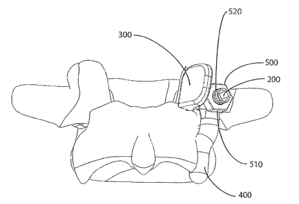
In Fig. 24, an enlarged head 500 is added to the fixation element 200 and is
tightened
down to force the prosthesis or prostheses into the bone to stabilize them.
The enlarged
5 head 500 shown in Fig. 24 has a hexagonal geometry on its external surface
that is shaped to
accept a driver (not shown) that is used to force an internal connection
feature 520 (e.g., a
screw thread) of the enlarged head 500 onto the connection feature 213 of the
fixation
element 200. In the case of the threaded embodiment of the connection feature
213, the
enlarged head 500 is provided with a threaded connection feature 520 and is
driven onto the
10 fixation element 200 by turning the enlarged head 500 and allowing the
threads to drive all
components of the implant between the enlarged head 500 and the first
resection surface 112
into the bone at or near the resection surface 112.
Fig. 25 is an isometric posterior view of the assembly of the fixation element
200,
the superior facet prosthesis 300, and the enlarged head 500 placed on the
first resection
15 surface 112. Fig. 26 is the same construct shown in Fig. 25, but with the
implants and the
vertebra 100 cut by a cross-sectioning plane 150 placed along an axis that
passes through the
center of the fixation element 200. The cross-section plan 150 shown cutting
through the
vertebra 100 and the implant in Fig. 26 is shown for visualization purposes to
illustrate,
using a cross-sectioned view, how the vertebra 100, fixation element 200,
superior facet
20 prosthesis 300 and the enlarged head 500 engage with each other. In actual
surgery, it is
highly unlikely that a surgeon would make a cut as illustrated by the cross-
section 150
shown in Fig. 26.
Fig. 27 is a view of the vertebra 100 and the implant wherein the cross-
section 150
shown in Fig. 26 is orientated such that the cross-section plane is facing the
viewer. In Fig.
27, the fixation element 200 is in the vertebra 100. The embodiment of the
fixation element
200 in Fig. 27 comprises a distal end 220 that is shaped to guide the fixation
element 200
into bone tissue, a bone stabilizing portion 210 adjacent and proximal to the
distal end, a
shaft portion 240 adjacent and proximal to the bone stabilizing portion 210, a
connection
feature 213 adjacent and proximal to the shaft portion 240, and a drive
feature 212.
The distal end 220 shown in Fig. 27 has a frustro-conical shape that allows
the
fixation element 200 to be driven or guided into the vertebra 100. The distal
end 220 could
be shaped in the form of a spade tip, trochar tip, or twist drill tip to
assist in the guidance of
FSI-06
CA 02539119 2006-03-15
WO 2005/030087 PCT/US2004/031488
21
the fixation element 200 in the vertebra 100. The fixation element 200 may
also have a
cutting flute (not shown) formed in the distal end 220 to help remove bone
tissue and
accommodate the guidance of the fixation element 200 in the vertebra 100. The
fixation
element 200 has a stabilizing portion 210 to help secure the fixation element
200 to the
vertebra 100. This stabilizing portion 210 is a structure that can be the
shape of various
features that are designed to anchor into bone such as threads, ribs, grooves,
slots, fms,
barbs, splines, bone ingrowth surfaces, roughened surfaces, or any geometric
feature that
helps to engage the fixation element 200 with the bone tissue to help
stabilize the fixation
element 200. In Fig. 27, the stabilizing portion 210 is shown as a unitary
continuous bone
thread 231. However, other types of threads such as multiple lead threads,
variable pitched
thread, non-uniform pitch thread, buttress thread, or other thread forms used
on bone screws
may be used. Because Fig. 27 is a cross-sectional view, the full length of the
cannulation
211 is seen passing from the distal end 220 of the fixation element 200 to the
proximal post
230 of the fixation element 200.
The drive feature 212 in the embodiment shown in Fig. 27 is an internal hex.
However, any shape of drive feature 212 that transmits the loads necessary to
drive the
fixation element 200 into the vertebra can be formed on the proximal post 230
of the
fixation element 200. The depth of the drive feature 212 formed in the
proximal post 230 of
the fixation element 200 is seen in the cross-sectional view of Fig. 27. The
drive feature 212
may be an internal drive feature such as the hex socleet shown in this
embodiment, or an
external drive feature with geometry on the periphery of the proximal post 230
of the
fixation element 200 that engages with a corresponding internal drive feature
on a driver
tool (not shown). In this embodiment the depth of the drive feature 212 is
slightly longer
than its cross-section is wide. This depth can be adjusted based on the
material properties of
the fixation element 200 and the drive tool (not shown).
The fixation element 200 is fabricated from biocompatible base materials that
allow
for the structural rigidity and strength needed. Examples of base materials
that the fixation
element 200 are made from include titanium, titanium alloys, cobalt-chrome
alloys, stainless
steel alloys, zirconium alloys, other biocompatible metal materials,
biocompatible ceramics,
biocompatible composites, and biocompatible polymers. The fixation element 200
may also
have surface materials formed on the base material that allow for material
properties specific
to a particular portion of the fixation element 200. For example, the bone
stabilization
FSI-06
CA 02539119 2006-03-15
WO 2005/030087 PCT/US2004/031488
22
portion 210 could be coated with materials that allow for improved bone
ingrowth into the
implant surface such as a hydroxylapatite, bioceramic, Bioglass°, or
other calcium
phosphate derived material. The tribological bearing properties of the
material in the areas
that the fixation element 200 interfaces with other artificial elements may be
improved by
applying surface hardening techniques to the material of the fixation element
200 in these
areas. Surface hardening techniques known in the materials science and
materials
engineering arts such as anodizing, ion implantation, and other techniques
could be applied
to these isolated areas.
A connection feature 213 is formed on the portion of the fixation element 200
that
protrudes from the first resection surface 112. This connection feature 213 is
designed to
connect the enlarged head 500 to the fixation element 200. In the embodiment
of the
connection feature 213 shown in Fig. 21, threads 260 are on the external
surface of this
proximal section of the fixation element 200. These threads 260 engage with
the threads on
the internal connection feature 520 (Fig. 27) of the enlarged head 500.
Although this
connection feature 213 in this embodiment is threaded, other mechanical
locking features
(not shown) capable of locking the fixation element 200 and the enlarged head
500 together,
such as press fit, taper fit, bonding fit by cement or glue, interference fit,
expansion fit and
mechanical interlocking fit such as a bayonet connection, can be used as the
connection
feature 213 (and a corresponding construction used on connection feature 520
of head 500).
Also shown in Fig. 27 is a cross-sectional view of an embodiment of the
superior
facet prosthesis 300. This embodiment of the superior facet prosthesis 300 has
a flange 323
that has an opening 324 that wraps around the fixation element 200. In the
assembled and
implanted configuration of this embodiment, the flange 323 is positioned such
that its bone
contacting surface 322 makes contact with the first resection surface 112.
Although not
shown in this embodiment, other embodiments of the superior facet prosthesis
300 have
structures (e.g., spikes) that protrude into the first resection surface 112
to help resist torsion
and other anatomic loads. Protruding from the flange 323 at a given angle a,
and a given
distance X from the opening 324, is an articulating component 320. The
articulating
component 320 has an articulating surface 321 that replicates the natural
articular surface of
the replaced facet. Once the surgeon assesses the anatomy of the superior
facet 43 that is
being replaced, a particular superior facet prosthesis 300 is selected that
has the angle a and
the distance X that best fits the anatomy of the level of vertebra, the left
or right side, and the
FSI-06
CA 02539119 2006-03-15
WO 2005/030087 PCT/US2004/031488
23
size of the patient's anatomy being replaced. Thus a kit containing various
sizes and shapes
of superior facet prostheses 300 are provided to the surgeon and the surgeon
selects the
superior facet prosthesis 300 that best suits the situation.
After the fixation element 200 and the superior facet prosthesis 300 are
selected and
placed, they are locked to the vertebra by the enlarged head 500. As shown in
Fig. 24, the
enlarged head 500 in this embodiment has an internal connection feature 520
and a
hexagonal shaped external drive feature 510 that is used to drive the enlarged
head 500 over
the fixation element 200 and against the superior facet prosthesis 300. The
specific shape of
the external drive feature 510 is dependent on the mating shape of the driver
(not shown).
Referring to Fig. 28, six different embodiments of the bone stabilization
portion 210
of the fixation element 200 are shown that are labeled A, B, C, D, E, and F.
The figure
shows a side view of each fixation element 200 embodiment and a cross-
sectional view of
each embodiment to the right of the respective side view. To the left of the
six embodiments
is a representative enlarged head 500. Embodiment A is the threaded fixation
element 200
embodiment shown in Figs. 26 and 27 and described above. Embodiments B through
E are
various designs of fixation elements with non-circular cross-sections.
Embodiment B is a
four rib cruciate design with four longitudinal fms configured to resist
torsion when the
fixation element 200 is in the vertebra 100. Embodiment C is an oval shaped
cross-section
design that is wider in the first direction than the second direction to
resist torsion. If the
dimension of the width in the first and second directions is equal, the cross-
section shape
becomes more of a circle and bone stabilization portion 210 becomes more of a
press-fit
peg. Embodiment D is a square cross-section design with four approximately
perpendicular
sides. The corners of the sides help to resist torsion. Embodiment E is a
triangular cross-
section design with three sides to resist torsion. Embodiment F is an anchor-
like design that
is driven into the vertebra, with the wire arches or barbs 290 being
compressed against the
host bone and applying a radial expansion force so as to lock the structure to
the bone.
Referring to Fig. 28A, six more different embodiments of the bone
stabilization
portion 210 of the fixation element 200 are show that are labeled G, H, J, I~,
L, and I. Fig.
28A shows a side view of each fixation element 200 embodiment and a cross-
sectional view
of each embodiment to the right of the respective side view. Each embodiment
has an
attached enlarged head 500. Embodiment G is similar to the threaded fixation
element 200
embodiment shown in Figs. 10, 1 l, 12 and 24 and described above. Embodiments
H
FSI-06
CA 02539119 2006-03-15
WO 2005/030087 PCT/US2004/031488
24
through K are various designs of fixation elements 200 with non-circular cross-
sections.
Embodiment H is a four rib cruciate design with four longitudinal fms 285
configured to
resist torsion when the fixation element 200 is in the vertebra 100.
Embodiment I is an oval
shaped cross-section design that is wider in the first direction 286 than the
second direction
287 to resist torsion. If the dimension of the width in the first direction
286 and second
direction 287 is equal, the cross-section shape becomes more of a circle and
bone
stabilization portion 210 becomes more of a press-~t peg. Embodiment J is a
square cross-
section design with four approximately perpendicular sides 288. The corners
289 of the
sides 288 help to resist torsion. Embodiment K is a triangular cross-section
design with
three sides 291 to resist torsion.
Embodiment L is an anchor-like design that is similar to Embodiment F in Fig.
28,
but with an attached enlarged head 500'. As embodiment L is driven into the
vertebra, wire
arches or barbs 290 are compressed and apply radial expansion force against
the wall of the
prepared bone and into the pedicle bone P resulting in a locking anchor.
Fig. 29 is an isometric view of a radially expanding fixation element 600. The
radially expanding fixation element 600 comprises two main elements, an
expansion sleeve
620 and a central element 610 that is inside of the expansion sleeve 620. The
radially
expanding fixation element 600 is placed into the vertebra and then the
central element 610
is pulled relative to the expansion sleeve 620 resulting in radial expansion
of the fixation
element 600. This is shown in Fig. 30. As the proximal post 630 of the central
element 610
is pulled axially along its longitudinal axis, and the expansion sleeve is
held axially in the
bone by compression fit, talons 621 on the expansion sleeve 620 are radially
expanded
outward by a mandrel 660 on the central element 610. The talons or forgers 621
provide
both torsional and axial stability to the radially expanding fixation element
600. This
provides a secure fixation element for fixation of the remaining components of
the implant.
Fig. 31 shows a cross-pin element 700 engaged with the fixation element 200 to
help
secure the fixation element 200 both torsionally and axially. The cross-pin
element 700 is
columnar in shape having a distal end 710, mid section 730 (with a length
along its
longitudinal axis that is longer than its transverse cross-sectional width),
and a proximal post
720. The distal end 710 is shaped to penetrate through bone tissue and into a
cross hole 280
formed in the fixation element 200. Instrumentation (not shown) is used to
align the cross-
pin element 700 with the cross-hole 280 by fixing to the drive feature 212 or
the cannulation
FSI-06
CA 02539119 2006-03-15
WO 2005/030087 PCT/US2004/031488
211 on the fixation element 200 and aligning the direction of insertion of the
cross-pin
element 700 with the cross-hole 280. Once the cross-pin element 700 is in
place in the bone
and through the fixation element 200, the torsional and axial stability of the
fixation element
200 is improved.
The various embodiments of the fixation element 200 described above and shown
in
Fig. 28 through Fig. 31 function in conjunction with the enlarged head 500 to
hold the
inferior facet prosthesis 400 and/or the superior facet prosthesis 300 to
their respective
resection surfaces. Various combinations of this modular implant will be
described below
and shown in Figs. 32 through 37. Although these figures show a fixation
element 200 and
10 enlarged head 500 as the means of securing the prostheses to the vertebra,
other clamping
means such as the screw fastener 17 (Fig. 10) may be used to mount the
prosthesis to the
bone. For example, the screw prostheses 17 shown in Figs. 10 through 12 passes
through
either the opening 324 (Fig. 22) in the superior facet prosthesis 300 or the
opening 410 (Fig.
23) in the inferior facet prosthesis 400 or through both of these openings
wherein the head of
15 the screw fastener 17 acts as the securing means pressing the inferior
facet prostheses 400
and the superior facet prosthesis 300 against their respective resection
surfaces.
Figs. 32 through 37 demonstrate different combinations of assemblies of the
facet
replacement prosthesis. The basic components of the prosthesis are the
fixation element
200, superior facet prosthesis 300, inferior facet prosthesis 400, and the
enlarged head 500.
20 However, as described above, a screw fastener 17 can replace the fixation
element 200 and
the enlarged head 500.
Referring to Fig. 32, three sequential layers of vertebra are shown, the top
vertebra
101 is above the middle vertebra 102 that is shown above the bottom vertebra
103. Portions
of some of the facets on the right side of the vertebrae are replaced by
prostheses. Looleing
25 at the facet joint between the top vertebra 101 and the middle vertebra
102, inferior facet
prosthesis 401 is articulating against superior facet prosthesis 302 to form
an artificial
unilateral joint. The inferior facet of the middle vertebra 102 is replaced by
inferior facet
prosthesis 402 and the superior facet of the bottom vertebra 103 is replaced
by superior facet
prosthesis 303. Thus, a second unilateral prosthetic joint is formed that is
also on the right
side and is located at the level between the middle vertebra 102 and the
bottom vertebra 103.
Fig. 32 demonstrates the difference in shape of the inferior facet prosthesis
401 that is
implanted around the fixation element 201 without a superior facet prosthesis
300 and an
FSI-06
CA 02539119 2006-03-15
WO 2005/030087 PCT/US2004/031488
26
inferior facet prosthesis 402 that is implanted around a fixation element 202
and over a
superior facet prosthesis 302. The opening 410 of the inferior facet
prosthesis 401 on the
top vertebra 101 in this assembly is offset more laterally than the opening
410 in the inferior
facet prosthesis 402 for the middle vertebra 102. This is because the fixation
element 201 is
implanted more laterally on the top vertebra 101 to preserve more of the
superior facet since
it is not replaced by a prosthesis at this level.
Referring to Fig. 33, the top vertebra 101 is left intact without resection of
the facets.
Portions of both the superior and inferior facets on the right side of the
middle vertebra 102
are replaced by superior facet prosthesis 302 and an inferior facet prosthesis
402. Only the
right superior facet of the bottom vertebra 103 is replaced (i.e., by a
superior facet prosthesis
303) in Fig. 33. Thus, a hemiplasty replacement results on the right facet
joint between the
top vertebra 101 and the middle vertebra 102 and a unilateral replacement
results between
the middle vertebra 102 and the bottom vertebra 103. This assembly shown in
Fig. 33
demonstrates how the superior facet prosthesis 302 can articulate against a
natural inferior
facet 6 or superior facet prosthesis 303 can articulate against an inferior
facet prosthesis 402.
Fig. 34 shows how an inferior facet prosthesis 401 can articulate against a
natural
superior facet 43, or a inferior facet prosthesis 402 can articulate against
superior facet
prosthesis 303. The right facet joint between the top vertebra 101 and the
middle vertebra
102 is a hemiplasty replacement with the inferior facet replaced by an
inferior facet
prosthesis 401. The right facet joint between the middle vertebra 102 and the
bottom
vertebra 103 is a unilateral replacement with the inferior facet replaced by
an inferior facet
prosthesis 402 and the superior facet of the bottom vertebra 103 replaced by a
superior facet
prosthesis 303.
Fig. 35 shows another example of how the superior facet prosthesis 303 can
articulate against a natural inferior facet 6 or superior facet prosthesis 302
can articulate
against an inferior facet prosthesis 401. In this assembly of the implant, the
right side
between the top vertebra 101 and the middle vertebra 102 is a unilateral
replacement and the
right side between the middle vertebra 102 and the bottom vertebra 103 is a
hemiplasty
replacement.
Fig. 36 shows another example of how an inferior facet prosthesis 402 can
articulate
against a natural superior facet 43, or an inferior facet prosthesis 401 can
articulate against
superior facet prosthesis 302. The right facet joint between the top vertebra
101 and the
FSI-06
CA 02539119 2006-03-15
WO 2005/030087 PCT/US2004/031488
27
middle vertebra 102 is an unilateral replacement with the inferior facet
replaced by an
inferior facet prosthesis 401 and the superior facet of the middle vertebra
102 replaced by a
superior facet prosthesis 302. The right facet joint between the middle
vertebra 102 and the
bottom vertebra 103 is a hemiplasty replacement with the inferior facet
replaced by an
inferior facet prosthesis 402.
The assembly of the implant shown in Fig. 37 demonstrates only one level, that
between the middle vertebra 102 and the bottom vertebra 103, being replaced on
the right
side.
Fig. 38 and Fig. 39 show two embodiments of the superior facet prosthesis. The
embodiment shown in Fig. 38 is curved superior facet prosthesis 305 with a
curved
articulating component 320 that has a curved articulating surface 321. This
curved
articulating surface 321 allows for a more distributed contact load between an
inferior facet
prosthesis 400 and the curved articulating surface 321. This allows slightly
more flexibility
in the position that the surgeon places the curved superior facet prosthesis
305 than the
superior facet prosthesis 300 previously described. The articulating surface
321 of the
superior facet prosthesis 300 previously described is relatively flat. The
articulating surface
321 of the curved superior facet prosthesis 305 is curved. Since the bearing
portion of the
inferior facet prosthesis 400 is columnar, the two prosthesis can be aligned
on a slight
mismatch and make more of an anatomic contact if the articulated surface is
curved as in
Fig.38.
Fig. 39 illustrates bone ingrowth feature 390 on the superior facet prosthesis
306.
This bone ingrowth feature can be any surface that allows bone to grow into
the implant
between the first resection 111 of the vertebra and the 322 bone-contacting
surface 321 of
the implant. Examples of bone ingrowth features 390 include porous coating of
beads or
meshes, electrochemically etched shapes and porous pads pressed onto the
implant surface
made from tantalum, titanium, cobalt chrome alloys or and other biocompatible
material
such as hydroxylapatite or calcium phosphate ceramics.
Fig. 40 shows an isometric view of an inferior facet prosthesis 400 formed in
the
general shape of a finger or talon. More particularly, inferior facet
prosthesis 400 is formed
with a flange 420 on its superior side shaped to either flt between the
superior facet
prosthesis 300 and the enlarged head 500, or between the first resection
surface 112 and the
enlarged head 500. The flange 420 has an opening 410 through it that is
dimensioned to
FSI-06
CA 02539119 2006-03-15
WO 2005/030087 PCT/US2004/031488
28
allow the inferior facet prosthesis 400 to fit over the proximal end 210 of
the fixation
element 200 and around the post of the fixation element 200. The inferior
facet prosthesis
400 also has an inferior portion 450 on the opposite side of the flange 420
that has a bone
apposition side 440 that is shaped to contact the surface of the resected bone
121 (Fig. 19)
and joint articulation side 430 that is shaped to articulate with a natural or
prosthetic superior
facet.
Fig. 41 shows an isometric view of an inferior facet prosthesis 400 also
formed in the
general shape of a finger or talon. Inferior facet prosthesis 400 is formed
with a superior
end 420 having an opening 410 that is dimensioned and shaped to accept the
fixation
element 200. The inferior facet prosthesis is generally columnar in shape,
having a curved
length designed to conform to the prepared anatomy of the vertebra 100. The
inferior facet
prosthesis 400 of Fig. 41 has an inferior portion 450, which is shown opposite
the superior
end 420, and slightly medially offset from the superior end 420. This medial
offset of the
opening 410 relative to the inferior portion 450 allows the inferior facet
prosthesis 400 to be
anchored to the bone by the fixation element 200 and secured to the bone by
the enlarged
head 500, or the superior facet prosthesis 300 in combination with the
enlarged head 500, at
an anatomical position that allows optimal bone fixation. The inferior facet
prosthesis
embodiment of Fig. 41 has a bone ingrowth surface 441 and an articulating
surface 430 on
its inferior end 450. In this embodiment, the bone ingrowth surface 441 is a
textured
structure that permits bone cells to grow into the implant surface. The shape
of the bone
ingrowth surface 441 can be a uniform textured surface as shown in Fig. 41, or
can be a
non-uniform randomized structure such as a open cell foam structure, a porous
beaded
structure, a wire mesh structure, an electrochemical etched structure, or
other bone ingrowth
structures known in the design of orthopedic implants. The bone ingrowth
surface is shaped
to mate with the inferior resected bone surface 121 such as shown in Fig. 19
and Fig 20.
Fig. 42 shows a posterior isometric view of an embodiment of the superior
facet
implant 300 that has an additional locking washer 800 to assist in stabilizing
the superior
facet implant to the first resection surface 112. The construction of the
implant assembly
shown in Fig. 42 is similar to that of the assembly shown in Fig. 25 with the
addition of the
locking washer 800 that is placed over and around the superior facet implant
300.
Fig. 43 shows the same implant of Fig. 42 with the enlarged head 500 locked
onto
the fixation element 200 and pushing the locking washer 800 against the
superior prosthesis
FSI-06
CA 02539119 2006-03-15
WO 2005/030087 PCT/US2004/031488
29
300 and into the bone tissue. This added bone penetration of the locking
washer 800 helps
to fix the superior prosthesis 300 such that the entire assembly is more
mechanically stable
with respect to the vertebra 100.
Fig. 43 shows a further step in the assembly of the implant construct
described in
Fig. 42. In Fig. 43, the locking washer 800 is secured over the fixation
element 200 and into
the bone tissue by the enlarged head 500. Although this embodiment of the
locking washer
800 is only shown with the superior facet prosthesis 300, the locking washer
800 can also be
used to mechanically secure the inferior facet prosthesis 400 and the
combination of the
inferior facet prosthesis 400 and the superior facet prosthesis 300. In the
embodiment of the
locking washer 800 shown in Fig. 42 and Fig. 43, the locking washer 800 is
placed over the
superior facet prosthesis 300. However, the locking washer 800 may be placed
under the
superior facet prosthesis 300 or under any other combination of inferior facet
prosthesis 400
and superior facet prosthesis 300, or between the superior facet prosthesis
300 and the
inferior facet prosthesis 400 to stabilize the implant construct.
Fig. 44 shows an isometric view of the locking washer 800. The locking washed
800
has an opening 810 in the body 805 that is dimensioned to fit over the
proximal post 230 of
the fixation element 200. The locking washer 800 also has an anti-rotation
feature 820 that
mates with either the superior facet prosthesis 300 or the inferior facet
prosthesis 400 or a
combination of both the inferior facet prosthesis 400 and the superior facet
prosthesis 400.
The anti-rotation feature 820 shown in this embodiment is a flat surface,
however, any
feature that would rotationally constrain the locking washer 800 to the other
components of
the implant (such as a tab, groove, taper or other geometric shape) can be
formed on the
washer as a anti-rotation feature 820. The locking washer 800 also has prongs
830 that pass
into the bone tissue of vertebra 100 to help stabilize the implant construct.
The prongs in
this embodiment of the locking washer 800 are elongated protrusions that taper
to a tissue
penetration tip 840. The prongs have sidewalls 850 that provide a surface to
resist torsion
once the locking washer 800 penetrates the bone tissue. The prongs 830 may
also be simple
spikes that are either symmetrical or nonsymmetrical in cross-section that
protrude from the
locking washer body 805. The shape and length of the locking washer prongs 830
is
dependent on how the locking washer is used. The prongs 830 of the locking
washer 800
that holds only one of the inferior facet prosthesis 400 or the superior facet
prosthesis 300 to
the vertebra 100 may be shorter than the prongs 830 of the locking washer 800
that holds
FSI-06
CA 02539119 2006-03-15
WO 2005/030087 PCT/US2004/031488
both the inferior facet prosthesis 400 and the superior facet prosthesis 300
to the vertebra
100.
Fig. 45 shows the superior facet prosthesis 300 and inferior facet prosthesis
400 held
to the vertebra 100 by adjunctive flexible fixation element 900 and secondary
flexible
fixation element 910. These flexible fixation elements 900 and/or 910 may be
made from
such constructs as suture, braided cable, wire, ribbon, and other constructs
that have longer
lengths than cross-sections and withstand larger loads in tension than in
compression. The
flexible fixation element 900 and/or 910 may be manufactured from
biocompatible metals,
alloys such as cobalt chrome alloys, titanium alloys, stainless steel alloys,
polymers,
10 bioabsorbale materials, composites, or other materials that are
biocompatible and can be
formed into a flexible element structure 900 and/or 910 such as those shown in
Fig. 45. The
adjunctive flexible element 900 shown in Fig. 45 is shown attached to and
securing the
elongated head 500. A flexible element attachment portion 580 (e.g., including
an opening)
mates the flexible element 900 to the elongated head. However, the adjunctive
flexible
15 fixation element 900 may attach to and add adjunctive fixation element 900
to the fixation
element 200, the superior facet prosthesis 300, the inferior facet prosthesis
400 or a
combination of the above listed elements of the prosthesis. A flexible
fixation attachment
portion 480 (e.g., including an opening) in the inferior facet prosthesis 400
allows the
secondary flexible fixation element 910 to secure the inferior facet
prostheses 400 to the
20 vertebra 100. The flexible fixation elements 900 and/or 910 may be secured
to the vertebra
100 by physically wrapping around anatomic features such as the posterior arch
35, the
spinous process 46, or transverse process 105 or a combination of these
anatomic features.
The flexible element 900 and secondary flexible element 910 may also be
secured to the
vertebra by bone anchors such as anchors designed to anchor flexible fixation
elements
25 (such as suture) to bone. Suture anchors such as threaded suture anchors,
barbed suture
anchors, toggle suture anchors or any other means of anchoring a flexible
fixation element to
bone may be used to anchor the flexible fixation element 900 or the secondary
flexible
fixation element 910 to the vertebra 100.
Fig. 46 is a dorsal view of a bilateral inferior facet prosthesis 1000. The
bilateral
30 inferior facet prosthesis 1000 is a one-piece inferior facet prosthesis
that has both a right
inferior side 1040 and a left inferior side 1020 connected by a stabilizing
bar 1010. Both the
right inferior side 1040 and the left inferior side 1020 are designed to fix
to the vertebra at
FSI-06