Note: Descriptions are shown in the official language in which they were submitted.
CA 02539743 2006-O1-10
Snowmobile Track Suspension
Field of the Invention
The invention relates to rear track suspensions for snowmobiles. More
particularly, the invention relates to a rear track suspension wherein the
front and rear
suspension arms interact to varying degrees as the suspension travels through
its full
range of motion. Even more particularly, the invention relates to rear track
suspension
wherein movement of both the front and rear suspension arms is dampened using
a
single resilient element.
Background of the Invention
Modem snowmobiles typically have two skis for supporting the front of the
machine and to provide steering and a rubber track for supporting the rear of
the
machine and to provide traction force. The rider is typically positioned
anywhere from
directly over the center of the track to over the front of the track, while
the engine is
located between the drive track and the skis, usually as low as possible.
A snowmobile is considered to be an off-road vehicle and as such it must be
able
to contend with many different riding environments. The terrain may change
from
smooth trails to large bumps and jumps. Snow conditions can vary from grippy
hard-
pack to bottomless powder, from smooth trails to rough and bumpy ones.
Accordingly,
modem snowmobiles are equipped with long travel suspensions at the front
(skis) as
well as at the rear (track). The rear track suspension is mounted to the
underside of the
snowmobile within a tunnel that partially encloses the track and suspension. A
seat for
the snowmobile rider is provided on top of the tunnel and running boards are
provided
on either side for supporting the rider's feet.
Existing snowmobile rear suspensions are quite similar. A rubber track is
driven
from the front by a set of cogged drivers. A set of slide rails enclosed
within the track
pushes the track onto the ground and provides a sliding surface for the track
and
mounting points for wheels and suspension arms. There are generally two sets
of
pivoting suspension arms connecting the rails to the tunnel, one positioned in
front of
1
CA 02539743 2006-O1-10
the other at similar angles to form a parallelogram. In most suspensions, both
arms are
biased downwards with two separate springs. The springs can be arranged in a
number
of ways to provide various motion ratios (i.e., spring compression versus
suspension
movement). Each spring is typically controlled by a hydraulic shock absorber
to allow
the suspension to release bump energy slower than it is absorbed and to
prevent un-
dampened oscillation.
A snowmobile's rear suspension must be able to perform the following functions
under all conditions: isolate the rider and the machine from the full bump
force; maintain
track contact with the ground by allowing the rails to articulate to some
degree; and,
allow the snowmobile to "lean back" upon acceleration to transfer weight to
the track.
In most current designs, bump absorption is obtained by using springs and
shocks which are mounted in various ways to provide the desired motion ratio.
A motion
ratio compares spring and shock compression with suspension compression. A
falling
rate motion ratio is one where the shock speed decreases as the suspension
compresses at a constant rate. This results in a soft and comfortable ride,
but has poor
resistance to bottoming over large bumps and upon landing after being
airborne. A
rising rate motion ratio is one in which the shock speed increases as the
suspension
compresses at a constant rate. This setup is typically found in sport
snowmobiles and
provides excellent control at high speeds and excellent bottoming protection.
Because the off-road environment is often unsmooth, the slide rails must be
able
to pitch forward and backward to some degree in order to maintain full track
contact with
the ground. If the arms and rails formed a solid parallelogram, this would not
be
possible. Instead, this function is typically accomplished by using a solid
mounting point
for only one of the arms (usually the front arm). The other (back) arm mounts
indirectly
to the rails using either a third smaller arm or some sort of telescoping
device. The
amount of rail pitch must be limited to eliminate excessive pitching of the
entire
machine. This is done in several different ways, usually by limiting the
rotation of the
third arm or limiting the amount of axial movement of the telescoping device.
Once the
limit is reached, the suspension is coupled, and the suspension geometry
approximates
a parallelogram. This forces both arms to compress at the same time. The
moment at
2
CA 02539743 2006-O1-10
which a limit is reached is sometimes referred to as the "coupling moment".
Most
suspensions are coupled in both directions (front to back and back to front),
but a few
are coupled only in one direction, allowing unrestricted movement of the front
arm or of
the rear arm.
A snowmobile suspension must also provide weight transfer. Because snow
provides limited traction, it is important to put as much of the vehicle
weight over the
track as possible during acceleration. This is typically accomplished by using
the track
tension during acceleration to actively pitch the rails, lifting the front of
the machine to
some degree. Upon acceleration, the top part of the track is in tension. A
force analysis
performed at the rear axle of the suspension typically shows a major component
pushing the rails forward and a minor component pulling the back of the rails
upward.
The major forward push on the rails is transferred to the front arm where,
because of its
angle, it pushes the centre of the machine upwards, increasing the downward
force on
the front of the rails. The minor component pulling up on the back of the
rails pulls the
rear of the machine downwards, decreasing the downward force on the back of
the
rails. The result is a snowmobile with less weight on its skis and more on its
track.
As mentioned above, in a typical snowmobile riding environment, bumps of all
sizes may be encountered. A certain amount of rail pitch is beneficial to
allow the track
to maintain better contact over the smaller bumps. In some situations,
however, the
amount of rail pitch must be limited. This is accomplished by several means,
usually
involving a stopper or a bumper of some sort. The movement of a shorter third
arm or a
telescoping device is limited by a rubber bumper or a similar device.
When the track suspension encounters a large bump at high speed, first the
front
arm compresses relative to the underside of the snowmobile. Without any
coupling
device, the front spring may be overcome by the large bump force and the front
arm
may bottom harshly. If the two arms become coupled at a certain point, both
front and
rear arms are forced to move together. This allows the bump to be absorbed by
both
front and rear springs, effectively increasing the amount of bump energy that
can be
absorbed using a given set of springs. It is also possible to simply use
stronger springs
on the front arm, but this results in a harsher ride.
3
CA 02539743 2006-O1-10
Another scenario in which coupling is desirable is in tail first landings. It
is not
uncommon for snowmobilers to launch the entire machine into the air, often
landing "tail
first". In this case, the rear arm in the suspension is prone to rapid
bottoming. In this
case, coupling also allows the impact to be absorbed by both suspension arms
and their
respective springs and shocks.
In most suspensions, coupling is provided by a set of bumpers or a by a set of
rods that are able to telescope to a certain extent. At the instant when these
suspensions couple, the overall spring force is instantly doubled as both
suspension
arms are forced to move and both springs are engaged. This is characterized by
a
harsh ride over "chatter bumps" (i.e., small to medium size evenly spaced
bumps that
force the coupling device to reach both its limits in rapid succession
repeatedly). This is
far less desirable than gradual coupling and a smooth increase of overall
spring force as
the suspension compresses.
There are several currently available rear suspension designs for snowmobiles.
United States patent application 10/698,980, filed October 31, 2003 by Imamura
et al. and published August 19, 2004. includes a quadrilateral linkage system
formed
between a vehicle body frame, a front torque arm assembly, a rear torque arm
assembly, and an extendable member. This suspension uses one coil-over spring
to
bias both suspension arms. The shock mounts to each arm a certain distance
from its
pivot so that as the suspension compresses, the shock also compresses. It is a
falling
rate design with a multi-rate spring that becomes progressively stiffer as it
is
compressed. The rear arm is mounted to the rails using a short, vertical arm.
The
device which limits the amount of rail pitch is the lower extendable member
linking both
arms together. The extendable member comprises a telescoping rod with
adjustable
limits.
United States Patent No. 6,390,219 filed May 14, 2001 by Vaisanen discloses a
snowmobile suspension that provides a substantially constant motion-ratio
(i.e. reduced
falling rate) over the entire suspension stroke of the suspension system. The
suspension system includes a suspension assembly that includes a lower arm
4
CA 02539743 2006-O1-10
assembly, a suspension arm, and a shock absorber. The lower arm assembly
pivotally
interconnects the lower portion of the suspension arm and the lower end of the
shock
absorber to the slide frame at a location relative to the chassis and within
the endless
track. The upper portion of the suspension arm and the upper end of the shock
absorber pivot independently from each other, and the upper portion of the
suspension
arm is positioned lower and forward of the upper end of the shock absorber.
The upper
end of the shock absorber is positioned relative to the chassis and within the
endless
track. The mounting positions defined by (i) the upper end of the suspension
arm, (ii)
the upper end of the shock absorber, (iii) the lower end of the suspension
arm, and (iv)
the lower end of the shock absorber cooperate to provide a substantially
constant
motion-ratio as the slide frame collapses toward the frame element. The rear
arm is
attached to the rails by an "upside down" third vertical arm.
United States Patent No. 6,234,264 filed November 24, 1998 by Boivin, et al.
discloses another snowmobile track suspension. The suspension disclosed by
Boivin et
al. is a long travel design. The front arm is mounted directly to the tunnel
and the front
shock is mounted in typical fashion. The front arm is mounted to the rails by
means of a
sliding pivot in a slot. The rear arm is mounted directly to the tunnel and
directly to the
rails by means of an adjustable pivot that allows for the necessary rail
pitch. The rear
shock is mounted in similar fashion to the front one.
While there are numerous rear suspension designs, these designs all have
several problems and disadvantages.
One problem relates to slide rail pitching. During acceleration, various
suspension forces result in less pressure on the skis. In the foregoing prior
art designs,
the arrangement of the suspension arms has an unstable geometry. Once the
rails
begin to pitch (either forward or backward), there is a decreasing amount of
resistance
to further pitch. The result is that once the rails begin to pitch upon
acceleration, they
tend to continue to do so until they reach a limit at full transfer at which
point the skis
are not in contact with the ground. Once the skis begin to lift, they tend to
"snap up",
only coming down once the amount of acceleration (throttle opening) decreases
by a
large amount. While a controllable amount of ski lift is desirable, too much
of it results in
5
CA 02539743 2006-O1-10
poor steering and cornering characteristics. Ideally, a rider should be able
to control
weight transfer more with his body movement than throttle opening.
Another problem exists in designs using a third vertical arm, such as that
disclosed by Imamura. As the rail begins to pitch the angle of the third arm
changes. A
force analysis typically reveals that further pitch becomes progressively
easier until a
hard limit is reached. This characteristic encourages rapid back and forth
pitching within
the predetermined limits.
Yet another problem relates to the spring and shock motion ratio. This ratio
describes the compression of the shock and/or spring in relation to the upward
movement of the suspension rails. As mentioned above, there are three general
variations: falling rate, linear, and rising rate. A falling rate suspension
has a
shock/spring ratio that falls as the suspension is compressed. This causes the
suspension to feel softer over large bumps, but can easily bottom out the
suspension
with large input forces. When a suspension bottoms out, a large "jolt" is fed
into the
chassis. The result is rider discomfort, potential loss of control, and very
high stress
levels on suspension components. A rising rate suspension gets more firm as
the
suspension compresses. This provides excellent bottoming resistance but also
results
in a firm (bumpy) ride over certain bumps. A constant ratio suspension falls
in the
middle of the other two, combing some traits of each.
Ideally, a suspension should combine the comfort of a falling rate design with
the
ability to handle large bumps of a rising rate design. Much effort has been
made to this
effect. Falling rate suspensions are fitted with multiple springs with
different rates in an
effort to prevent bottoming. Many shocks are designed so that there is no
effective
dampening in mid-stroke to allow more comfort over small, rapid stutter bumps.
While
somewhat effective, these approaches involve compromise between comfort and
control.
A need therefore exists for an improved snowmobile rear suspension.
Consequently, it is an object of the present invention to obviate or mitigate
at least some
of the above mentioned disadvantages.
6
CA 02539743 2006-O1-10
Summary of the Invention
According to the present invention, there is provided a track suspension for a
snowmobile comprising: a rear arm having an upper end pivotally attachable to
an
underside of the snowmobile at an upper rear arm pivot, a rear arm crank
extending
from the rear arm at the upper end thereof, the rear arm having a lower end
pivotally
connected to a slide rail at a rear slide rail pivot; a front arm having an
upper end
pivotally attachable to the underside of the snowmobile at an upper front arm
pivot, a
front arm crank extending from the front arm at the upper end thereof; a front
linkage
having an anterior end pivotally connected to the front arm crank and having a
posterior
end pivotally attached to the rear arm crank at a posterior linkage pivot;
and, a resilient
element having an anterior end pivotally attached to the front linkage, the
resilient
element operable to resist pivoting movement of the rear arm about the upper
rear arm
pivot in response to movement of the rear slide rail pivot towards the
underside of the
snowmobile.
The front linkage may be pivotally connected to the front arm crank by means
of
a front rocker. The front rocker may be pivotally attached to the front arm
crank at a
front rocker pivot and pivotally attached to the front linkage at an anterior
linkage pivot.
The anterior linkage pivot may be rearward of the front rocker pivot.
The resilient element may comprise a fluid filled shock absorber in
combination
with a co-axially mounted coil spring. Persons skilled in the art will
recognize that other
types of resilient elements can be provided to achieve a similar effect. The
resilient
element may have a posterior end pivotally attached to an upper end of a rear
rocker
having a lower end that is pivotally attached to a rear linkage at a rear
linkage pivot.
The rear rocker may be pivotally attached to the rear arm at a rear rocker
pivot located
between the upper and lower ends of the rear rocker. A lower end of the front
arm may
be pivotally attached to the rear linkage. The front arm may have an outwardly
extending dog between its upper and lower ends that is pivotally attached to a
lower
end of a rail rocker having an upper end pivotally attached to the slide rail
at a front slide
rail pivot. In this case, the lower end of the rear arm may be connected to
the slide rail
by direct attachment to the rear slide rail pivot. Alternatively, the front
arm may be
7
CA 02539743 2006-O1-10
pivotally attached to the slide rail at the front slide rail pivot at a
location between the
upper and lower ends of the front arm. The lower end of the rear arm may then
be
connected to the slide rail by means of an upright rocker having an upper end
pivotally
attached to the lower end of the rear arm and having a lower end pivotally
attached to
the slide rail at the rear slide rail pivot.
In operation, compression of the rear slide pivot towards the underside of the
snowmobile causes the rear arm to rotate about the upper rear arm pivot,
thereby
causing the rear arm crank to pull upon the front linkage against the bias of
the resilient
element connected thereto. This action in turn causes the front rocker to pull
at
substantially a right angle to the front arm crank, thereby causing a rotation
of the front
arm in a direction corresponding to the rotation of the rear arm. This
rotation is resisted
by the rear linkage, which pushes against the rear rocker and thereby further
compresses the resilient element from the posterior thereof.
The suspension of the present invention advantageously permits dampening of
both the front and rear suspension arms using a single resilient element while
still
providing the desired balance between ride cushioning and performance
characteristics.
The suspension provides the desired degree of rider weight and balance control
during
acceleration without excessive rail pitching while at the same time providing
a smooth
ride over chatter bumps without bottoming out during tail-first landings. The
suspension
advantageously exhibits a U-shaped motion ratio profile during compression. In
other
words, the suspension combines the advantages of falling rate, constant rate
and rising
rate designs during various stages of compression to provide the desired ride
and
handling characteristics.
Brief Description of the Drawings
Having summarized the invention, preferred embodiments thereof will now be
described with reference to the accompanying figures, in which:
Fig. 1 is a side view of a snowmobile having a track suspension of the present
invention mounted thereto;
Fig. 2 is a perspective view of the track suspension;
8
CA 02539743 2006-O1-10
Fig. 3 is a side cross-sectional view of the track suspension while traveling
over a
level surface;
Fig. 4a is a side cross-sectional view of the track suspension during full
compression;
Fig. 4b is a side cross-sectional view of the track suspension during full
extension;
Fig. 5 is a side cross-sectional view of the track suspension with front arm
compression, for example when the snowmobile first encounters a terrain
obstacle;
Fig. 6 is a side cross-sectional view of the track suspension with rear arm
compression, for example when the snowmobile is leaving a terrain obstacle;
Fig. 7 is a plot of motion ratio vs. suspension compression for the track
suspension with a selected set of linkage length adjustments and spring
compressions;
and,
Fig. 8 is a side cross-sectional view of another track suspension according to
the
present invention.
Detailed Description of Preferred Embodiments
Referring to Fig. 1, a snowmobile 1 is shown generally with a pair of front
skis 2,
a seat 3 for supporting a rider 4 and a rear track 5. The rear track 5 is
driven by a front
drive pulley 6 and supported by a track suspension 7 according to the present
invention.
The track suspension 7 is mounted to the underside of the snowmobile 1 beneath
the
seat 3 within a tunnel that partially encloses the track 5, drive pulley 6 and
suspension
7. A pair of running boards (which have been omitted to better show the
invention) for
supporting the rider's feet are provided on either side of the tunnel. The
drive pulley 6
shown in Fig. 1 rotates in a counterclockwise direction. During throttle-
induced
acceleration of the snowmobile 1, the tension of the track 5 increases between
the drive
pulley 6, upper idler 8 and lower idler 9. The increased track tension causes
the
suspension to compress, particularly at the rear, and the lower idler 9 to
move toward
the underside of the snowmobile. This in turn causes the skis 2 to pitch
upwardly,
9
CA 02539743 2006-O1-10
reducing frictional drag at the front of the snowmobile 1 and desirably
increasing the
rate of acceleration of the snowmobile 1.
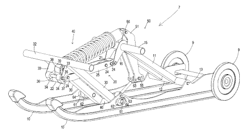
The various components of the track suspension 7 will now be further described
with reference to Figs. 2 - 4. A pair of slide rails 10 is provided on the
underside of the
suspension 7 and the track 5 (not shown in Figs. 2 - 4) passes under the slide
rail 10
and over the lower idlers 9 at the rear of the suspension. The suspension 7
comprises
a pair of rear arms 11, each rear arm 11 having an upper end and a lower end.
The
lower end of each rear arm 11 is attached to a lower rear pivot shaft 12,
which in turn
connects the lower ends to the slide rails 11 at a rear slide rail pivot 13.
The underside
of the snowmobile is represented by the dashed line U and the distance between
the
rear slide rail pivot 13 and U is represented by A. The upper end of each rear
arm 11 is
pivotally attached to the underside of the snowmobile at an upper rear arm
pivot 14 by
means of an upper rear pivot axle 15. A rear arm crank 16 extends forwardly
and
downwardly from the upper end of each rear arm 11 and is pivotally attached to
the
posterior end of a front linkage 20. The front linkage 20 is adjustable in
length and
comprises a rear linkage extension 21 and a front linkage extension 22
provided for that
purpose. Each linkage extension 21, 22 comprises a pair of slotted holes 23
and the
position of each linkage extension is adjustable by sliding movement relative
to
connecting bolts 24 passing through the slotted holes 24 and securing a pair
of opposed
side plates 25 to either side of each linkage extension.
The suspension 7 further comprises a pair of front arms 30, each having an
upper end and a lower end. The upper end of each front arm 30 is pivotally
attached to
the underside of the snowmobile at an upper front arm pivot 31 by means of an
upper
front pivot axle 32. A front arm crank 33 extends forwardly and downwardly
from each
front arm 30. The anterior end of the front linkage 20 is pivotally connected
to each
front arm crank 33 by means of a pair of front rockers 34 each having an upper
end that
is pivotally attached to its respective front arm crank 33 at a rocker pivot
35. The rocker
pivot 35 of each front rocker 34 is also connected to a front rocker shaft 36
located
between the front rockers 34. The lower end of each front rocker 34 is
pivotally
attached to the front linkage extension 22 of the front linkage 20 at an
anterior linkage
CA 02539743 2006-O1-10
pivot 37 that is below the rocker pivot 35. A front linkage portion 38 extends
upwardly
from each side plate 25 of the front linkage 20. Each front linkage portion 38
is located
between the anterior and posterior ends of the front linkage 20 and is
pivotally attached
to a resilient element 40 at a shock pivot 39.
The resilient element 40 comprises a fluid-filled shock 41 and a co-axial
externally mounted coil spring 42. The shock 41 and spring 42 co-operate to
provide a
bias against both the anterior and posterior ends of the resilient element 40
while at the
same time dampening suspension oscillation. Both the amount of bias and degree
of
dampening can be adjusted through manipulation of the spring 41 and shock 42,
respectively. The anterior end of the resilient element 40 is lower than the
posterior end
and, as a result, a component of the bias is directly downwardly on to the
anterior end of
the front linkage 16. This urges the anterior linkage pivot 37 to rotate about
the rocker
pivot 35 in response to movement of the suspension 7 and thereby changes the
angle
between the front rocker 34 and the front arm crank 33 in a manner as will be
more
thoroughly described hereinafter.
Although during normal operation the length of the front linkage 20 is fixed,
it can
also be adjusted by the rider to select a desired set of suspension dynamics
in response
to either riding conditions or performance objectives. Adjustment of the
length of the
front linkage 20 can be effected from either end thereof. Adjustment of the
length from
the posterior end can be used to select a desired angle between the front
linkage 20
and the rear arm cranks 16. Adjustment of the length from the anterior end can
be used
to select a desired angle between the front rockers 34 and the front arm
cranks 33.
Both ends of the linkage may be adjusted at the same time or they may be
adjusted
separately. Adjustment of the length of the front linkage 20 may also be used
to select
a desired downward angle of the resilient element 40, thereby effecting the
amount of
downward bias provided to the anterior linkage pivot 37.
The posterior end of the resilient element 34 is pivotally attached to the
upper
end of a rear rocker 50 at a posterior shock pivot 56. The rear rocker 50
comprises a
pair of opposed rear rocker plates 51 located to either side of the posterior
end of the
resilient element 40. Each rear rocker plate 51 is pivotally attached to its
respective
11
CA 02539743 2006-O1-10
rear arm 11 at a rear rocker pivot 52 located rearward of the upper rear arm
pivot 14
and between the upper and lower ends of the rear rocker 50. The lower end of
the rear
rocker 50 comprises a plurality of spaced apart adjustment holes 53 located in
each
rear rocker plate 51. A rear linkage 54 has an upper end that is pivotally
attached to the
rear rocker 50 at a rear linkage pivot 55 passing through a selected pair of
adjustment
holes 53. By selecting a different pair of adjustment holes 53 for the
location of the rear
linkage pivot 55, the angle between the rear linkage 54 and the rear rocker 50
can be
adjusted, thereby changing the moment angle and the amount of downward bias
provided to the rear linkage 54 from the posterior end of the resilient
element 40.
The rear linkage 54 has a lower end that is pivotally attached to a lower
front arm
connecting plate 60 that is fixedly attached to the lower end of each front
arm 30.
Between the upper and lower ends of each front arm 30 is provided an outwardly
extending dog 61 that is pivotally attached to the lower end of a rail rocker
62. The
upper end of each rail rocker 62 is pivotally attached to its respective slide
rail 10 at a
front slide rail pivot 63. The dog 61 is permitted to orbit arcuately about
the front slide
rail pivot 63 between first and second pitching constraints and extends
through a
substantially U-shaped slot 64 in the side rail 10. The first and second
pitching
constraints roughly correspond to the ends of the slot, although the dog 61
need not
necessarily engage the ends of the slot 64 to encounter the pitching
constraints.
Preferably, the pitching constraints are encountered in a gradual manner due
to a
progressively increasing force provided by the resilient member 40 as the dog
61
approaches each end of the slot 64. This preferred gradual approach to the
first and
second pitching constraints results in a much smoother ride than is provided
in prior art
suspensions that rely upon "hard coupling", or physical interaction between
parts at pre
determined motion limits.
The rear linkage 54 is adjustable in length and comprises a threaded
turnbuckle.
Adjustment of the length of the rear linkage 54 can be used to change its
angle with
respect to the front arms 30 and to thereby pre-set a desired height of the
rear of the
snowmobile. Adjustment of the rear linkage 54 can be made to accommodate
selection
of a different pair of adjustment holes 53.
12
CA 02539743 2006-O1-10
Referring to Figs. 5 and 6, the pitching action of the suspension in response
to a
terrain obstacle will now be discussed.
Turning specifically to Fig. 5, when a terrain obstacle is first encountered
by the
track, the front part of the slide rails 10 pitch upwardly to move over the
obstacle and
the front slide rail pivot 63 moves towards the underside of the snowmobile.
This
causes the dog 61 to move rearwardly in relation to the slot 64 as it rotates
about front
slide rail pivot 63 and approaches the first pitching constraint. The lower
end of the
front arm 30 then pushes against the rear linkage 54, thereby causing the rear
rocker 50
to rotate counter-clockwise about the rear rocker pivot 52 and compressing the
posterior
end of the resilient element 40. As the front of the slide rail 10 moves
upwardly, the rear
of the slide rail moves downwardly relative to the underside of the
snowmobile, as
represented by dashed line U. This in turn causes the distance between the
rear slide
rail pivot 13 and the underside of the snowmobile U, as represented by A', to
increase.
Much of the counter-clockwise rotational movement of the front arm 30 about
the upper
front arm pivot 31 is absorbed by the arcuate movement of the dog 61 about the
front
slide rail pivot 63 and by clockwise rotational movement of the front rocker
34 about the
front rocker pivot 35. As the first pitching constraint is approached, the
front rocker 34 is
nearly perpendicular to the front linkage 20 and rotational movement of the
front arm 30
pushes mostly downwardly on the front linkage, which causes very little
compression of
the resilient element 40. Contemporaneously, the rail rocker 62 approaches
being
parallel with the front arm 30. By virtue of the selected geometry, further
upward
pitching of the slide rails 10 causes a strong rearward force component to be
applied to
the slide rails and a corresponding tendency for the rear arm 11 to rotate
counter-
clockwise about the upper rear arm pivot 14. The distance A' therefore
approaches a
maximum as the first pitching constraint is approached. Further pitching of
the rails
beyond the first pitching constraint results in suspension compression as the
distance A'
decreases. The front of the slide rails 10 are therefore permitted to pitch
within a
window described by the difference between A and A' before gradually
approaching a
first pitching constraint beyond which the transition to suspension
compression begins.
13
CA 02539743 2006-O1-10
Turning now to Fig. 6, as the terrain obstacle passes to the rear of the
suspension 7, the rear slide rail pivot 13 moves upwardly towards the
underside U and
the distance A" decreases. This causes the rear arm 11 to rotate counter-
clockwise
about the upper rear arm pivot 14, causing the rear arm crank 16 to pull upon
the front
linkage 20. This causes the front rocker 34 to be drawn from a position that
is
substantially perpendicular to the front linkage 20 (as shown in Fig. 5) to a
position that
approaches being parallel with the front linkage 20. Contemporaneously, the
dog 61
orbits clockwise about the front slide rail pivot 63 and moves forward toward
the front of
the slot 64. Relatively little compression of the resilient element 40 occurs
as the front
rocker 34 changes position. However, as the front rocker 34 approaches the
parallel
position and the dog 61 approaches the second pitching constraint, further
rotation of
the rear arm 11 causes the linkage to pull strongly on the spring and causes
the front
rocker to act strongly on the front arm crank 33. The suspension then begins
to
compresses and both the front and rear arms 30, 11 begin to move. The rear of
the
slide rails 10 are therefore permitted to pitch within a window described by
the
difference between A and A" before gradually approaching a second pitching
constraint
beyond which the transition to suspension compression begins.
During compression of the rear of the slide rails beyond the second motion
constraint, such as is encountered during a tail first landing, the counter-
clockwise
rotation of the rear arm 11 causes the rear arm crank 16 to pull strongly
against the
anterior end of the resilient element 40 by means of the front linkage 20. The
front
rocker 34 is nearly parallel to the front linkage 20, so further compression
of the rear
arm 11 causes the front rocker 34 to pull strongly on the front arm crank 33,
forcing the
front arm 30 to rotate counter-clockwise. This action causes the front arm 30
to push
strongly against the rear linkage 54 and ultimately the posterior end of the
resilient
element 40 through the rear rocker 50. This bolsters compression of the
resilient
element 40 by the rotational action of the rear arm 11 and causes both arms to
contribute in resisting further rear suspension compression. This co-operative
action is
particularly useful in preventing "bottoming out" of the suspension upon a
tail-first
landing.
14
CA 02539743 2006-O1-10
Returning now to Figs 4a and 4b and referring additionally to Fig. 7, the
shock
speed and motion ratio during various phases of suspension compression is
illustrated.
Data was obtained by modeling motion ratio as a function of the distance
between the
rear slide rail pivot 13 and the underside of the snowmobile U, with 0 mm
representing
full compression (as shown in Fig. 4a) and 320 mm representing full extension
(as
shown in Fig. 4b). Starting from the vertical line representing the normal
riding position
shown in Fig. 3 (i.e. normal suspension compression of about 100 mm while
traveling
over level terrain), when a jump is made and the snowmobile becomes airborne
the
suspension begins to extend and we travel along the ordinate axis left of the
vertical
line. The motion ratio increases and the suspension therefore exhibits a
rising rate
behaviour. Upon landing, the suspension compresses and exhibits an initial
falling rate
behaviour where shock speed is resisted by progressively less force. This
provides a
cushioned landing. Once the suspension is somewhat compressed we move along
the
ordinate axis right of the vertical line and the motion ratio is constant
rate. As the
suspension becomes significantly compressed it begins to exhibit a rising rate
behaviour. The exponential increase in force as full compression is approached
is
particularly useful in preventing "bottoming out" of the suspension during
landing.
Referring again to Fig. 1, throttle-induced acceleration of the snowmobile 1
causes the tension of the track 5 to increase, resulting in suspension
compression that
moves the lower idler 9 towards the underside of the snowmobile and causes the
skis 2
to pitch upwardly. Although upward pitching of the skis 2 desirably results in
increased
acceleration due to reduced frictional drag, too much pitching causes
"twitchy"
performance under throttle and a potential loss of steering control during
acceleration.
It is therefore further desirable to limit ski pitch during acceleration,
preferably in a
gradual manner to prevent jarring movements as are encountered in prior art
suspensions due to physical interaction between parts and in order to provide
sufficient
feedback to the driver when approaching excessive throttle-induced ski pitch.
The
gradual approach to the second pitching constraint provided by the present
invention
advantageously provides this gradual feedback. Upon further acceleration past
the
second pitching constraint the suspension compresses toward the underside of
the
CA 02539743 2006-O1-10
snowmobile, particularly at the rear, and the suspension moves rightward from
the
vertical line through the constant rate region and into the rising rate
region. The rising
rate region provides a rapidly increasing resistance to further compression of
the
suspension, further acting to gradually limit ski pitch.
Referring to Fig. 8, an alternative embodiment of the invention is shown. In
this
embodiment, like numerals will be used to describe like features to those in
the
previously described embodiment. The rear arms 11 are pivotally connected to
the rear
slide rail pivot 13 by means of an upright rocker 80 having an upper end
attached to the
lower rear pivot shaft (not shown in Fig. 8), which is in turn attached to the
lower end of
the rear arms 11. The lower end of each upright rocker 80 is pivotally
attached to its
respective slide rail 10 at the rear slide rail pivot 13. In this embodiment,
the dog 61 of
each front arm 30 is pivotally attached directly to the front slide rail pivot
63, obviating
the need for the rail rocker. This embodiment functions in most respects
similar to the
previously described embodiment with the potential for certain manufacturing
and
maintenance advantages.
The front and rear linkages are described as being adjustable in length to
permit
adjustment of the suspension 7 by the rider for a preferred riding style or in
response to
riding conditions. The invention functions equally well without this
adjustability and the
variable length linkages may be replaced by fixed length linkages.
The foregoing describes preferred embodiments of the invention and other
features and embodiments of the invention will be evident to persons skilled
in the art.
The following claims are to be construed broadly with reference to the
foregoing and are
intended by the inventor to include other variations and sub-combinations that
are not
explicitly claimed.
16