Note: Descriptions are shown in the official language in which they were submitted.
CA 02539856 2006-03-16
= 256/099
Patent
FUME TREATMENT METHOD AND APPARATUS USING ULTRAVIOLET
LIGHT TO DEGRADE CONTAMINANTS
SPECIFICATION
Field of the Invention
The present invention relates to exhaust systems that withdraw fumes from
a conditioned space and release at least partly cleaned air to the ambient
atmosphere using ultraviolet light to reduce the contamination level.
Background of the Invention
Exhaust hoods are used to remove air contaminants close to the source of
generation located in a conditioned space. For example, one type of exhaust
hoods, kitchen range hoods, creates suction zones directly above ranges,
fryers, or
other sources of air contamination. The exhaust stream from such applications
often contain large quantities of particulates, particularly hydrocarbons such
as oil
droplets.
Organic substances in the form of vapours or particles can also be formed
by many production processes within various industries. For example, they can
be generated by preparation and use of lacquer and paint, cereal and
feedstuff,
metal and plastic, tar and asphalt, tanneries, incinerating plants, bio-gas
plants,
agriculture, and many food preparation processes.
WP.16946.1
l
CA 02539856 2006-03-16
256/099
Patent
Because of concerns about the environment and worker health, there is a
great need for economically attractive mechanisms for removing organic
substances from air streams. Air purification is frequently performed by
filtering
the contaminated air in, for example, grease filters and carbon filters.
Mechanical
filters, however, are only efficient in removing particles greater than about
5
microns. Furthermore, filters cannot guarantee fulfillment of high hygienic
requirements.
One technology that has been used for degrading organic particulates in
effluent streams is the addition of ozone to the effluent stream. This can be
accomplished by irradiating with ultraviolet light or using a corona
discharge. A
negative side effect of using corona discharge is the creation of NOR.
One example of an application of ultraviolet light to the purification of an
effluent stream is described in U.S. Patent. No. 6,179,969 to Larson. In the
embodiment described, contaminated air flows into a chamber and is diluted
with
ambient air to cool it and add oxygen to the air stream. The effluent stream
is
then irradiated with ultraviolet light and then ejected to the ambient. The
system
may include a filter for removing larger particles before introduction of the
effluent stream into the dilution section. Cooling of the stream causes
condensation of water and certain organic vapors. The oxygen injected in the
2o dilution process is used in the creation of ozone when the air is
irradiated with the
ultraviolet right. Certain organic substances are oxidized by the ozone in a
so-
2
CA 02539856 2006-03-16
256/099
Patent
called cold combustion and are thereby transformed into carbon dioxide, but
many
organic molecules can not be oxidized in this way. The ultraviolet light,
however,
also splits many of the organic molecules, making them more susceptible to
oxidation by ozone. The specification teaches that the oxidation process is
not
instantaneous and, therefore, the effluent stream must be exposed to the
ultraviolet
source for a substantial period of time before being ejected into the
atmosphere-
Another device that relies on ultraviolet radiation is shown in Japanese
Application No. 08019379, published 22.07.97. The document describes a range
hood with a self-cleaning function. A light coating of catalyst is formed on
filters
irradiated by a bank of ultraviolet lamps located in front of an exhaust
aperture.
Effluent streams passing the catalyst and lamps are oxidized and decompassed
by
contact with the catalyst and exposure to the light and ozone created by the
light.
Many patents have issued that describe similar systems employing
photocatalysts.
One of the problems inherent in any system in which ozone, or any other
agent, is relied upon for the treatment of an effluent stream, is insuring a
uniform
dwell-time or residence-time of every part of the effluent stream. Short
circuiting
by some of the effluent stream is a problem, since the flow moving from a
narrow
high velocity stream to a large-diameter slow moving stream must give up
energy
by generating energetic subflows. These can randomly crisscross a chamber
causing some of the flow to short-circuit the chamber. A large number of
baffles
can be used to spread the flow, but doing so requires a high pressure drop and
the
3
CA 02539856 2006-03-16
256/099
patent
baffle elements interfere with the transmission of ultraviolet light to all
parts of
the treatment volume.
Sumrnarv of the Invention
An ultraviolet exposure chamber contains a mechanism to generate a
stable flow effect inside the chamber to increase the minimum dwell time of
each
volumetric unit of air entering the chamber. The chamber is designed to use
momentum effects of the air to force the air to take a circuitous path through
the
chamber without the introduction of baffles or duct sections that would block
lo ultraviolet light from centrally-mounted light sources.
In an exemplary embodiment, lamps are located across a central part of a
plenum-type chamber and air is added via opposing nozzles located at opposite
sides of a lower end of the chamber. The nozzles are offset so that a swirl
flow
pattern is generated. Thus, the flow is routed in a long swirling path through
the
chamber while being continuously exposed to the ultraviolet light. Since
baffles
are not required to route the flow along the long path, no light blocking
effect is
suffered. This permits a smaller set of lamps to be used to expose the flow.
In another embodiment, the flow is introduced in such a manner that it is
forced to swirl and take a helical path through the chamber. The light sources
may be located in the center of the swirl effect, minimizing their contact
with
suspended particles because of the resulting radial density gradient. The
swirl has
4
CA 02539856 2010-06-03
the secondary effect of causing particles to separate onto an exterior wall,
which may be coated with
photocatalyst.
In yet another exemplary embodiment, flow through a chamber enters after being
conditioned to minimize turbulent energy and its generation through shear. A
low shear, possibly
laminar, flow is introduced at one end of the chamber. Because of the low
level (or absence) of
turbulence, each unit volume of air dwells in the chamber for a minimum
interval of time. Such a
flow can be generated using settling screens and flow straighteners, for
example. This type of
geometry, however, may not be preferred due to cost considerations and
manufacturing complexity.
Some of the embodiments, and others not described, may exploit the wall-flow
(Coanda)
effect to help insure minimal diffusion of mean flow energy into turbulent
eddies. If the flow is very
turbulent (large scale turbulence up to the length-scale of the flow chamber)
then substantial
portions of the flow can short-circuit the chamber. One way to create such a
wall-flow is by
injecting air into a chamber along a bounding wall section. The flow may
follow the wall for some
distance and may traverse the chamber according to various patterns depending
on the design. The
energy of a high velocity injected stream is not lost quickly to turbulence
energy because the flow's
dispersal and diminution of velocity are delayed.
Accordingly, in one aspect, the present invention resides in a flow treatment
apparatus,
comprising: a flow vessel with an inlet and an outlet; an ultraviolet light
source in said flow
vessel; said flow vessel being configured to generate a flow therethrough that
provides a
substantially constant residence time therein for all fractions of a flow
entering said flow vessel
without blocking light from said ultraviolet light source to permit said
ultraviolet light source to
irradiate said flow in said flow vessel; said flow vessel having a cylindrical
interior with a
longitudinal axis; said inlet being arranged to inject said flow at a tangent
to a curved wall of
said flow vessel; the inlet being positioned remotely from the outlet and
spaced apart from the
outlet along the longitudinal axis such that any fluid flowing into the flow
vessel through the
5
CA 02539856 2010-06-03
inlet must traverse a substantial portion of a longitudinal dimension of the
flow vessel to reach
the outlet; the ultraviolet light source being located at a longitudinal axis
of the flow vessel.
In another aspect, the present invention resides in an ultraviolet treatment
device,
comprising: a kitchen exhaust hood with a plenum attached thereto and in flow
communication
with an exhaust stream from said hood; said exhaust hood having a recess; said
plenum
containing at least one ultraviolet light source; said plenum having a volume
at least as great as
an interior volume of said recess; said plenum being configured to generate a
flow therethrough
that takes at least one turn, said flow being exposed to said light during a
majority fraction of a
residence time in said plenum; wherein said plenum has two inlets connecting
said recess to an
interior thereof, said inlets being arranged to generate a circulating flow in
said plenum;
wherein said inlets are opposed nozzles.
5a
CA 02539856 2006-03-16
2561099
Patent
While the invention will now be described in connection with certain
preferred embodiments and examples and in reference to the appended figures,
the
described embodiments are not intended to limit the invention to these
particular
embodiments. On the contrary, it is intended to cover all alternatives,
modifications, and equivalents as may be included within the scope of the
invention as defined by the appended claims. Thus, the following description
and
examples of the preferred embodiments of the invention are only intended to
illustrate the practice of the present invention. The particular embodiments
are
shown by way of example and for purposes of illustrative discussion of the
preferred embodiments of the present invention.
The particular embodiments are presented in the cause of providing what
is believed to be the most useful and readily understood description of the
principles and conceptual aspects of the invention. In this regard, no attempt
is
made to show structural details of the invention in more detail than is
necessary
for a fundamental understanding of the invention. The description, taken with
the
drawings, makes it apparent to those skilled in the art how the several forms
of the
invention may be embodied in practice.
Brief Description of-the Drawings
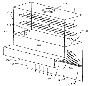
Fig. I is an illustration of an effluent gas treatment device attached to a
back-shelf style of range hood according to an embodiment of the invention.
6
CA 02539856 2006-03-16
256!099
Patent
Fig. 2 is an illustration of the flow pattern generated by the effluent gas
treatment device of Fig. 1.
Fig. 3 is a partial ghost view,of a first swirling flow-type effluent
treatment chamber according to an embodiment of the invention.
Fig. 4 is a partial cutaway view of second swirling flow-type effluent
treatment chamber according to another embodiment of the invention.
Fig. 5 is a partially-ghosted side view of a flow-settling chamber with
ultraviolet light sources for treatment of effluent streams according to yet
another
embodiment of the invention.
Fig. 6 is a partially ghosted side view of a treatment chamber relying on a
Coanda effect to generate a circuitous stream.
Detailed Description of the Illustrated Embodimmts
Referring to Fig. 1, exhaust fumes are drawn into an exhaust hood 160 and
through a filter bank 135. Suction applied by an exhaust system (not shown)
attached through a collar 150 draws the fumes through an ultraviolet treatment
chamber 145. Ultraviolet lamps 100 are arranged to transmit light throughout
the
interior 155 of the ultraviolet treatment chamber 145. Exhaust fumes and air
enter
the ultraviolet treatment chamber 145 through opposed nozzles 105 with outlets
110.
7
CA 02539856 2006-03-16
256/099
Patent
The style of the exhaust hood 160 is a backshelf, but it could be any type
of system that draws fumes containing hydrocarbons or organic particulates
that
can be treated with ultraviolet light. Most such hoods have a recess 125 that
acts
as a buffer for the exhaust stream and helps to match fluctuations in fumes
with
the uniform flow rate of the exhaust. As in some types of range hoods, an air
curtain 140 may be generated by discharging clean air from a plenum 165 formed
in a forward portion of the hood 160. This may increase the effective volume
of
the recess. The volume of the ultraviolet treatment chamber 145 is preferably
as
great or greater than that of the recess.
Referring to Fig. 2, the flow through the outlets 210 of the nozzles 105
generates a swirling flow pattern 220 that causes the majority of the air and
fumes
to take a circuitous route through the ultraviolet treatment chamber 145. The
result is that the suspended particles in the effluent stream are irradiated
by the
lamps 200 for a more uniform time interval than if the flow contained short
cuts
and stagnant flow regions. One could describe the flow pattern as being
similar to
what would be achieved with baffles - effectively an elongation of the flow
path -
.without the occultation of the radiation from the lamps 200. Thus, the energy
of
each lamp is used to greatest effect. If greater residence time is desired,
the
volume of the ultraviolet treatment chamber 145 may be increased.
The above embodiments prolong the residence time of the treated fumes
so that a large percentage of the fumes are irradiated, while simultaneously
8
CA 02539856 2006-03-16
2561099
Patent
maximizing the effectiveness of the ultraviolet light by avoiding the use of
flow
diverters or guides which would block light and require more light sources.
Referring to Fig. 3, another configuration that provides an effectively-
circuitous channel without the need for baffles or other flow diverters is a
vortex
chamber 325, An entering flow 310 enters an internal space 355 of the
cylindrical
vortex chamber 325 at a tangent, causing a vortex flow 335. Gases flow out of
the
vortex chamber through an exit 322. The vortex flow 335 forms a helical flow
pattern because of a mean flow in the vertical direction toward the exit 322.
Flow
from the exit 315 is directed by an exhaust duct 330 to an exhaust system (not
shown). An array of ultraviolet lamps 365 is positioned within the vortex
chamber 325 to irradiate particulates in the effluent defining the vortex flow
335.
Reflective material 330 is preferably provided behind the lamps. Because the
effluent takes a circuitous route through the chamber, a substantially uniform
residence time is achieved. Because the circuitous flow is established without
the
use of barriers, only a single ultraviolet source may be used with minimal
waste of
light due to absorption by surfaces other than those of the particulates.
Referring to Fig. 4, another flow configuration has a vortex chamber 455
in which an entering flow 405 is drawn in and through the vortex chamber 455
and withdrawn from it through a dual port exit 460. The exiting flow 430 is
directed to an exhaust system. As in all the embodiments, the flows may be
driven by positive or negative static pressure or thermal convection according
to
9
CA 02539856 2006-03-16
256/099
Patent
the various techniques known in the prior art. As in the embodiment of Fig. 3,
the
entering flow 405 is injected at a tangent of the vortex chamber 455,
generating a
vortical flow 425 which forms a helix due to the mean flow in the vertical
direction. Ultraviolet lamps 420 irradiate the effluent defining the vortical
flow
425.
Referring to Fig. 5, another mechanism for insuring long residence time
while simultaneously insuring uniform residence time across a given flow
volume
is to inject a flow into a large chamber which slows the mean flow down while
minimizing the large-scale turbulence that causes short-cuts. Fig. 5 shows an
inlet
transition 505, leading to a treatment chamber 520. Settling screens 510
and/or
flow straighteners 545 may be used to filter out large-scale turbulent energy.
One
or more ultraviolet sources 525 are provided to irradiate the effluent stream
as it
flows through the treatment chamber 520. An outlet transition 515 directs the
exiting flow to an exhaust system (not shown).
It has been found that ultraviolet light cannot break down particles larger
than about 5 microns without using an extremely intense and expensive light
source. The efficiency of ultraviolet treatment systems may therefore be
improved by filtering particles larger than 5 microns from the air stream
prior to
the ultraviolet treatment. Centrifugal and/or impingement filters, such as
those
described in U.S. Patent No. 4,872,892 and U.S.S.N. 60/263,557, filed on
January
CA 02539856 2006-03-16
256/099
Patent
23, 2001 may be used in the filter bank 135, for example. Mesh filters may be
used as well.
The embodiments of Figs. 2-5 may be connected to an exhaust source of
any kind. For example, as shown in Fig. 1, the exhaust source may be a kitchen
S range hood 160_ Although in the embodiments discussed above the ultraviolet
lamps were illustrated as tubular structures suggestive of fluorescent-type
lamps,
it should be understood that the invention may be used with any type of
ultraviolet
source such as are lamps, gas-discharge of any type, etc. Also, although a
filter
bank 135 appears in the embodiment of Fig. 1, it should be understood that
such a
i o grease filter may or may not appear in such a system. Also, the
ultraviolet
treatment chamber 145 may or may not be located adjacent to the exhaust hood
160 as illustrated.
Referring now to Fig. 6, to show that flow diverters may be used and still
provide the benefits described above, an embodiment creates a circuitous flow
by
15 relying the wall-flow or Coanda effect Effluent flow enters a treatment
chamber
615 through an inlet 605 and is diverted to flow along a wall by a flow
diverter
625. A wall-flow 610,620 adheres to an internal wall of the chamber 615 and
flows toward an outlet 630. An ultraviolet source 635 is placed in the chamber
615 to irradiate the effluent stream. Note that additional flow diverters may
be
20 used as guides in said treatment chamber 615 to insure a certain flow
pattern but
without blocking a large percentage of the light from the ultraviolet source
635.
II
CA 02539856 2006-03-16
256/099
Patent
It will be evident to those skilled in the art that the invention is not
limited
to the details of the foregoing illustrative embodiments, and that the present
invention may be embodied in other specific forms without departing from the
spirit or essential attributes thereof. The present embodiments are therefore
to be
considered in all respects as illustrative and not restrictive, the scope of
the
invention being indicated by the appended claims rather than by the foregoing
description, and all changes which come within the meaning and range of
equivalency of the claims arc therefore intended to be embraced therein.
12