Note: Descriptions are shown in the official language in which they were submitted.
CA 02540304 2006-03-27
WO 2005/037897 PCT/US2004/033839
DEVELOPMENT OF THERMOPLASTIC COMPOSITES USING
WET USE CHOPPED STRAND (WUCS)
TECHNICAL FIELD AND INDUSTRIAL
APPLICABILITY OF THE INVENTION
The present invention relates generally to a process for producing
thermoplastic
composites and more particularly to a dry-laid process for forming
thermoplastic
composites that uses wet use chopped strand glass fibers.
BACKGROUND OF THE INVENTION
Typically, glass fibers are formed by drawing molten glass into filaments
through a
bushing or orifice plate and applying a sizing composition containing
lubricants, coupling
agents, and film-forming binder resins to the filaments. The aqueous sizing
composition
provides protection to the fibers from interfilament abrasion and promotes
compatibility
between the glass fibers and any matrix in which the glass fibers are to be
used for
reinforcement purposes. After the sizing composition is applied, the fibers
may be
gathered into one or more strands and wound into a package or, alternatively,
the fibers
may be chopped while wet and collected. The collected chopped strands can then
be dried
and cured to form dry use chopped strand glass (DUCS), or they can be packaged
in their
wet condition as wet use chopped strand glass (WUCS). Such chopped glass fiber
strands
are commonly used as reinforcement materials in thermoplastic articles. It is
known in the
art that glass fiber reinforced polymer composites possess higher mechanical
properties
compared to unreinforced polymers. Thus, better dimensional stability, tensile
strength
and modulus, flexural strength and modulus, impact resistance, and creep
resistance can be
achieved with glass fiber reinforced composites.
Fibrous mats, which are one form of fibrous non-woven reinforcements, are
extremely suitable as reinforcements for many kinds of synthetic plastic
composites. The
two most common methods for producing glass fiber mats from chopped glass
fibers are
wet-laid processing and dry-laid processing. Generally, in a conventional wet-
laid process,
the chopped fibers are dispersed in a water slurry which may contain
surfactants, viscosity
modifiers, defoaming agents, or other chemical agents. Once the chopped glass
fibers are
CA 02540304 2006-03-27
WO 2005/037897 PCT/US2004/033839
introduced into the slurry, the slurry is agitated so that the fibers become
dispersed. The
slurry containing the fibers is then deposited onto a moving screen, and a
substantial
portion of the water is removed to form a web. A binder is then applied, and
the resulting
mat is dried to remove the remaining water and cure the binder. The formed non-
woven
mat is an assembly of dispersed, individual glass filaments. Wet-laid process
is commonly
used when a very uniform distribution of fibers is desired.
Conventional dry-laid processes include processes such as an air-laid process
and a
carding process. In a conventional air-laid process, dried chopped glass
fibers are air
blown onto a conveyor or screen and consolidated to form a mat. For example,
dry
chopped fibers and polymeric fibers are suspended in air, collected as a loose
web on a
screen or perforated drum, and then consolidated to form a randomly oriented
mat. In a
conventional carding process, a series of rotating drums covered with fine
wires and teeth
comb the glass fibers into parallel arrays to impart directional properties to
the web. The
precise configuration of the drums will depend on the mat weight and fiber
orientation
desired. The formed web may be parallel-laid, where a majority of the fibers
are laid in
the direction of the web travel, or they can be random-laid, where the fibers
have no
particular orientation.
Dry-laid processes are particularly suitable for the production of highly
porous
mats and are suitable where an open structure is desired in the resulting mat
to allow the
rapid penetration of various liquids or resins. However, such conventional dry-
laid
processes tend to produce mats that do not have a uniform weight distribution
throughout
their surface areas, especially when compared to mats formed by conventional
wet-laid
processes. In addition, the use of dry-chopped input fibers can be more
expensive to
process than the fibers used in a wet-laid process because the fibers in a dry-
laid process
are typically dried and packaged in separate steps before being chopped.
For certain reinforcement applications in the formation of composite parts, it
is
desirable to form fiber mats in which the mat includes an open, porous
structure (as in a
dry-laid process) and which has a uniform weight (as in a wet-laid process).
Therefore,
there exists a need in the art for a cost-effective and efficient process for
forming a non-
woven mat which has a substantially uniform weight distribution, and which has
an open,
porous structure that can be used in the production of reinforced composite
parts that
overcomes the disadvantages of conventional wet-laid and dry-laid processes.
2
CA 02540304 2006-03-27
WO 2005/037897 PCT/US2004/033839
SUMMARY OF THE INVENTION
An object of the invention is to provide a dry-laid process for forming
thermoplastic composites that uses wet reinforcement fibers. In a preferred
embodiment,
the wet reinforcement fibers are wet use chopped strand glass fibers.
Typically, the wet
reinforcement fibers are agglomerated in the form of a bale, package, or
bundle of
individual glass fibers. In a first step, wet reinforcement fibers and resin
fibers are opened.
In particular, the bundle, or agglomeration, of wet reinforcement fibers are
fed into a first
opener which at least partially opens the bundle and filamentizes the wet
reinforcement
fibers. The first opener then feeds the at least partially opened bundle of
wet
reinforcement fibers to a condenser to remove water from the wet reinforcement
fibers.
The reinforcement fibers may then be transferred to a second opener which
further
filamentizes and separates the reinforcement fibers. The resin fibers are
opened by passing
the resin fibers through a third opener. Preferably, the resin fibers are
polypropylene
fibers. In alternate embodiments, the resin may be in the form of a flake,
granule, or
powder. Alternatively, a resin in the form of a flake, granule, or powder can
be added in
addition to the resin fibers. The first, second, and third openers can be bale
openers such
as are well-known in the art.
In a second step, the reinforcement fibers and resin fibers are blended by
transferring the reinforcement fibers and resin fibers to a blower unit. In
the blower unit,
the reinforcement fibers and resin fibers are mixed together in an air stream.
Preferably,
approximately 20 - 60% of the fibers in the air stream are reinforcement
fibers and 40 -
80% of the fibers in the air stream are resin fibers.
In a third step, the blended reinforcement fibers and resin fibers are
transferred
from the blower unit to a first sheet former where the fibers are formed into
a sheet. In
some embodiments of the invention, the reinforcement fibers and resin fibers
are
transferred from the blower unit to a filling box tower which volumetrically
feeds the
mixture of reinforcement fibers and resin fibers into the first sheet former.
The filling box
tower may also include baffles to aid in mixing the reinforcement and resin
fibers.
Optionally, the sheet may be transferred to a second sheet former. The
composite product
formed from the sheet exiting the second sheet former may have a weight
distribution of
from 100 - 3000 g/m2.
CA 02540304 2006-03-27
WO 2005/037897 PCT/US2004/033839
In an optional fourth step, the sheet exiting either the first sheet former or
the
second sheet former is subjected to a needling process in which needles are
pushed
through the fibers of the sheet to entangle the reinforcement fibers and resin
fibers. The
needling process may occur in a needle felting apparatus.
Either after forming the sheet or after the optional needling step, the sheet
is passed
through a thermal bonder to thermally bond the reinforcement fibers and resin
fibers. The
thermal bonder may include any known heating and bonding method known in the
art.
The temperature of the thermal bonder may range from approximately
100°C to
approximately 250°C, depending on the melting point of the particular
resin fibers used.
The composite product, for example, a bonded mat, that exits the thermal
bonder can be
subsequently used as a reinforcement in a molding process to produce
thermoplastic
composite articles.
Another object of the present invention is to provide an apparatus for forming
a
composite product formed from wet reinforcement fibers. Preferably, wet use
chopped
strand glass fibers agglomerated in the form of a bale, package, or bundle of
individual
glass fibers are the wet reinforcement fibers. The apparatus includes a first
opener to at
least partially open a bundle of wet reinforcement fibers, a condenser to
remove water
from the wet reinforcement fibers, a blower unit to mix the reinforcement
fibers and a
resin, a first sheet former to form a sheet of the mixed reinforcement fibers
and the resin,
and a thermal bonder to bond the reinforcement fibers and the resin and form a
composite
product. In a preferred embodiment, the apparatus includes a second opener to
separate
the reinforcement fibers from the at least partially opened bundle of
reinforcement fibers.
Additionally, the apparatus may include a second sheet former to further form
the sheet, a
filling box tower to feed the mixture of reinforcement fibers and the resin to
the first sheet
former, and/or a needle felting apparatus to mechanically strengthen the
sheet.
The present invention further includes a process for forming an insulation
sheet
and/or a low weight chopped strand glass mat. In this process, no resin fibers
are used.
Wet reinforcement fibers, for example, wet use chopped strand glass fibers,
are opened by
passing the wet reinforcement fibers consecutively through a first opener, a
condenser, and
optionally, a third opener. The wet reinforcement fibers are then transferred
to a sheet
former by a blower unit. The sheet that exits the sheet former has little
structural integrity.
As a result, the sheet may be conveyed to a needle processing apparatus for
mechanical
CA 02540304 2006-03-27
WO 2005/037897 PCT/US2004/033839
strengthening. A binder resin is added prior to passing the sheet through a
thermal bonder.
The binder resin may be added by any suitable manner known to those of skill
in the art.
The resulting product, for example, a fibrous mat, can be used as an
insulation product or
in combination with other types of foam and polymeric substrates.
The foregoing and other objects, features, and advantages of the invention
will
appear more fully hereinafter from a consideration of the detailed description
that follows,
in conjunction with the accompanying sheets of drawings. It is to be expressly
understood,
however, that the drawings are for illustrative purposes and are not to be
construed as
defining the limits of the invention.
BRIEF DESCRIPTION OF THE DRAWINGS
FIG. 1 is a flow diagram illustrating steps of an exemplary dry-laid process
according to the present invention;
FIG. 2 is a schematic illustration of an air-laid process using wet use
chopped
strand glass fibers according to at least one exemplary embodiment of the
present
invention;
FIG. 3 is a schematic illustration of an alternate embodiment of the present
invention in which no resin fibers are utilized; and
FIG. 4 is a graphical illustration of acoustic properties of a composite
formed by a
conventional dry-laid process and a composite formed by an exemplary
embodiment of the
present invention.
DETAILED DESCRIPTION AND
PREFERRED EMBODIMENTS OF THE INVENTION
Unless defined otherwise, all technical and scientific terms used herein have
the
same meaning as commonly understood by one of ordinary skill in the art to
which the
invention belongs. Although any methods and materials similar or equivalent to
those
described herein can be used in the practice or testing of the present
invention, the
preferred methods and materials are described herein. It is to be noted that
like numbers
found throughout the figures denote like elements.
The present invention relates to a process for forming thermoplastic
composites
using wet reinforcement fibers, for example, wet use chopped strand (WUCS)
glass fibers,
CA 02540304 2006-03-27
WO 2005/037897 PCT/US2004/033839
in a dry-laid process. As shown in FIG. 1, the process includes opening the
reinforcement
fibers and resin fibers (step 10), blending the reinforcement and resin fibers
(step 20),
forming the reinforcement and resin fibers into a sheet (step 30), optionally
needling the
sheet to give the sheet structural integrity (step 40), and thermal bonding
the sheet (step
50). The term "sheet" as it is used herein also includes the terms "veils" or
"mats." The
terms "sheet", "mat", and "veil" may be used interchangeably.
In step 20 illustrated in FIG. 1, the reinforcement fibers and resin fibers
are opened.
Suitable reinforcement fibers include, but are not limited to, wet use chopped
strand glass
fibers. Any type of glass fibers, such as A-type glass fibers, C-type glass
fibers, E-type
glass fibers, and S-type glass fibers can be used as the wet chopped strand
glass fibers.
Wet reinforcement fibers, such as are used in the present invention, are
typically
agglomerated in the form of a bale, package, or a bundle of individual glass
fibers. The
term "bundle" as used herein is meant to indicate any type of agglomeration of
wet
reinforcement fibers, which would be easily identified and understood by those
of ordinary
skill in the art.
In a preferred embodiment, the reinforcement fibers are wet use chopped strand
(WUCS) glass fibers. Wet use chopped strand glass fibers used as the
reinforcement fibers
can be formed by conventional processes known in the art. Preferably, the wet
use
chopped strand glass fibers have a moisture content of from 5 - 30%, and more
preferably
have a moisture content of from 5 - 15%. The chopped strand glass fibers
preferably have
a length of from 6 - 75 mm, and more preferably have a length of from 18 - 50
mm. In
addition, the diameter of the glass fibers may range from 11 - 25 microns, but
preferably
the diameter of the glass fibers is in the range of from 12 - 16 microns.
The type of resin fiber used in the process of the present invention is not
particularly limited, and includes synthetic fibers such as polypropylene
fibers, polyester
terepthalate (PET) fibers, polyvinyl acetate (PVA) fibers, ethylene vinyl
acetate/vinyl
chloride (EVA/VC) fibers, lower alkyl acrylate polymer fibers, acrylonitrile
polymer
fibers, partially hydrolyzed polyvinyl acetate fibers, polyvinyl alcohol
fibers, polyvinyl
pyrrolidone fibers, styrene acrylate fibers, nylon fibers, cellulosic fibers
(for example,
cotton), natural fibers (for example, sisal, jute, kenaf, and hemp), or any
combination
thereof. In a preferred embodiment, the resin fibers are polypropylene fibers.
Preferably,
the resin fibers are 6 - 75 mm in length, and are more preferably from 18 - 50
mm in
6
CA 02540304 2006-03-27
WO 2005/037897 PCT/US2004/033839
length. Additionally, the resin fibers may have a weight per length of from 3 -
30 denier,
and preferably have a weight per length of from 3 - 7 denier. The resin fibers
may be
functionalized with acidic groups, for example, by carboxylating with an acid
such as a
maleated acid or an acrylic acid, or the resin fibers may be functionalized by
adding an
anhydride group or vinyl acetate. In alternative embodiments, the resin may be
in the form
of a flake, granule, or a powder rather than in the form of a fiber.
Alternatively, a resin in
the form of a flake, granule, and/or a powder may be added in addition to the
resin fibers.
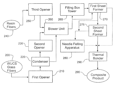
Turning now to FIG. 2, the opening of the wet reinforcement fibers and the
resin
fibers can best be seen. Although FIG. 2 depicts the opening of wet use
chopped strand
glass fibers (WUCS), a preferred wet reinforcement fiber, any suitable wet
reinforcement
fiber identified by one of skill in the art could be utilized in the
illustrated process. To
open the wet use chopped strand glass fibers, the WUCS glass fibers 200,
typically in the
form of a bale, package, or bundle of individual glass fibers, are fed into a
first opener 210,
which at least partially opens and filimentizes (for example, individualizes)
the WUCS
glass fibers 200. The first opener 210 may then dose or feed the WUCS glass
fibers 200 to
a condenser 220, where water is removed from the WUCS glass fibers 200. In
exemplary
embodiments, greater than 70% of the free water, for example, water that is
external to the
glass fibers is removed. Preferably, however, substantially all of the water
is removed by
the condenser 220. It should be noted that the phrase "substantially all of
the water" as it
is used herein is meant to denote that all or nearly all of the free water is
removed.
Once the WUCS glass fibers 200 have passed through the condenser 220, the
WUCS glass fibers 200 may then be passed through a second opener 230. The
second
opener 230 further filimentizes and separates the WUCS glass fibers 200.
To open the resin fibers 240, the resin fibers 240 are passed through a third
opener
250, where the resin fibers 240 are opened and filamentized. In alternate
embodiments
where the resin is in the form of a flake, granule, or powder, the third
opener 250 may be
replaced with an apparatus suitable for distributing the resin to the blower
unit 260 for
mixing with the WUCS glass fibers 200. A suitable apparatus would be easily
identified
by those of skill in the art. In embodiments where a resin in the form of a
flake, granule,
or powder is used in addition to the resin fibers 240, the apparatus
distributing the flakes,
granules, or powder does not replace the third bale opener 250. Alternatively,
a resin
7
CA 02540304 2006-03-27
WO 2005/037897 PCT/US2004/033839
powder, flake or granule may be added prior to thermal bonding in the thermal
bonder 290
in addition to or in place of the resin fibers 240.
Other types of fibers such as chopped roving, dry use chopped strand glass, A-
, C-
E- or S-type glass fibers, natural fibers (for example, jute, hemp, and
kenaf), aramid fibers,
metal fibers, ceramic fibers, mineral fibers, carbon fibers, graphite fibers,
polymer fibers,
or combinations thereof can be opened and filamentized by additional openers
(not shown)
depending on the desired composition of the final composite. These fibers can
be added to
the air stream in the blower unit 260 and mixed with the WUCS glass fibers 200
as
described below with respect .to the resin fibers 240. When such fibers are
added,
preferably from 10 - 30% of the fibers in the air stream consist of these
additional fibers.
The first, second, and third openers (210, 230, 250) are preferably bale
openers, but
may be any type of opener suitable for opening the bundle of wet reinforcement
fibers.
The design of the openers depends on the type and physical characteristics of
the fiber
being opened. Suitable openers for use in the present invention include any
conventional
standard type bale openers with or without a weighing device. The bale openers
may be
equipped with various fine openers and may optionally contain one or more
Ticker-in
drums or saw-tooth drums. The bale openers may be equipped with feeding
rollers or a
combination of a feeding roller and a nose bar. The condenser 220 may be any
known
drying or water removal device known in the art, such as, but not limited to,
an air dryer,
an oven, rollers, a suction pump, a heated drum dryer, an infrared heating
source, a hot air
blower, and a microwave emitting source.
After the WUCS glass fibers 200 and the resin fibers 240 have been opened and
filamentized, they are transferred to a blower unit 260 where the WUCS glass
fibers 200
and resin fibers 240 are blended together in an air stream (step 20 of FIG.
1). Preferably,
approximately 20 - 60% of the fibers in the air stream are reinforcement
fibers, for
example, WUCS glass fibers, and 40 - 80% of the fibers in the air stream are
resin fibers.
Preferably, the reinforcement fibers are present in the air stream in an
amount of from 40 -
60%.
The blended WUCS glass fibers 200 and resin fibers 240 are then transferred by
the air stream from the blower unit 260 to a first sheet former 270 where the
fibers are
formed into a sheet (step 30 of FIG. 1). In one exemplary embodiment of the
invention,
the opened WUCS glass fibers 200 and resin fibers 240 are transferred from the
blower
CA 02540304 2006-03-27
WO 2005/037897 PCT/US2004/033839
unit 260 to a filling box tower 265 to volumetrically feed the WUCS glass
fibers 200 and
resin fibers 240 into the first sheet former 265, such as by an electronic
weighing
apparatus. The filling box tower 265 may be located in the first sheet former
270 or may
be positioned external to the first sheet former 270. Additionally, the
filling box tower 265
may include baffles to further blend and mix the WUCS glass fibers 200 and
resin fibers
240 prior to entering the first sheet former 270.
In an alternative embodiment (not shown), the blended WUCS glass fibers 200
and
resin fibers 240 are blown onto a drum or series of drums covered with fine
wires or teeth
to comb the fibers into parallel arrays prior to entering the first sheet
former 270, as in a
carding process.
In a preferred embodiment, the sheet formed by the first sheet former 270 is
transferred to a second sheet former 275. The second sheet former 275 permits
the sheet
to have a substantially uniform distribution of the WUCS glass fibers 200 and
resin fibers
240. In addition, the second sheet former 275 permits the final composite
product 295 to
have high structural integrity. In particular, the composite product 295
formed may have a
weight distribution of from 100 - 3000 g/m2, with a preferred range of from
600 - 2000
g/m2.
The first and second sheet formers 270, 275 may include at least one licker-in
drum
having two to four sieve drums. Depending on the reinforcement fibers used,
the first and
second sheet formers 270, 275 may be equipped with one or more of the
following: a
condenser, a distribution conveyor, a powder strewer, and a chip strewer. A
sheet former
having a condenser and a distribution conveyor is typically used to achieve a
higher fiber
feed into the filling box tower and an increased volume of air through the
filling box
tower. In order to achieve an improved cross-distribution of the opened
fibers, the
distributor conveyor can run transversally to the direction of the sheet. As a
result, the
opened fibers are transferred from the condenser and into the filling box
tower with little
or no pressure.
The sheet exiting the first sheet former 270 and the second sheet former 275
has
little structural integrity. As a result, the sheet may optionally be
subjected to a needling
process in which needles are pushed through the fibers of the sheet to
entangle the WUCS
glass fibers 200 and resin fibers 240 (step 40 of FIG 1 ). The needling
process may occur
in a needle felting apparatus 280. The needle felting apparatus 280 may
include a web
9
CA 02540304 2006-03-27
WO 2005/037897 PCT/US2004/033839
feeding mechanism, a needle beam with a needleboard, barbed felting needles
ranging in
number from about S00 per meter to about 7,500 per meter of machine width, a
stripper
plate, a bed plate, and a take-up mechanism. Mechanical interlocking of the
WUCS glass
fibers 200 and resin fibers 240 is achieved by passing the barbed felting
needles repeatedly
S into and out of the sheet. An optimal needle selection for use with the
particular
reinforcement fiber and resin fiber chosen for use in the inventive process
would be easily
identified by one of skill in the art.
Either after the sheet forming step 30 or the optional needling step 40, the
sheet is
passed through a thermal bonder 290 to thermally bond the WUCS glass fibers
200 and
resin fibers 240. In thermal bonding, the thermoplastic properties of the
resin fibers are
used to form bonds with the reinforcement fiber (for example, WUCS glass
fibers 200)
upon heating. The thermal bonder 290 may include any known heating and bonding
method known in the art, such as oven bonding, oven bonding using forced air,
infrared
heating, hot calendaring, belt calendaring, ultrasonic bonding, microwave
heating, and
heated drums. Optionally, two or more of these bonding methods may be used in
combination to bond the WUCS glass fibers 200 and resin fibers 240 in the
sheet. The
temperature of the thermal bonder 290 may range from approximately
100°C to
approximately 250°C, depending on the melting point of the particular
resin fibers) used.
Although the thermoplastic properties of the resin fibers can be used to bond
reinforcement fibers (for example, WUCS glass fibers 200) and resin fibers
(for example,
resin fibers 240), single component binding fibers, bicomponent binding
fibers, and/or
powdered polymers may be added to the sheet to further bond the WUCS glass
fibers 200
and resin fibers 240. Typical examples of such fibers include polyester
fibers,
polyethylene fibers, and polypropylene-polyethylene fibers. Such bonding
agents) may be
added during the initial blending of the WUCS glass fibers 200 and the resin
fibers 240 in
the blower unit 260. If the bonding agent is in powdered or flaked form, it
can be added to
the sheet prior to the sheet entering the thermal bonder 290. Suitable methods
for adding
the bonding agent to the sheet include spraying the bonding agent onto the
sheet and
impregnating or coating the sheet with the bonding agent. When the sheet
containing the
bonding agents is passed through the thermal bonder 290, the bonding agent
further bonds
the WUCS glass fibers 200 and the resin fibers 240.
CA 02540304 2006-03-27
WO 2005/037897 PCT/US2004/033839
Another method that may be used to increase the strength of the sheet after it
exits
either the first sheet former 270 or the second sheet former 275 is chemical
bonding. In
chemical bonding, a bonding agent is applied to a sheet or web to bond the
reinforcement
fibers and resin fibers. Liquid based bonding agents, powdered adhesives,
foams, and, in
some instances, organic solvents can be used as the chemical bonding agent.
Suitable
examples of chemical bonding agents include, but are not limited to, acrylate
polymers and
copolymers, styrene-butadiene copolymers, vinyl acetate ethylene copolymers,
and
combinations thereof. For example, polyvinyl acetate (PVA), ethylene vinyl
acetate/vinyl
chloride (EVA/VC), lower alkyl acrylate polymer, styrene-butadiene rubber,
acrylonitrile
polymer, polyurethane, epoxy resins, polyvinyl chloride, polyvinylidene
chloride, and
copolymers of vinylidene chloride with other monomers, partially hydrolyzed
polyvinyl
acetate, polyvinyl alcohol, polyvinyl pyrrolidone, polyester resins, and
styrene acrylate
may be used as a bonding agent. The chemical bonding agent can be applied
uniformly by
impregnating, coating, or spraying the sheet. Although the temperature
requirements for
initiating chemical bonding is generally lower than the temperature
requirements for
thermally bonding the reinforcement fibers and the resin fibers, the chemical
bonding
process is not as desirable as thermal bonding because it requires the removal
of excess
bonding agents and further drying of the sheet.
The composite product 295, for example, a bonded mat, that exits the thermal
bonder 290 can be subsequently used as a reinforcement in a molding process to
produce
composite articles. For example, the composite product 295 can be used in
molding semi-
structural and acoustical parts for automobiles, in furniture industries such
as in making
seat backs, in making cubicle partitions, and can also be used in other
industrial
applications such as in parts for industrial and construction vehicles. The
composite
product 295 formed may expand (for example, loft) on reheating to provide
increased
stiffness and acoustic properties to the composite product 295. In addition,
the composite
product 295 can be further processed by conventional nip rolling (not shown)
or
laminating (not shown) to apply a scrim and a film. Subsequent shear slitting
(not shown)
provides a final product that can then be molded into a headliner or other
interior parts for
an automobile, such as trim panels, parcel shelves, sunshades, instrument
panel structures,
and door inners.
CA 02540304 2006-03-27
WO 2005/037897 PCT/US2004/033839
The process of manufacturing the composite product 295 that exits the thermal
bonder 290 may be conducted either in-line, that is, in a continuous manner,
or in
individual steps. Preferably, the process is conducted in-line. Moreover, any
additional
process steps such as adding specialty films, scrims, and/or fabrics are
considered within
the scope of the invention.
Turning now to FIG. 3, an alternate embodiment of the process of the present
invention can be seen. In this alternate embodiment, no resin fibers are
utilized. In
particular, wet reinforcement fibers 300, for example, wet use chopped strand
glass fibers,
are opened by passing the wet reinforcement fibers 300, typically in the form
of a bale,
package, or a bundle of individual glass fibers, consecutively through the
first opener 210,
the condenser 220, and optionally, the second opener (not shown in FIG. 3).
The wet
reinforcement fibers 300 are then conveyed by the blower unit 260 to the first
sheet former
270. Alternatively, the wet reinforcement fibers 300 may be conveyed to the
filling box
tower 265 prior to entering the first sheet former 270. The filling box tower
265
volumetrically feeds the reinforcement fibers 300 to the first sheet former
270. As in the
preferred embodiment described above, the sheet may optionally be conveyed to
the
second sheet former (not shown in FIG. 3) and/or the needle felting apparatus
280 for
mechanical strengthening. A binder resin 350 may be added prior to passing the
sheet
through the thermal bonder 290. The binder resin 350 may be added by any
suitable
manner, such as, for example, a flood and extract method or by spraying the
binder resin
350 on the sheet. Any binder resin capable of binding the wet reinforcement
fibers 300
can be used. Suitable examples include single and bicomponent fibers or
powders.
Further, the amount of binder can be varied depending of the type of mat
desired. The
sheet is then passed through the thermal bonder 290 to cure the binder resin
350 and
provide structural integrity to the reinforcement fibers 300. Alternatively, a
catalyst such
as ammonium chloride, p-toluene, sulfonic acid, aluminum sulfate, ammonium
phosphate,
or zinc nitrate may be used to improve the rate of curing and the quality of
the cured binder
resin. The resulting product 395, for example, a fibrous mat, may be used as
an insulation
product or in combination with other types of foam and polymeric substrates.
The process of the present invention provides many advantages over
conventional
dry-laid processes and wet-laid processes. In particular, the inventive
process provides a
substantially uniform distribution of reinforcement fibers and resin fibers in
both the mat
12
CA 02540304 2006-03-27
WO 2005/037897 PCT/US2004/033839
and composite product formed. The phrase "substantially uniform distribution
of
reinforcement fibers and resin fibers" is meant to indicate a uniform
distribution or a
nearly uniform distribution of the reinforcement fibers and the resin fibers.
In addition, the
use of wet use chopped strand glass fibers in the inventive process allows the
process to
have a lower cost, especially when compared to conventional dry-laid processes
that use
dry use chopped strand glass fibers. Additionally, the inventive method can be
tailored to
achieve numerous desired composite properties by adding additional types of
reinforcement fibers and/or resin fibers. Further, the sizing chemistry of the
reinforcement
fibers may be easily adapted to match the properties of individual types of
resin fibers. As
a result, a large variety of mats and composite products can be formed by the
process
according to the present invention.
In addition, the composite product formed may expand (for example, loft) on
reheating to provide increased stiffness and acoustic properties compared to
products
produced by conventional wet-laid processes. For example, an 800 GSM product
containing 55% WUCS glass formed by a conventional wet-laid process can loft
to
approximately 5 mm in height, whereas a composite containing 55% WUCS glass
formed
by the inventive process can loft to approximately 9 mm. This lofting enables
composites
formed using the inventive process to have greater sound absorption
capability.
Having generally described this invention, a further understanding can be
obtained
by reference to certain specific examples illustrated below which are provided
for purposes
of illustration only and are not intended to be all inclusive or limiting
unless otherwise
specified.
EXAMPLE
A composite product was produced according to an exemplary embodiment of the
present invention. In particular, wet use chopped strand glass fibers were
dried and
individualized by sequentially passing the WUCS fibers through a first bale
opener, a
condenser, and a second bale opener. Polypropylene fibers were opened by a
third bale
opener, and the opened polypropylene fibers were added to the WUCS glass
fibers and
transferred to a sheet former. Next, the sheet was passed through a thermal
bonding oven
which had a temperature of from 140°C to 200°C to form a
composite product. The
formed composite contained approximately SS% WUCS glass fibers and 45%
13
CA 02540304 2006-03-27
WO 2005/037897 PCT/US2004/033839
polypropylene fibers. In addition, a composite product was formed by a
conventional wet-
laid process using wet use chopped strand glass fibers and polypropylene
fibers. As in the
composite formed by the inventive process, the composite product formed by the
conventional method contained approximately 55% WUCS glass fibers and 45%
polypropylene fibers.
A comparison of the acoustical properties of the inventive composite product
and
the composite product formed by the convention wet-laid process were conducted
in
accordance to ASTM E1050. The results are shown in Table 1. A graphical
illustration of
Table 1 is shown in FIG. 4. As can be seen in FIG. 4, the composite product
produced by
the inventive process, which is depicted by the solid line, exhibited superior
sound
absorption compared to the composite product formed by the conventional wet-
laid
process, which is depicted by the dashed line.
Table 1
CONVENTIONAL
FREQUENCY INVENTIVE WET-LAID
Hz PROCESS PROCESS
250 0.02 0.02
500 0.06 0.04
1000 0.11 0.07
2000 0.28 0.18
2500 0.38 0.28
3150 0.52 0.43
4000 0.69 0.61
5000 0.85 0.70
6300 0.97 0.71
Table 2 shown below illustrates a comparison of various properties of a
composite
product formed by the inventive process, a composite formed by a conventional
wet-laid
1 S process, and a composite formed by a conventional dry-laid process.
Acoustical
measurements were made in accordance with ASTM E1050 and mechanical strength
measurements were made in accordance with SAE J949. As shown in Table 2, the
composite formed by the inventive process showed superior weight consistency,
14
CA 02540304 2006-03-27
WO 2005/037897 PCT/US2004/033839
reinforcement content consistency, and mechanical properties compared to the
composite
formed by the conventional dry-laid process. In addition, the composite formed
by the
inventive process demonstrated superior acoustical properties and thickness
after heating
(for example, lofting) compared to the composite formed by the conventional
wet-laid
S process. Further, it can be seen in Table 2 that the cost of forming the
composite using the
inventive process was lower than the cost of forming the composite using the
conventional
dry-laid process.
Table 2
CONVENTIONAL CONVENTIONAL
PROPERTIES INVENTIVE WET-LAID DRY-LAID
PROCESS PROCESS PROCESS
eight Consistency ~ 3 - 5% ~ 3 - 5% t 5 - 10%
einforcement Content
Consistency ~ 2% t 2% ~ 3 - 5%
echanical Properties100% 100% 80 - 90%
coustical Properties100% 70 - 90% 100%
hickness after 100% 50 - 60% 100%
Heating
Cost 100% 100% 110-120%
The invention of this application has been described above both generically
and
with regard to specific embodiments. Although the invention has been set forth
in what is
believed to be the preferred embodiments, a wide variety of alternatives known
to those of
skill in the art can be selected within the generic disclosure. The invention
is not
otherwise limited, except for the recitation of the claims set forth below.