Note: Descriptions are shown in the official language in which they were submitted.
CA 02540396 2006-03-27
WO 2005/004262 PCT/US2004/020597
FUEL CELLS COMPRISING LAMINAR FLOW INDUCED DYNAMIC
CONDUCTING INTERFACES, ELECTRONIC DEVICES COMPRISING
SUCH CELLS, AND METHODS EMPLOYING SAME
CROSS-REFERENCES TO RELATED APPLICATIONS
The present application is a continuation-in-part of application No.
10/053,187, filed on January 14, 2002, titled "Electrochemical cells
comprising
laminar flow induced dynamic conducting interfaces, electronic devices
comprising such cells, and methods employing same", inventors Larry J.
Markoski et al., hereby incorporated by reference in its entirety.
BACKGROUND
This invention relates to the field of induced dynamic conducting
interfaces. More particularly, this invention relates to laminar flow induced
dynamic conducting interfaces for use in micro-fluidic batteries, fuel cells,
and
photoelectric cells.
A key component in many electrochemical cells is a semi-permeable
membrane or salt bridge. One of the primary functions of these components
is to physically isolate solutions or solids having different chemical
potentials.
For example, fuel cells generally contain a semi-permeable membrane (e.g., a
polymer electrolyte membrane or PEM) that physically isolates the anode and
cathode regions while allowing ions (e.g., hydrogen ions) to pass through the
membrane. Unlike the ions, however, electrons generated at the anode
cannot pass through this membrane, but instead travel around it by means of
an external circuit. Typically, semi-permeable membranes are polymeric in
nature and have finite life cycles due to their inherent chemical and thermal
instabilities. Moreover, such membranes typically exhibit relatively poor
mechanical properties at high temperatures and pressures, which seriously
limits their range of use.
Fuel cell technology shows great promise as an alternative energy
source for numerous applications. Several types of fuel cells have been
constructed, including: polymer electrolyte membrane fuel cells, direct
CA 02540396 2006-03-27
WO 2005/004262 PCT/US2004/020597
2
methanol fuel cells, alkaline fuel cells, phosphoric acid fuel cells, molten
carbonate fuel cells, and solid oxide fuel cells. For a comparison of several
fuel cell technologies, see Los Alamos National Laboratory monograph LA-
UR-99-3231 entitled Fuel Cells: Green Power by Sharon Thomas and Marcia
Zalbowitz, the entire contents of which are incorporated herein by reference,
except that in the event of any inconsistent disclosure or definition from the
present application, the disclosure or definition herein shall be deemed to
prevail.
Although all fuel cells operate under similar principles, the physical
components, chemistries, and operating temperatures of the cells vary
greatly. For example, operating temperatures can vary from room
temperature to about 1000 °C. In mobile applications (for example,
vehicular
and/or portable microelectronic power sources), a fast-starting, low weight,
and low cost fuel cell capable of high power density is required. To date,
polymer electrolyte fuel cells (PEFCs) have been the system of choice for
such applications because of their low operating temperatures (e.g., 60-120
°C), and inherent ability for fast start-ups.
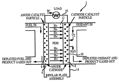
FIG. 1 shows a cross-sectional schematic illustration of a polymer
electrolyte fuel cell 2. PEFC 2 includes a high surface area anode 4 that acts
as a conductor, an anode catalyst 6 (typically platinum alloy), a high surface
area cathode 8 that acts as a conductor, a cathode catalyst 10 (typically
platinum), and a polymer electrolyte membrane (PEM) 12 that serves as a
solid electrolyte for the cell. The PEM 12 physically separates anode 4 and
cathode 8. Fuel in the gas and/or liquid phase (typically hydrogen or an
alcohol) is brought over the anode catalyst 6 where it is oxidized to produce
protons and electrons in the case of hydrogen fuel, and protons, electrons,
and carbon dioxide in the case of an alcohol fuel. The electrons flow through
an external circuit 16 to the cathode 8 where air, oxygen, or an aqueous
oxidant (e.g., peroxide) is being constantly fed. Protons produced at the
anode 4 selectively diffuse through PEM 12 to cathode 8, where oxygen is
reduced in the presence of protons and electrons at cathode catalyst 10 to
produce water.
CA 02540396 2006-03-27
WO 2005/004262 PCT/US2004/020597
3
The PEM used in conventional PEFCs is typically composed of a
perfluorinated polymer with sulphonic acid pendant groups, such as the
material sold under the tradename NAFION by DuPont (Fayetteville, NC)
(see: Fuel Cell Handbook, Fifth Edition by J. Hirschenhofer, D. Stauffer, R.
Engleman, and M. Klett, 2000, Department of Energy-FETL, Morgantown,
WV; and L. Carrette, K. A. Friedrich, and U. Stimming in Fuel Cells, 2001,
7(1 ), 5). The PEM serves as catalyst support material, proton conductive
layer, and physical barrier to limit mixing between the fuel and oxidant
streams. Mixing of the two feeds would result in direct electron transfer and
loss of efficiency since a mixed potential and/or thermal energy is generated
as opposed to the desired electrical energy.
Operating the cells at low temperature does not always prove
advantageous. For example, carbon monoxide (CO), which may be present
as an impurity in the fuel or as the incomplete oxidation product of an
alcohol,
binds strongly to and "poisons" the platinum catalyst at temperatures below
about 150 °C. Therefore, CO levels in the fuel stream must be kept low
or
removed, or the fuel must be completely oxidized to carbon dioxide at the
anode. Strategies have been employed either to remove the impurities (e.g.,
by an additional purification step) or to create CO-tolerant electrodes (e.g.,
platinum alloys). In view of the difficulties in safely storing and
transporting
hydrogen gas, the lower energy density per volume of hydrogen gas as
compared to liquid-phase fuels, and the technological advances that have
occurred in preparing CO-tolerant anodes, liquid fuels have become the
phase of choice for mobile power sources.
Numerous liquid fuels are available. Notwithstanding, methanol has
emerged as being of particular importance for use in fuel cell applications.
FIG. 2 shows a cross-sectional schematic illustration of a direct methanol
fuel
cell (DMFC) 18. The electrochemical half reactions for a DMFC are as follows
in acidic conditions:
CA 02540396 2006-03-27
WO 2005/004262 PCT/US2004/020597
4
Anode: CH30H + HBO ---~ C02 + 6 H+ + 6 a
Cathode: 3/2 02 + 6 H+ + 6 a --~ 3 H20
Cell Reaction: CH30H + 3/2 02 ---~ C02 + 2 H20
whereas in alkaline conditions the half reactions are:
Anode: CH30H + OH- ----~- 5 H20 + 6e + C02
Cathode: 3/2 O~ + 6 a + 3 H20 ~ 6 OH-
Cell Reaction: CH30H + 3/2 02 --~ C02 + 2 H20
As shown in FIG. 2, the cell utilizes methanol fuel directly, and does not
require a preliminary reformation step. DMFCs are of increasing interest for
producing electrical energy in mobile power (low energy) applications.
However, at present, several fundamental limitations have impeded the
development and commercialization of DMFCs.
One of the major problems associated with DMFCs is that the semi-
permeable membrane used to separate the fuel feed (i.e., methanol) from the
oxidant feed (i.e., oxygen) is typically a polymer electrolyte membrane (PEM)
of the type developed for use with gaseous hydrogen fuel feeds. These
PEMs, in general, are not fully impermeable to methanol. As a result, an
undesirable occurrence known as "methanol crossover" takes place, whereby
methanol travels from the anode to the cathode through the membrane. In
addition to being an inherent waste of fuel, methanol crossover also causes
depolarization losses (mixed potential) at the cathode and, in general, leads
to
decreased cell performance.
Therefore, in order to fully realize the promising potential of DMFCs as
commercially viable portable power sources, the problem of mefihanol
crossover must be addressed. Moreover, other improvements are also
needed including: increased cell efficiency, reduced manufacturing costs,
increased cell lifetime, and reduced cell size/weight. In spite of massive
CA 02540396 2006-03-27
WO 2005/004262 PCT/US2004/020597
research efforts, these problems persist and continue to inhibit the
commercialization and development of DMFC technology.
A considerable amount of research has already been directed at
solving the aforementioned problem of methanol crossover. Solutions have
5 typically centered on attempts to increase the rate of methanol consumption
at the anode, and attempts to decrease the rate of methanol diffusion to the
cathode (see: A. Heinzel, and V. M. Barragan in J. Power Sources, 1999, 84,
70, and references therein). Strategies for increasing the rate of methanol
consumption at the anode have included increasing catalyst loading (i.e.,
providing a larger surface area), increasing catalyst activity (i.e.,
increasing
efficiency), and raising operating pressure and/or temperature. Strategies for
decreasing the rate of methanol diffusion to the cathode have included
decreasing methanol concentrations, fabricating thicker NAFION membranes,
synthesizing new proton conducting materials having low permeability to
methanol, lowering cell operating temperature, and fabricating methanol
tolerant cathodes. However, to date, there remain pressing needs in DMFC
technology for significantly lowered fabrication costs, increased efficiency,
extended cell lifetimes, and appreciably reduced cell sizes/weights.
SUMMARY
The scope of the present invention is defined solely by the appended
claims, and is not affected to any degree by the statements within this
summary.
In a first aspect, the present invention provides a fuel cell that includes
(a) a first electrode; (b) a second electrode; and (c) a channel contiguous
with
at least a portion of the first and the second electrodes; such that when a
first
liquid is contacted with the first electrode, a second liquid is contacted
with the
second electrode, and the first and the second liquids flow through the
channel, a multistream laminar flow is established between the first and the
second liquids, and a current density of at least 0.7 mA/cm2 is produced.
In a second aspect, the present invention provides a device that
includes a fuel cell as described above.
CA 02540396 2006-03-27
WO 2005/004262 PCT/US2004/020597
6
In a third aspect, the present invention provides a portable electronic
device that includes a fuel cell as described above.
In a fourth aspect, the present invention provides a method of
generating an electric current that includes operating a fuel cell as
described
above.
In a fifth aspect, the present invention provides a method of generating
water that includes operating a fuel cell as described above.
In a sixth aspect, the present invention provides a method of
generating electricity that includes flowing a first liquid and a second
liquid
through a channel in multistream laminar flow, wherein the first liquid is in
contact with a first electrode and the second liquid is in contact with a
second
electrode, wherein complementary half cell reactions take place at the first
and the second electrodes, respectively, and wherein a current density of at
least 0.1 mA/cm2 is produced.
In a seventh aspect, the present invention provides a fuel cell that
includes a first electrode and a second electrode, wherein ions travel from
the
first electrode to the second electrode without traversing a membrane, and
wherein a current density of at least 0.1 mAlcm2 is produced.
In an eighth aspect, the present invention provides the improvement
comprising replacing the membrane separating a first and a second electrode
of a fuel cell with a multistream laminar flow of a first liquid containing a
fuel in
contact with the first electrode, and a second liquid containing an oxidant in
contact with the second electrode, and providing each of the first liquid and
the second liquid with a common electrolyte.
In a ninth aspect, the present invention provides a fuel cell that
includes (a) a support having a surface; (b) a first electrode connected to
the
surface of the support; (c) a second electrode connected to the surface of the
support and electrically coupled to the first electrode; (d) a spacer
connected
to the surface of the support, which spacer forms a partial enclosure around
at
least a portion of the first and the second electrodes; and (e) a microchannel
contiguous with at least a portion of the first and the second electrodes, the
microchannel being defined by the surface of the support and the spacer.
CA 02540396 2006-03-27
WO 2005/004262 PCT/US2004/020597
7
When a first liquid is contacted with the first electrode, and a second liquid
is
contacted with the second electrode, a multistream laminar flow is established
between the first and the second liquids, and a current density of at least
0.1
mA/cm2 is produced.
The presently preferred embodiments described herein may possess
one or more advantages relative to other devices and methods, which can
include but are but not limited to: reduced cost; increased cell lifetime;
reduced internal resistance of the cell; reduction or elimination of methanol
crossover or fouling of the cathode; ability to recycle left-over methanol
that
crosses over into the oxidant stream back into the fuel stream; ability to
increase reaction kinetics proportionally with temperature and/or pressure
without compromising the integrity of a membrane; and ability to fabricate a
highly efficient, inexpensive, and lightweight cell.
BRIEF DESCRIPTION OF THE DRAWINGS
FIG. 1 shows a cross-sectional schematic illustration of a polymer
electrolyte fuel cell.
FIG. 2 shows a cross-sectional schematic illustration of a direct
methanol fuel cell.
FIG. 3 shows a schematic illustration of modes of fluid flow.
FIG. 4 shows a schematic illustration of the relationship between input
stream geometry and mode of fluid flow.
FIG. 5 shows a schematic illustration of the relationship between
microfluidic flow channel geometry and mode of fluid flow.
F1G. 6 shows a schematic illustration of a diffusion-based micro-
extractor.
FIG. 7 shows a schematic illustration of a direct methanol fuel cell
containing a laminar flow induced dynamic interface.
FIG. 8A shows a schematic illustration of side-by-side microfluidic
channel configuration and 8B shows a face-to-face microfluidic channel
configuration.
CA 02540396 2006-03-27
WO 2005/004262 PCT/US2004/020597
8
FIG. 9 shows a perspective view of a laminar flow fuel cell in
accordance with the present invention.
FIG. 10 shows an exploded perspective view of the fuel cell shown in
FIG. 9.
FIG. 11 shows a plot of current vs. voltage for a copper-zinc laminar
flow fuel cell.
FIG. 12 shows a plot of current vs. voltage for a platinum-platinum
laminar flow fuel cell.
FIG. 13A shows the top view of a laminar flow cell with face-to-face
electrodes, and 13B its cross-section.
FIG. 14 shows a plot of potential vs. current density plot for a laminar
fuel cell with a ferrous sulfate and potassium permanganate fuel-oxidant
combination.
Fig. 15 shows a power density to potential plot for a laminar fuel cell
with a ferrous sulfate and potassium permanganate fuel-oxidant combination.
FIG. 16 shows a plot of potential vs. current density plot for a laminar
fuel cell with a formic acid and oxygen saturated aqueous sulfuric acid fuel-
oxidant combination.
Fig. 17 shows a power density to potential plot for a laminar fuel cell
with a formic acid and oxygen saturated aqueous sulfuric acid fuel-oxidant
combination.
FIG. 18 shows a plot of potential vs. current density plot for a laminar
fuel cell with a formic acid and potassium permanganate fuel-oxidant
combination.
Fig, 19 shows a power density to potential plot for a laminar fuel cell
with a formic acid and potassium permanganate fuel-oxidant combination.
FIG. 20 shows a plot of potential vs. current density plot for a laminar
fuel cell with a methanol and oxygen saturated aqueous sulfuric acid fuel-
oxidant combination.
Fig. 21 shows a power density to potential plot for a laminar fuel cell
with a methanol and oxygen saturated aqueous sulfuric acid fuel-oxidant
combination.
CA 02540396 2006-03-27
WO 2005/004262 PCT/US2004/020597
9
DETAILED DESCRIPTION
A revolutionary paradigm in cell design, which solves many of the
problems described above, has been discovered wherein the use of a PEM
has been eliminated entirely. An electrochemical cell in accordance with the
present invention does not require a membrane, and is therefore not
constrained by the limitations inherent in conventional membranes. Instead, a
mechanism has been developed by which ions can travel from one electrode
to another without traversing a membrane, and which allows proton
conduction while preventing mixing of the fuel and oxidant streams. This
mechanism, described more fully herein below, involves establishing laminar
flow induced dynamic conducting interfaces.
Throughout this description and in the appended claims, the phrase
"electrochemical cell" is to be understood in the very general sense of any
seat of electromotive force (as defined in Fundamentals of Physics, Extended
Third Edition by David Halliday and Robert Resnick, John Wiley & Sons, New
York, 1988, 662 ff.). The phrase "electrochemical cell" refers to both
galvanic
(i.e., voltaic) cells and electrolytic cells, and subsumes the definitions of
batteries, fuel cells, photocells (photovoltaic cells), thermopiles, electric
generators, electrostatic generators, solar cells, and the like. In addition,
throughout this description and in the appended claims, the phrase
"complementary half cell reactions" is to be understood in the very general
sense of oxidation and reduction reactions occurring in an electrochemical
cell.
Ideally, the structural componenfis of a DMFC will have the following
characteristics. Preferably, the membrane should (1 ) be resistant to harsh
oxidizing/reducing environments; (2) possess mechanical toughness; (3) be
resistant to high temperatures and pressures (e.g., 0-160 °C and 1-10
atm);
(4) be impermeable to methanol under all operating conditions; (5) conduct
protons with minimal ohmic resistance and mass transport losses; and (6) be
composed of lightweight and inexpensive materials. Both the anode and
cathode, preferably, should (1 ) exhibit high catalytic activity; (2) possess
a
large surface area; (3) require minimal amounts of precious metals; and (4) be
CA 02540396 2006-03-27
WO 2005/004262 PCT/US2004/020597
easily to fabricated. In addition, the anode should preferably show tolerance
to carbon monoxide, and the cathode should preferably show tolerance to
methanol if so needed. The integrated fuel cell assembly itself should
preferably (1 ) have few moving parts; (2) require no external cooling system;
5 (3) require no fuel reformer or purifier; (4) be composed of durable and
inexpensive components; (5) be easily fabricated; (6) be easily integrated
into
fuel cell stacks; and (7) provide highly efficient energy conversion (i.e., at
least
50%).
Heretofore, there has been no single fuel cell design that successfully
10 incorporates all of the aforementioned attributes. However, it has now been
discovered that by completely eliminating the PEM from the DMFC, and by
redesigning the system to function on the microfluidic scale, one or more of
these attributes can be achieved. In the absence of a PEM, a mechanism to
allow proton conduction while preventing mixing of the fuel and oxidant
streams is needed. Such a mechanism, described more fully herein below,
can be established in microfluidic flow channels through a phenomenon
known as "multistream laminar flow," whereby two liquid streams flow side-by-
side in physical contact (thereby enabling proton conduction), without mixing
and in the complete absence of a physical barrier or membrane. The two
liquids can be miscible or immiscible. Obviation of a physical membrane for
stream segregation and proton transport from a fuel cell significantly
decreases manufacturing costs and increases the efFiciency and versatility of
the cell.
As shown in FIG. 3, fluid flow can be categorized into two regimes:
laminar flow and turbulent flow. f n steady or laminar flow (FIG. 3), the
velocity
of the fluid at a given point does not change with time (i.e., there are well-
defined stream lines). In turbulent flow the velocity of the fluid at a given
point
does change with time. While both laminar and turbulent flow occur in natural
systems (e.g., in the circulatory system), turbulent flow generally
predominates on the macroscale. In contrast, laminar flow is generally the
norm on the microfluidic scale.
CA 02540396 2006-03-27
WO 2005/004262 PCT/US2004/020597
11
An indicator of the state of a flow stream for a filuid under flow can be
expressed as a dimensionless quantity known as the Reynolds number (Re).
The Reynolds number is defined as the ratio of inertial forces to viscous
forces, and can be expressed as:
Re = pvL/~,
where L is the characteristic length in meters, p is the density of the fluid
in
grams/cm3, v is the linear velocity in meters/sec , and ~ is the viscosity of
the
fluid in grams/(sec)(cm).
There is a transitional critical value of Re for any given geometry above
which flow is said to be turbulent and below which flow is said to be laminar.
For typical fluidic devices, the transition from laminar to turbulent flow has
been empirically determined to occur around Re = 2,300. Formulae to
calculate Re for specific geometries are well known (see: Micromachined
Transducers: Sourcebook by G. T. A. Kovacs, McGraw-Hill, Boston, 1998). In
some microchannel geometries, flow is strictly laminar, reducing the mixing of
two miscible streams to the low levels due to the interdiffusion of both
liquids
into each other. However, as shown in FIG. 4, the geometry of the input
streams can greatly affect turbulence and mixing. A T junction brings two
miscible streams together in a laminar flow, which is maintained without
turbulent mixing. In contrast, introducing the two streams in an arrow-type
junction would produce turbulent flow and subsequent mixing.
Geometry is not the only variable that affects the degree of mixing.
The residence time, or flow rates of solutions can have an impact as well.
The average time for a particle to diffuse a given distance depends on the
square of that distance. A diffusion time scale (Ta) can be expressed as
Ta=L2/D
where L is the relevant mixing length in micrometers and D is the diffusion
coefficient. The rate of diffusion for a given molecule is typically
determined
by its sire. A table of diffusion coefficients for some common molecules is
shown below in Table 1 (see: J. P. Brody, and P. Yager, "Diffusion-Based
Extraction in a Microfabricated Device," Sensors and Actuators, Jan., 199?,
CA 02540396 2006-03-27
WO 2005/004262 PCT/US2004/020597
12
A58, no. 1, pp. 13-18). As may be seen from this Table, the proton (H*) has
the highest diffusion coefficient in water at room temperature.
Table 1
Molecular Wei ht Diffusion Coefficient
Water Soluble Molecule(AMU) g In Water at Room
Temp
m /sec
H+ 1 9,000
Na* 23 2,000
O~ 32 1,000
Glycine ~ 75 1,000
Hemoglobin 6x10" 70
Myosin 4x10 10
Tobacco Mosaic Virus4x10' S
When two fluids with differing concentrations or compositions of
molecules are forced to flow parallel to one another in a single channel,
extraction of molecules can be accomplished on the basis of diffusion
coefficient differences. For example, as shown in FIG. 6, Na* can be
extracted from blood plasma by controlling channel dimension, flow rate, and
the dwell time the two streams are in contact, thus producing a continuous
micro-extractor (see: Brody reference, vide supra).
It has been discovered that multistream laminar flow between two
miscible streams of liquid induces an ultra-thin dynamic conducting ("semi-
permeable") interface (hereinafter "induced dynamic conducting interface" or
"IDCI"), which wholly replaces the PEMs or salt bridges of conventional
devices. The iDCI can maintain concentration gradients over considerable
flow distances and residence times depending on the dissolved species and
the dimensions of the flow channel.
An electrochemical cell embodying features of the present invention
includes (a) a first electrode; (b) a second electrode; and (c) a channel
contiguous with at Least a portion of the first and the second electrodes.
When a first liquid is contacted with the first electrode, a second liquid is
contacted with the second electrode, and the first and the second liquids flow
CA 02540396 2006-03-27
WO 2005/004262 PCT/US2004/020597
13
through the channel, a multistream laminar flow is established between the
first and the second liquids, and a current density of at least 0.1 mA/cm2 is
produced.
Flow cell designs embodying features of the present invention
introduce a new paradigm for electrochemical cells. A fuel cell 20 embodying
features of the present invention that does not require a PEM nor is subject
to
several of the limitations imposed by conventional PEMs is shown in FIG. 7.
In this design, both the fuel input 22 (e.g. an aqueous solution containing
MeOH and a proton source) and the oxidant input 24 (e.g., a solution
containing dissolved oxygen or hydrogen peroxide and a proton source) are in
liquid form. By pumping the two solutions into the microchannel 26,
multistream laminar flow induces a dynamic proton-conducting interface 28
that is maintained during fluid flow. If the flow rates of the two fluids are
kept
constant and the electrodes are properly deposited on the bottom and/or top
surfaces of the channel, the IDCI is established between anode 30 and
cathode 32.
A proton gradient is created between the two streams and rapid proton
diffusion completes the circuit of the cell as protons are produced at anode
30
and consumed at cathode 32. In this case, the IDCI prevents the two
solutions from mixing and allows rapid proton conduction by diffusion to
complete the circuit.
Preferably, the liquid containing the fuel and the liquid containing the
oxidant each contains a common electrolyte, which is preferably a source of
protons (e.g., a Bronsted acid). A portion of these externally provided
protons
may be consumed in the half cell reaction occurring at the cathode. Thus, a
reliance on pure diffusion for conveying protons from the fuel stream to the
oxidant stream can be avoided and current densities of at least 0.1 mAlcm2
can be achieved.
Preferably, an electrochemical cell embodying features of the present
invention produces current densities of at least 0.1 mA/cmz, more preferably
of at least 1 mA/cm2, still more preferably of at~ least 2 mA/em2. A current
density of 27 mA/cm2 has been produced in accordance with presently
CA 02540396 2006-03-27
WO 2005/004262 PCT/US2004/020597
14
preferred embodiments. Although there is presently no preferred limit to the
amount of current density produced by an electrochemical cell embodying
features of the present invention, it is preferred that the current density
produced by a cell be substantially matched to the requirements for a
particular application. For example, if an electrochemical cell embodying
features of the present invention is to be utilized in a cellular phone
requiring a
current density of about 10 mA/cm2, it is preferred that the electrochemical
cell
produce a current density that is at least sufficient to match this demand.
Advantages of the design shown in FIG. 7 include but are not limited to
the following: reduced cost due to the elimination of a PEM; increased cell
lifetime due to the continual regeneration of the IDCI, which neither wears
out
nor fails under flow; reduced internal resistance of the cell due to the
infinite
thinness of the IDCI; reduction or elimination of methanol crossover or
fouling
of the cathode since, with proper design, diffusion occurs only downstream of
the cathode; ability to recycle back into the fuel stream left-over methanol
that
crosses over into the oxidant stream; ability to increase reaction kinetics
proportionally with temperature and/or pressure without compromising the
integrity of the IDCI; ability to fabricate a highly efficient, inexpensive,
and
lightweight cell through optimization of cell dimensions, flow rate, fuel
(concentration and composition), oxidant (concentration and composition) and
electrodes (surface area, activity, and chemical composition).
In an optimized cell design, the methanol is completely consumed
before it diffuses into the oxidant stream. This is feasible if the
concentration
of methanol is controlled by a methanol sensor coupled to a fuel injector or
to
a flow rate monitor. Alternatively, a water immiscible oxidant fluid stream
having a very low affinity for methanol and a high affinity for oxygen and
carbon dioxide can be used in conjunction with the laminar flow-type cell
shown in FIG. 7. At least one such family of fluids (viz., perfluorinated
fluids
such as perfluorodecalin available from F2 Chemicals Ltd., Preston, UK) has
been successfully used in respiration-type fluids for medicinal applications.
These fluids exhibit an extremely high affinity for oxygen and extremely low
affinities for methanol and water. They are chemically inert and thermally
CA 02540396 2006-03-27
WO 2005/004262 PCT/US2004/020597
stable. When these fluids are doped with NAF10N or an alternative proton
source, they become proton conducting. Thus, inasmuch as methanol is
soluble in the aqueous fuel stream only, the unwanted problem of methanol
crossover into the water immiscible oxidant fluid stream is reduced or
5 eliminated. Moreover, since both liquids are excellent heat exchangers, an
external cooling system is not required.
Cell and electrode dimensions and electrode placement affect cell
efficiency. FIG.8 shows two alternative cell designs. In FIG. 8A, the anode
and cathode are positioned side-by-side, analogous to the placement shown
10 in FIG. 7. In FIG. 8B, the anode and cathode are positioned face-to-face.
The optimization of cell dimensions can be achieved via computer modeling
(e.g., using fluid flow modeling programs, Microsoft EXCEL software, etc.) to
correlate optimum laminar flow conditions (i.e., minimum mixing) with easily
fabricated channel dimensions and geometries. Critical values for the
15 Reynolds number can be calculated for an array of cell designs with respect
to channel width, depth, length, flow rate, and interfacial surface area. In
this
manner, a channel design that provides the greatest power output and highest
fuel conversion can be determined.
When appropriate electrode dimensions and placement of electrodes
have been determined as set forth above, the electrodes are then patterned
onto a support (e.g., a soda lime or Pyrex glass slide). The electrodes may
be sacrificial electrodes (i.e., consumed during the operation of the
electrochemical cell) or non-sacrificial electrodes (i.e., not consumed by the
operation of the electrochemical cell). In preferred embodiments, the
electrodes are non-sacrificial. In any event, the type of electrode used in
accordance with the present invention is not limited. Any conductor with
bound catalysts that either oxidize or reduce methanol or oxygen is preferred.
Suitable electrodes include but are not limited to carbon electrodes, platinum
electrodes, palladium electrodes, gold electrodes, conducting polymers,
metals, ceramics, and the like,
The electrode patterns can be produced by spray coating a glass slide
and mask combination with dispersions of metallic (preferably platinum)
CA 02540396 2006-03-27
WO 2005/004262 PCT/US2004/020597
16
particles in an organic or aqueous carrier. A preferred dispersion of platinum
particles in an organic carrier is the inexpensive paint product sold under
the
trade name LIQUID BRIGHT PLATINUM by Wale Apparatus (Hellertown,
PA). The patterned slide is then baked in a high temperature oven in the
presence of oxygen or air to produce a thin conductive layer of pure platinum.
This technique enables production of thin, high surface area, mechanically
robust, low resistance platinum electrodes on glass slides. To increase the
carbon monoxide tolerance of these electrodes, they can be decorated with
ruthenium using chemical vapor deposition, sputtering, or a technique known
as spontaneous electroless deposition (see: A. Wieckowski et al. J. Catalysis,
2001, in press).
Once the electrodes have been patterned on a support, the
microchannel can be constructed readily from flat, inexpensive, precision
starting materials as shown in FIGS. 9-10 using techniques such as those
described by B. Zhao, J. S. Moore, and D. J. Beebe in Science, 2001, 297,
1023-1026. Microchannel 34 can be constructed from commercially available
glass slides 36 and cover slips 38. The microchannel 34 can be sealed with
an ultraviolet-based chemically resistant adhesive. A preferred ultraviolet-
based chemically resistant adhesive is that sold by Norland Products, Inc.
(Cranberry, NJ), which is chemically resistant to most water miscible
solvents.
The cell thus produced will have chemical resistance and can be employed as
a single channel laminar flow DMFC.
Once a single channel laminar flow DMFC has been assembled,
optimization experiments can be performed in which the efficiency of the cell
is evaluated with respect to concentration of methanol, concentration of
proton, oxidant composition, flow rate, and temperature. Evaluation of cell
performance is determined based on cell potential, current density, peak
power, and power output. The single channel laminar flow DMFC is reusable,
and multiple experiments can be performed with the same cell.
The fuel and oxidant are introduced into the flow channel with the aid of
one or more pumps, preferably with the aid of one or more high-pressure
liquid chromatography (HPLC) fluid pumps. For example, the flow rate of the
CA 02540396 2006-03-27
WO 2005/004262 PCT/US2004/020597
17
fuel and oxidant streams can be controlled with two HPLC pumps to enable
precise variation of the flow rate from 0.01 to 10 mL/min. This approach
allows for the use of large reservoirs of fuel and oxidant that can be heated
to
constant temperatures and maintained under inert atmosphere, air, or oxygen,
as needed. The effluent streams can be monitored for the presence of
methanol to quantify chemical conversion, cell efficiency, and methanol
crossover, by sampling the effluent stream and subjecting it to gas
chromatographic analysis. In this manner, the optimized operating conditions
for a single channel laminar flow DMFC can be determined.
It is noted that the fabrication technique described above can be readily
extended to the construction of multi-channel laminar flow DMFC stacks for
use in devices having increased power requirements. Likewise, the methods
described above for optimizing and quantifying the efficiency of single
channel
laminar flow DMFCs can be used to optimize and quantify the efficiency of
arrayed multi-channel cell designs. The electrodes in such multi-channel cell
designs can be connected in both series and parallel configurations to
investigate the parameters of maximum cell voltage and current.
A single channel laminar flaw DMFC can be constructed using
materials with sufficient structural integrity to withstand high temperatures
and/or pressures. Graphite composite materials (similar to those used in
DMFGs from Manhattan Scientific) or ceramic materials (similar to those used
in DMFCs from Los Alamos National Laboratory) can be used in view of their
light weight, mechanical integrity, high temperature stability, corrosion
resistance, and low cost. In addition, a variety of fabrication techniques can
be used to produce the microchannel including micro-milling, micro-molding,
and utilizing an Electric Discharge Machine (EDM) such as is used in the
fabrication of injection molds. The electrodes can be deposited as described
above, and a chemically inert gasket used to seal the cell. The gasket can be
made, for example, from a fluoropolymer such as polytetrafluoroethylene sold
under the trade name TEFLON by DuPont (Wilmington, DE). Alternative
sealing techniques such as those utilized by Manhattan Scientifics can also
be employed. Optimization and quantification of the efficiency of these single
CA 02540396 2006-03-27
WO 2005/004262 PCT/US2004/020597
18
channel laminar flow DMFCs can be achieved using the techniques described
above.
Although the manner of establishing and utilizing an induced dynamic
conducting interface in accordance with the present invention has been
described primarily in reference to a DMFC, it is emphatically noted that the
concepts and principles described herein are general to all manner of
electrochemical cells, including but not limited to other types of fuel cells
and
to batteries, photocells, and the like.
The manner in which a device embodying features of the present
invention is made, and the process by which such a device is used, will be
abundantly clear to one of ordinary skill in the art based upon joint
consideration of both the preceding description, and the following
representative procedures. It is to be understood that many variations in the
presently preferred embodiments illustrated herein will be obvious to one of
ordinary skit! in the art, and remain within the scope of the appended claims
and their equivalents.
EXAMPLES
A Laminar Flow Cell Usina Sacrificial Electrodes
Flat copper and zinc electrodes (ca. 0.125 x 20 x 3 mm) were
imbedded into a block of polycarbonate by micro-machining channels and
adhering the electrodes into these channels to create a flat surface. The
electrodes were both of equivalent size and ran parallel to each other with a
gap of approximately 5 mm there between. On top of this electrode assembly
was assembled a flow channel composed of microscope coverglass as shown
in Figure 11. The cell was sealed with UV glue (Norland Products Inc.,
Cranberry, NJ) and the input adapters were secured with commercially
available epoxy (Loctite Quick Set Epoxy, Rocky Hill, CT). Once the cell was
assembled, aqueous solutions of 2M copper sulphate and zinc sulphate were
prepared. The zinc sulphate solution was brought into the channel first over
the zinc electrode with the aid of a syringe pump (this filled the entire
channel
with liquid and care was take to remove all air bubbles). The copper sulphate
CA 02540396 2006-03-27
WO 2005/004262 PCT/US2004/020597
19
solution was then introduced over the copper electrode. Laminar flow was
established between the electrodes and a current to voltage plot was
developed as shown in FIG. 11. The flow rates of the two solutions were held
constant and equal to each other (e.g., at 0.1 mL/min) in order for the
induced
dynamic conducting interface to exist between the two electrodes. If the flow
rates were different and the opposing stream touched the opposite electrode,
the cell would short and produce no current. Thus, in accordance with the
present electrode configurationit is preferred that the flow rates of the two
solutions be similar (i.e., differ by less than about 15 percent, more
preferably
by less than about 10 percent, and still more preferably by less than about 5
percent).
A Laminar Flow Cell Usina Non-Sacrificial Electrodes
Two flat platinum electrodes (ca. 0.125 x 20 x 3 mm) were imbedded
into a block of polycarbonate by micro-machining channels and adhering the
electrodes into these channels, creating a flat substrate with exposed
electrode surfaces. The electrodes were both of equivalent size and ran
parallel to each other with a gap of approximately 5 mm. On top of this
electrode assembly was assembled a flow channel composed of double stick
tape and a microscope coverglass as shown in Figure 11. The cell was
sealed and the input adapters were secured with commercially available
epoxy (Loctite Quick Set Epoxy, Rocky Hill, CT). Next, solutions of iron (II)
chloride in 10% HZSOa (0.6M) and potassium permanganate in 10% HZS04
(0.076M) were prepared. The iron solution was brought into the channel first
over the platinum electrodes with the aid of a syringe pump (this filled the
entire channel with liquid and care was take to remove all air bubbles). The
permanganate solution was then introduced and laminar flow was visibly
established between the electrodes. The flow rates of the two solutions were
held constant and equal to each other in order for the induced dynamic
conducting interface to exist between the two electrodes. Current flow (i) and
cell potential (V) were measured with the aid of a variable resistor and
potentiometer. A current to voltage plot was then developed as shown in
CA 02540396 2006-03-27
WO 2005/004262 PCT/US2004/020597
Figure 12, thus confirming the functioning of the device as an electrochemical
cell. The flow rate was held at 0.05 mL/min and the reproducibility was good.
The power plot for this data can also be seen in Figure 12. The
electrochemical half reactions for the cell are as follows:
5
Mn04 (aq) + 8 H* (aq) + 5 e --~. Mn2* (aq) + 4 H20 E° =1.507 V
5 Fe2+ (aq) --~ 5 Fe3* (aq) + 5 a E° = -0.75 V
E°cen = 0.75 V
This particular chemistry was chosen to demonstrate the feasibility of a
10 reaction in which all products and reactants remained in solution and
utilized a
common electrolyte. Since the electrodes are not involved in the reaction,
their lifetimes are very long and the cell will continue to operate as long as
oxidant and reductant are provided. The IDCI has an infinite lifetime because
it is constantly being regenerated under flow. With this particular reaction,
the
15 dark purple permanganate solution becomes colorless at the cathode under
high current conditions providing a visible means of measuring current flow.
Should the effluent stream be purple, it indicates that oxidant has not been
completely consumed. The color change occurs only at the cathode surface
(not at the intertace), further indicating true laminar flow with ion
conductivity.
20 This technology can be transferred directly to applications involving
DMFCs.
A Laminar Flow Fuel Cell with Face-to-Face Electrodes
As seen in Figures 13 A and 13 B, the fuel cell system 1301 has the
anode and cathode electrodes in a face-to-face orientation similar to Figure
8B. Using a very similar fabrication scheme as described below, the side-by-
side orientation of the cathode and anode electrodes as shown in Figure 8A
may also be obtained.
The fiuel cell system 1301 includes multiple parts that are stacked in
layers. In Figure 13 a schematic top view and a cross sectional view is given
CA 02540396 2006-03-27
WO 2005/004262 PCT/US2004/020597
21
of such a stacked layer assembly, wherein the fuel stream 1302 and oxidant
stream 1304 will convene at a Y-shaped junction and continue to flow
laminarly in parallel in the common fluidic channel 1306 in which the catalyst
covered electrodes 1308 cover part of the walls.
The centre! support layer 1300 that carries the outline of the fluidic
channel 1306 and supports the catalyst covered anode and cathode
electrodes 1308 with their leads 1310 may be fabricated according to the
following procedure. First, a negative of the channel shape, a master, is
obtained in thick photoresist (SU-8 series, Microchem, Newton, MA) via
standard photolithographic techniques using transparency films as the mask.
This master is replicated into an elastomeric mold, typically a silicone
rubber
(poly(dimethylsiloxane) (PDMS) or SILGARDT"" 184, Dow Corning, Midland,
MI), to obtain a positive relief structure of the fluidic channel 1306 (for a
detailed description of this type of procedure see Duffy et al., Anal. Chem.
(1998) 70, pp. 4974-4984).
The mold is replicated to obtain the desired central support layer. For
example, a liquid UV-curable polyurethane adhesive (Norland Optical
Adhesive no. 81, Norland Products, Cranbury, NJ) is applied and spread
evenly over the elastomeric mold, then a flat layer of the elastomeric
material
is applied and clamped on top (i) to level the liquid adhesive, and (ii) to
ensure
that the top layer touches the top of the positive relief ffuidic channel
1306.
This clamped assembly is then treated with UV light according to the
manufacturer's instructions. Finally, the elastomeric top layer and the
positive-
relief elastomeric mold are peeled away to yield a freestanding central
support
structure (0.5-3 mm in thickness) carrying the outlines (sidewalls) of the Y-
shaped fluidic channel 1306 system.
Shadow evaporation of metals (for example, via an ATC 2000
sputtering system, AJA International Inc, North Scituate, MA) is used to apply
the anode and cathode electrodes 1308 in the appropriate shapes to fihe
central support layer. Typically, chromium (usually 2-50 nm) is applied as an
adhesion layer, followed by gold (usually 50-1500 nm) as the seed layer for
consecutive electrodeposition of the catalyst, for example Platinum Black
CA 02540396 2006-03-27
WO 2005/004262 PCT/US2004/020597
22
plated on gold on each electrode separately at 2.6 V with a current density of
about 10 mA/cm2 for 3 minutes.
In the fuel cell system described herein both the anode and cathode
consist of electrodeposited Platinum Black. Similar procedures may be used ,
to apply other metals or combinations thereof.
The central support layer 1300 carrying the electrodes 1308 is clamped
between two gasket layers 1314 (typically 1-10 mm in thickness) that form the
fop and the bottom wall of the fluidic channel 1306 embedded in the central
support structure 1300. These two gasket layers 1314 are shaped for easy
access to the leads 1310 that are connected to the electrodes 1308. Typically,
slabs of a silicone elastomer (for example PDMS) are used as gaskets. Other
materials including glass, PLEXIGLASTM, other gasket materials (for example,
rubber) or a combination of any of such materials could be used as well.
To guide the fuel and oxidant into the Y-shaped channel system and to
guide the waste stream out of the channel, fluidic tubing is placed in the
gaskets. Typically, holes are punched exactly at the three ends 1320 of the Y-
shaped channel design. If the gasket material is elastomeric (for example,
PDMS) the tubes may be kept in place by a pressure-fit mechanism.
To provide rigidity and robustness to the layered system, more rigid top
and bottom capping layers 1322 may be applied, such as 2 mm-thick
PLEXIGLAS"". The now five layer assembly is kept together using clamps
such as standard paper binding clips.
The procedure described above was used to manufacture a laminar
flow cell with a channel 3.0 cm long, 1.0 mm high, and 1.0 mm electrode-to-
electrode distance. This cell was used for experimenting with the fuel-oxidant
combinations reported in Table 2. All experiments were run at room
temperature at a 0.5 mllmin cell flow rate. Thus, in accordance with the
present electrode configuration (face to face), the flow rates of the fuel and
oxidant need not be equal, as even at flow rates differing by 90% the streams
cannot cross over.
CA 02540396 2006-03-27
WO 2005/004262 PCT/US2004/020597
23
Table 2
Exp. Fuel Oxidant Results
A FeS04 0.72 M in KMn04 0.144 M in Fig, 14. Load Curve
10% aqueous H2S04 10% aqueous H2S04 Fig. 15. Power Density
Curve
B 10% aqueous 1 N aqueous H2S04 Fig. 16. Load Curve
HCOOH saturated with Fi . 17. Power Densit
02
C 10% aqueous KMn04 0.144 M in FIG. 18. Load Curve
HCOOH 10% aqueous H2S04 Fig. 19. Power Density
Curve
D MeOH 1 M in water 1 N aqueous H2S04 FIG. 20. Load Curve
saturated with Fig. 21. Power Density
02
Curve
Saturated oxygen solutions were obtained by bubbling oxygen gas
(99.99%, S.J. Smith Welding Supply) through an aqueous solution of 1-50%
H2S04 at 298 K for at least 15 minutes. Oxygen solutions may also be
prepared by bubbling oxygen or air in aqueous emulsions of fluorinated
solvents as described in "Emulsions for Fuel Cells", filed June 27, 2003,
inventors Larry J. Markoski et al., U.S. Patent Application Serial No. ,
Attorney Docket No. 09800240-0048, hereby incorporated by reference in its
entirety. For example, an oxygen solution may be obtained by bubbling
oxygen gas or air in an emulsion made by emulsifying 10 mL of
perfluorodecaline (PFD) in 20 mL of 0.5 M sulfuric acid with an amount of
ZONYL~ FS-62 equivalent to 1 % of the total weight of the emulsion.
Other examples of oxidants are solutions of ozone, hydrogen peroxide,
permanganate salts, manganese oxide, fluorine, chlorine, bromine, and
iodine. Other examples of fuels are solutions of ethanol, propanol,
formaldehyde, ferrous chloride, and sulfur.
Current flows (I) and cell potentials (V) were measured with the aid of
either a variable resistor, a potentiostat or a multimeter. The Load Curves
and Power Density plots were then developed as shown in Figures 14, 95, 16,
and 17, thus confirming the functioning of the device as an electrochemical
cell.
CA 02540396 2006-03-27
WO 2005/004262 PCT/US2004/020597
24
The laminar flow induced interface technology described herein is
applicable to numerous cells systems including but not limited to batteries,
fuel cells, and photoelectric cells. It is contemplated that this technology
will
be especially useful in portable and mobile fuel cell systems, such as in
cellular phones, laptop computers, DVD players, televisions, palm pilots,
calculators, pagers, hand-held video games, remote controls, tape cassettes,
CD players, AM and FM radios, audio recorders, video recorders, cameras,
digital cameras, navigation systems, wristwatches, and the like. It is also
contemplated that this technology will also be useful in automotive and
aviation systems, including systems used in aerospace vehicles and the like.
Throughout this description and in the appended claims, it is to be
understood that elements referred to in the singular (e.g., a microchannel, a
fuel cell, a spacer, a fuel input, an oxidant input, and the like), refer to
one or a
plurality of such elements, regardless of the tense employed.
Obviously, numerous modifications and variations of the present
invention are possible in light of the above teachings. It is therefore to be
understood that within the scope of the appended claims, the invention may
be practiced otherwise than as specifically described herein.