Note: Descriptions are shown in the official language in which they were submitted.
CA 02540511 2006-03-28
WO 2005/033442 PCT/US2004/032439
System for Vertically Forming Concrete Panels
BACKGROUND OF THE INVENTION
Field of the Invention
The present invention relates generally to a system for vertically forming
concrete
panels for use in erecting concrete fences, walls and related structure.
Related Art
Vertically oriented concrete panels have been used for a number of years in
applications including concrete fences, sound walls, partitions, etc. Concrete
panels are
often poured and cured in a central manufacturing area and shipped as cured
panels to job
sites, where the panels can be assembled into a fence or similar, structure.
It is often
desirable to apply a textured, decorative finish to such concrete panels to
enhance the
appearance of the panels. Decorative finishes such as pseudo-brick finishes,
pseudo-rock
wall finishes, etc., give the concrete panels a more aesthetically pleasing
appearance, and
in some cases, such as in sound wall applications, can increase the
effectiveness of the
concrete panels.
Due to the difficulties inherent in vertically forming panels from uncured
concrete, conventional processes often utilize a horizontal mold system to
form panels
which will be used in a vertical orientation. In one such method, a horizontal
mold is
formed that is relatively long and wide in relation to its vertical thickness;
for instance 12
feet in length by 6 feet in width by 4 inches in vertical thickness. Such a
horizontal mold
would produce a vertical panel approximately 12 feet in length, 6 feet in
height and 4
inches in horizontal thickness. While this process can provide a vertical
panel having the
desired vertical dimensions, it generally consumes a considerable amount of
human labor
and space. For instance, simultaneously pouring a sufficient number of
concrete panels to
erect 120 linear feet of fence would require at least 720 square feet of floor
space to erect
the molds, and additional floor space for movement of workers; equipment, etc.
In addition to the excessive labor hours and space such a process requires,
applying a decorative finish on both sides of the horizontally-poured panel
has proved
difficult. For example, it is relatively easy to apply a decorative imprint on
a bottom
surface of a horizontal mold by placing an inverted, patterned mold form on
the bottom of
the mold which then forms the decorative imprint on lower side of the concrete
panel. As
CA 02540511 2006-03-28
WO 2005/033442 PCT/US2004/032439
2
the wet concrete is poured into the mold, the weight of the wet concrete
ensures that the
concrete fills indentations in the patterned mold to accurately form the
pattern in the
finished panel. However, such a process will only result in one side of the
panel having a
decorative imprint. While it may be possible to "press" an upper patterned
form onto a
horizontal mold in an attempt to apply a decorative finish on the opposing
side of the
panel, such a process can lead to voids or other irregularities appearing in
the opposing
side, as the weight of the concrete does not act to ensure that the concrete
fills
indentations corresponding to the decorative pattern desired.
For at least these reasons, attempts have been made to vertically pour
concrete
panels. This can be done by erecting forms which roughly correspond to the
orientation
the concrete panel will assume in use. However, conventional attempts to
vertically pour
panels have suffered from a number of problems. For example, vertically
oriented forms
are often held together by metal ties that are disposed through each wall form
and the
mold cavity that restrain the wall forms from separating in response to the
weight of the
uncured concrete poured into the cavity. This is problematic in that the
resulting panel is
structurally and aesthetically compromised by either the presence of the tie
within the
cured panel or a void left in the cured panel by removal of the tie.
In addition, vertically forming concrete panels has proved problematic in that
the
wet concrete poured into the forms has the tendency to flow under the forms
and out of
the mold cavity defined by the forms. This is especially problematic near the
bottom of
the forms, as it is at this location that the pressure from the weight of the
uncured concrete
is the greatest. Thus conventional methods of forming vertical concrete panels
have
produced panels that are structurally or aesthetically wanting, and often
result in wasted
materials and excessive labor due to leakage of uncured concrete from the
mold.
SUMMARY OF THE INVENTION
It has been recognized that it would be advantageous to develop a system for
vertically forming concrete panels that can effectively retain uncured
concrete in vertical
forms. It has also been recognized that it would be advantageous to develop a
system for
vertically forming concrete panels that produces concrete panels with no
discontinuities
CA 02540511 2011-03-25
69'912-629
3
within the panel and with an aesthetically pleasing decorative pattern formed
on both
sides of the panel.
The invention provides a concrete mold device for vertically forming a
concrete
panel and can include a plurality of concrete forms for collectively defining
a mold cavity
for receiving an uncured concrete mixture therein. The concrete forms can
include a pair
of opposing side wall forms to define side wall surfaces of the mold cavity
and a pair of
opposing end wall forms -to define end wall surfaces of the mold cavity. An
elongate
lower support gasket can also be provided and can have an upper surface that
defines a
bottom surface of the mold cavity. The lower support gasket can have gasket
side, walls
to abut against at least a portion of each of the side wall forms to provide a
seal between
the lower support gasket and the side wall forms to retain the concrete
mixture within the
mold cavity.
In accordance with another aspect of the invention, a method for providing a
vertical concrete panel form for receiving an uncured concrete mixture is
provided and
can include the steps of: positioning a lower support gasket on a lower
support platform,
the lower support gasket having two opposing ends and two opposing sides;
vertically
positioning and abutting two opposing end wall forms at opposing ends of the
support
gasket; vertically positioning front and rear opposing side wall forms at
opposing front
and rear sides of the support gasket to thereby define a mold cavity into
which an uncured
concrete mixture can be poured; forming a seal between the side wall forms and
the lower
support gasket by abutting front and rear edges of the lower support gasket
against at least
a portion of an interior side of the opposing side wall forms; and supporting
each of the
side wall forms and end wall forms to resist expansion forces introduced when
pouring
the uncured concrete mixture into the mold cavity.
CA 02540511 2011-03-25
69912-629
3a
In accordance with another aspect of the invention, there is provided a
concrete mold device for vertically forming a concrete panel, comprising: a
plurality of
concrete forms for collectively defining a mold cavity for receiving an
uncured
concrete mixture therein, the concrete forms including: i) a pair of opposing
side wall
forms configured to define side wall surfaces of the mold cavity; and ii) a
pair of
opposing end wall forms, configured to define end wall surfaces of the mold
cavity; an
elongate lower support gasket having an upper surface configured to define a
bottom
surface of the mold cavity, the lower support gasket having gasket side walls
configured to abut against at least a portion of each of the side wall forms
to provide
a seal between the lower support gasket and the side wall forms to retain the
concrete mixture within the mold cavity; wherein the lower support gasket
includes a
pair of side edge flanges extending upwardly from an upper surface of the
support
gasket, each flange being configured to abut against at least a portion of a
side wall
form to enhance the seal between the lower support gasket and the side wall
forms.
In accordance with another aspect of the invention, there is provided a
method for providing a vertical concrete panel form for receiving an uncured
concrete
mixture, comprising the steps of: positioning a lower support gasket on a
lower
support platform, the lower support gasket having two opposing ends and two
opposing sides; vertically positioning and abutting two opposing end wall
forms at
opposing ends of the support gasket; vertically positioning front and rear
opposing
side wall forms at opposing front and rear sides of the support gasket to
thereby
define a mold cavity into which an uncured concrete mixture can be poured;
forming
a seal between the side wall forms and the lower support gasket by abutting
front and
rear edges of the lower support gasket against at least a portion of an
interior side of
the opposing side wall forms; supporting each of the side wall forms and end
wall
forms to resist expansion forces introduced when pouring the uncured concrete
mixture into the mold cavity; and abutting a pair of side edge flanges
extending
upwardly from an upper surface of the support gasket against at least a
portion of a
side wall form to enhance the seal between the lower support gasket and the
side
wall forms.
CA 02540511 2011-03-25
69912-629
3b
Additional features and advantages of the invention will be apparent
from the detailed description which follows, taken in conjunction with the
accompanying drawings, which together illustrate, by way of example, features
of the
invention.
BRIEF DESCRIPTION OF THE DRAWINGS
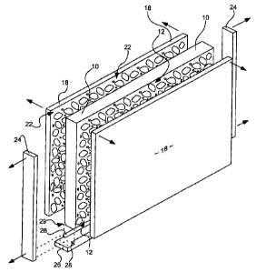
FIG. I is a perspective view of a vertical concrete panel formed in
accordance with an embodiment of the present invention, including a system of
associated concrete forms;
CA 02540511 2006-03-28
WO 2005/033442 PCT/US2004/032439
4
FIG. 2 is a side view of a system for vertically forming concrete panels in
accordance with an embodiment of the present invention;
FIG. 3 is a top, partially sectional view of the system of FIG. 2;
FIG. 4 is a more detailed, partially sectional side view of the system of FIG.
2;
FIG. 5A is a top, sectional view of a lower support gasket in accordance with
an
embodiment of the invention;
FIG. 5B is a side, sectional view of the lower support gasket of FIG. 5A;
FIG. 5C is an end, sectional view of the lower support gasket of FIG. 5A; and
FIG. 6 is a flowchart illustrating exemplary steps of a method for vertically
forming concrete panels in accordance with one aspect of the invention.
DETAILED DESCRIPTION
Reference will now be made to the exemplary embodiments illustrated in the
drawings, and specific language will be used herein to describe'the same. It
will
nevertheless be understood that no limitation of the scope of the invention is
thereby
intended. Alterations and further modifications of the inventive features
illustrated
herein, and additional applications of the principles of the inventions as
illustrated herein,
which would occur to one skilled in the relevant art and having possession of
this
disclosure, are to be considered within the scope of the invention.
Illustrated in FIG. 1 is an example of a vertical concrete panel 12 formed in
accordance with one aspect of the system described herein. As discussed in
more detail
below, various forms and structure such as side wall forms 18, end wall forms
24 and
lower support gasket 26 can be utilized to form the vertical concrete panel
12. Vertical
concrete panels such as that shown are used in a variety of applications,
including
residential and commercial fencing, sound wall applications, etc. Concrete
panels formed
in accordance with the present invention generally require little or no
maintenance,
provide superior strength, and can be relatively quickly assembled on the job
site into a
fence or other structure. Assembly of the panels into a fence structure is
generally
accomplished by installing or forming posts (not shown) which include slot
structure into
which the panels are disposed and held securely.
The concrete panel 10 can include a decorative pattern 12 formed in at least
one
side of the panel. In one embodiment of the invention, the decorative pattern
is
advantageously formed simultaneously in both sides of the panel. The
decorative pattern
CA 02540511 2006-03-28
WO 2005/033442 PCT/US2004/032439
can be formed to appear as a rock wall, a brick wall, or other such desirable
patterns. As
used herein, the term "decorative pattern" is understood to mean a pattern
applied to the
concrete panels, and may be decorative or functional, or both, in nature. In
addition to the
decorative pattern applied to the panel, the concrete panel can be stained or
dyed in a
5 particular color scheme to enhance the aesthetically pleasing appearance of
the panel.
The present system can be utilized to form concrete panels of a variety of
sizes.
For example, vertical concrete panels can be formed with a length of 12 feet,
a height of 6
or 8 feet, and a thickness of 4 inches. As described in more detail below,
panels of varied
width can be formed with the present system, including panels with 4, 5 or 6
inch widths.
The system can be adapted to provide a number of variously sized and shaped
vertical
concrete panels with minimal adjustments to the system being necessary to
effectuate
formation of differently sized panels.
Shown generally at 14 in FIG. 2 is a side view of a system and device in
accordance with the present invention that can be used to vertically form
concrete panels
such as that illustrated in at 10 in FIG. 1. The system can include a
generally rectangular
support frame assembly 15 (discussed in more detail below) which can receive
and
support a variety of concrete forms. The concrete fonns can include a pair of
opposing
side wall forms 18 which define side wall surfaces 21 of a mold cavity 20. The
side wall
forms are spaced a desired distance apart, corresponding to a desired
thickness of the
concrete panel to be formed. End wall forms (24 in FIGs. 1, 3 and 4) can be
positioned
adjacent the side wall forms to define end wall surfaces 25 of the mold
cavity. An
elongate lower support gasket 26 can define a bottom surface of the mold
cavity.
Thus, in this embodiment, the side wall forms 18, end wall forms 24 (not shown
in
FIG. 2) and lower support gaskets 26 are positioned to define a plurality of
vertical mold
cavities 20 that correspond to a concrete panel to be formed in each cavity.
As discussed
in further detail below, various tensioning and restraining devices can be
used to ensure
that the mold forms are not displaced by the introduction of uncured, or "wet"
concrete in
the mold cavity. Once each mold cavity is defined, and any retaining structure
has been
applied, wet concrete can be poured into each mold cavity. Vibrators or other
agitating
devices can be utilized when pouring the wet concrete to minimize voids and
ensure the
wet concrete fills each cavity to the extent desired.
After pouring, the concrete in the forms can be allowed to cure, after which
the
various retaining structure and forms can be removed. The cured panels can
then be
CA 02540511 2006-03-28
WO 2005/033442 PCT/US2004/032439
6
removed from the support frame assembly. In one aspect, the panels are removed
by
lifting equipment (not shown) which lifts each panel vertically away from the
support
frame assembly. The process can then be repeated a number of times to create a
number
of concrete panels. In the case where the proper concrete mix is used, the
system can
form panels on a one day cycle, that is, panels can be poured in the morning
and allowed
to cure through the night. The following morning, the cured panels can be
removed, the
forms can be reassembled, and the process begun again.
While four mold cavities 20 are defined in the system of FIG. 2, the present
invention can advantageously be used to vertically form any number of panels
by
providing fewer or more side wall 18 and end wall 24 forms and accompanying
lower
support gaskets 26. In this manner, the system can be tailored to specific
pour
requirements. For example, a specific number of panels with a=particular
decorative
pattern can be simultaneously poured, perhaps to correspond to a specific
length of fence
desired.
The side wall forms 18 can include an inverse decorative pattern 22 on one or
both sides of the side wall forms. As shown in FIG. 2, inverse decorative
patterns 22 can
be included on both sides of the side wall form 18d such that side wall form
18d defines
inside side wall surfaces of two adjacent mold cavities 20. In this manner,
only one side
wall form need be positioned between adjacent mold cavities. Alternatively,
two side
wall forms with inverse decorative patterns can be abutted back-to-back, with
the inverse
decorative patterns exposed on opposing sides of the back-to-back side wall
forms. Also,
each side wall form can include inverse decorative patterns that differ from
adjacent side
wall forms, or can include no inverse pattern, in the case that a "plain"
concrete panel is
to be formed.
The system can be used to simultaneously form a plurality of concrete panels
in a
manner that utilizes minimal floor space. To illustrate the space efficient
manner in
which concrete panels can be formed with the present invention, consider the
case in
which a concrete fence is to be formed from concrete panels having dimensions
of 6 feet
in height, 10 feet in length and 4 inches in width. Horizontally pouring a
sufficient
number of panels for a fence of 100 feet in length would require as much as
600 square
feet of floor space for the horizontal forms alone. In contrast, concrete
panels formed
vertically in accordance with the present invention can require about one-
tenth of that
amount, with as little as only 67 square feet of floor space being required.
Because the
CA 02540511 2006-03-28
WO 2005/033442 PCT/US2004/032439
7
present system laterally "stacks" vertical concrete mold cavities, optimal
space savings
can be obtained with the further advantage of vertically forming decorative
patterns on
both sides of the panels.
Support frame assembly 15 can include a variety of structures sufficient to
support
and contain the various forms, support gaskets, etc. Support frame assembly 15
can
include roller bar 17 onto which wheels 34 associated with the side wall forms
18 can be
disposed to allow the side wall forms to be easily rolled one way or another.
Handles 65,
or similar structure, can be included on the side wall forms to facilitate
easy movement of
the forms by operators.
By utilizing the integral support frame assembly 15, the present system can be
formed as an integral unit that can be moved from one location to another. In
this
manner, a series of mold forms can be created and secured, the forms can be
filled with
wet concrete, and the entire system can be lifted onto a truck and moved to a
job site.
The panels can cure in the area in which they were poured, or can cure while
in transit to
a job site, saving down-time otherwise necessary to ensure the panels are
cured prior to
shipping. Once cured, the concrete panels can be easily removed from the forms
and
assembled into a fence structure.
As shown by example in FIGs. 1 and 2, the side wall forms 18 can include
inverse
decorative patterns 22 disposed thereon. As wet concrete is poured into the
mold cavity,
the weight of the wet concrete ensures that the concrete fills in and around
the textured
surface of the inverse decorative pattern 22. After cure, the textured surface
appears in
the cured concrete panel as a decorative pattern (12 in FIG. 1), such as a
brick wall
appearance, a rock wall appearance, etc. Because the present invention
advantageously
forms concrete panels in a vertical orientation, the wet concrete can fill the
textured
surface of inverse decorative patterns on both sides of the mold cavity
equally well, in
contrast to horizontal mold systems which can generally only apply a well-
defined pattern
to a lower surface of the panel.
The inverse decorative pattern 22 can be of a variety of inverse patterns,
including
brick, rock, or other pseudo structure that provides the concrete panel with a
decorative or
functional advantage. The inverse decorative pattern can be formed on the side
wall
forms 18 by a number of methods. In one aspect, an inverse decorative pattern
is
provided on the side wall form by application of a polymer liner to the form.
The
polymer liner can be formed by preparing a "master" form over which an uncured
viscous
CA 02540511 2006-03-28
WO 2005/033442 PCT/US2004/032439
8
polymer can be poured. When the viscous polymer cures, the resulting polymer
liner can
be removed from the master form and bonded or otherwise attached to a steel
side wall
form. Once prepared, the side wall form can be used numerous times to apply
the
decorative pattern to a number of concrete panels poured in cavities defined
by the side
wall forms. By preparing many such polymer liners from the same master form,
multiple
panels having identical surfaces can be concurrently formed.
As perhaps best seen in FIG. 4, lower support gasket 26, which defines the
bottom
surface of the mold cavity, can include side walls 27 which can abut against
at least a
portion of an inside edge 21 of each side wall form 18 to provide a seal
between the lower
support gasket and side wall forms to retain concrete mixture within mold
cavity 60a,
60b. Also, side edge flanges 28 can extend upwardly from an upper surface 56
(best seen
in FIGs. 5A through 5C) of the lower support gasket 26. The upwardly extending
side
edge flanges can be configured to abut against at least a portion of an inside
21 each of
the side wall forms 18 to enhance the seal between the lower support gasket
and the side
wall forms. The lower support gasket, in combination with the side wall forms
and end
wall forms (end wall forms omitted from FIG. 2 for clarity), advantageously
limits or
prevents wet concrete from flowing outward from the mold cavity.
In past attempts to vertically pour concrete panels, problems have developed
in
that the wet concrete has crept outwardly from the mold cavity as the weight
of the wet
concrete forced the concrete under and away from the mold cavity. This has
resulted in a
wasteful and untidy operation, as wet concrete is not only lost but can cure
outside of the
forms, making the forms difficult to remove after curing. The present
invention
advantageously includes lower support gasket 26 having upwardly extending side
edge
flanges 28 which cooperatively serve the dual purpose of defining the lower
surface of the
mold cavity and retaining wet concrete within the mold cavity. In addition,
the side edge
flanges can form a chamfered edge (29 in FIG. 1) on the cured concrete panel,
leading to
a more attractive and less jagged top surface of the vertical panel (in this
aspect, the panel
is formed upside down in the mold form, with the top of the cured panel
disposed at the
bottom of the form).
The system 14 is shown in top view in FIG. 3, looking downward into the mold
cavities 20a and 20b. In this view, the leftmost mold cavity 20a is shown
prior to the
introduction of wet concrete into the mold, and lower support gasket 26a
having side edge
flanges 28a and 28b is visible at the bottom of the mold cavity 20a. In
contrast, rightmost
CA 02540511 2006-03-28
WO 2005/033442 PCT/US2004/032439
9
cavity 20b is filled with concrete mixture 30, such that lower support gasket
26b is only
partially visible. End wall form 24a defines the end wall surface 25 of the
mold cavity
20a, and can be held in place by retaining structure 32 associated with side
wall forms 18.
In this embodiment, the side wall forms 18 are movably coupled to support
frame
assembly 15 by rail 17 and can include wheels or rollers 34 which allow the
side wall
forms to move relative to the support frame.
Thus, the mold cavities 20 can be defined by moveable concrete forms. As an
example of the present invention in use, first side wall form 18a can be
positioned in a
desired location within the support frame assembly 15. Lower support gasket
26a can be
positioned adjacent the side wall form 18a, with side edge flange 28a abutting
against the
side wall form 18a. End wall form 24a can then be placed within the retaining
structure
32a associated with side wall form 18a. Side wall form l 8b can then be moved
into
position such that end wall form 24a is oriented within retaining structure
32b associated
with side wall form 18b. In this manner, side edge flange 28b is abutting
against side
wall form 18b and end wall form 24a is secured in place between side wall
forms 18a and
18b by retaining structure 32a and 32b.
If desired, additional side wall form 18c can be similarly positioned with end
wall
form 24b and lower support gasket 26b (primarily hidden by concrete 30)
forming an end
and a bottom, respectively, of mold cavity 20b. The width of the concrete
panels thus
formed can be easily altered by the use of alternate end wall forms 24 and
lower support
gaskets 26. If a wider panel is required, wider end wall forms and support
gaskets can be
utilized. If a panel with a narrower width is required, narrower end wall
forms and
support gaskets can be used.
Once each end wall form, side wall forin and lower support gasket are
positioned,
the forms can be restrained in position in a number of manners. Due to the
substantial
weight of uncured concrete, the various forms will tend to move outwardly from
the
defined mold cavity upon introduction of wet concrete into the cavity. As
discussed
above, end wall forms 24 can be secured in place by retaining structure 32.
Further, as
illustrated in FIG. 2, side wall tensioning members 40 can be coupled to the
various side
wall forms to restrain the side wall forms from moving in reaction to forces
introduced by
wet concrete poured in the mold cavity.
The tensioning members 40 can be a variety of those known in the art, and can
include threaded end 42 which can be secured in place by nut 44. An opposing
threaded
CA 02540511 2006-03-28
WO 2005/033442 PCT/US2004/032439
end 46 can similarly be secured by nut 48. Each of the nuts 44, 48 can be
tightened to
tension the side wall forms together. To provide for variation in the number
of mold
cavities formed, threaded end 46 can include a length of threads that allow
nut 48 to be
attached in a variety of positions to facilitate tensioning of a varying
number of concrete
5 forms.
As shown in FIG. 2, the tensioning members 40 can be disposed outside of the
mold cavity so as to retain the side wall forms in position without displacing
the wet
concrete in the mold cavity. In this manner, the forms are securely held in
position
without adversely affecting the finished panel by introducing foreign matter
into the wet
10 concrete and without leaving cavities in the concrete, as has been done in
previous
methods. In this manner, the concrete forms are maintained securely in place
prior to
curing of the concrete without compromising either the structural integrity or
aesthetic
appearance of the finished concrete panel.
FIG. 3 illustrates an aspect of the invention in which cured concrete panels
can be
easily removed from the system upon reaching sufficient cure. In this
embodiment,
threaded reinforcing member 70, which can be formed from or attached to
material
commonly known as "rebar," can be suspended within the mold cavity. An
elongate strap
or bar 66 can be placed over the rebar of each cavity and secured with nut 68.
Wet
concrete can be poured over and around the strap to fill the mold cavity. Once
the panels
have cured, nuts 68 and strap 66 can be removed, and the side wall forms can
be rolled
away from the cured panel. Reinforcing member 70, which has now been cured
within
the panel, can be grasped with lifting equipment and the panel can be
vertically removed
from the support frame assembly (not shown in FIG. 3). Thus, the strap 66 is
generally
the last structure applied to the system prior to pour and the first structure
removed from
the system after panel cure.
The lower support gasket 26 can be formed of a variety of materials, and in
one
embodiment is formed of a substantially compliant polymer, such as 2070 SX
polymer.
One advantage of this feature is illustrated in FIG. 4, wherein the leftmost
mold cavity
60a is empty (and with which no end wall form is shown) and the rightmost mold
cavity
60b contains uncured concrete 62. As the uncured concrete fills mold cavity
60b, the
frictional forces between the concrete and the end wall form 24 cooperate to
pull the end
wall form snugly against the lower support gasket. As shown at 63, the polymer
material
CA 02540511 2006-03-28
WO 2005/033442 PCT/US2004/032439
11
of the support gasket can at least partially compress beneath the weight of
the end wall
form to provide a more secure seal between the end wall form and the support
gasket.
Also shown in FIG. 4 is a lower support platform 64 over which can be disposed
the various concrete forms utilized in the present system. In this aspect, the
lower support
gasket 26 can be slidably disposed on the lower support platform 64 to allow
the support
gasket to be easily and accurately associated with a set of side wall forms
18. When
using a system including the sliding lower support gasket, an operator can
first slidably
dispose the lower support gasket 26 on the lower support platform 64. A first
side wall
form can then be positioned adjacent the lower support gasket, and, as the
lower support
gasket can slide, can move the lower support gasket into a desired position. A
second
side wall form can then be positioned adjacent the remaining side of the
support gasket
and abutted against the gasket to "sandwich" the gasket between the side wall
forms. By
utilizing the sliding, or floating, lower support gasket, the positions of the
side wall forms
are not dictated by the lower support gasket, and can be positioned in a
variety of
locations within the support frame assembly 15 (not shown in FIG. 4).
Various features of the lower support gasket 26 are illustrated in FIGs. 5A
through
5C, which correspond to side, top and end views, respectively, of the support
gasket. The
lower support gasket can include upper surface 56, which at least partially
defines a
bottom surface of the mold cavity. The lower support gasket can include a pair
of side
edge flanges 28 which extend upwardly from upper surface 56 of the support
gasket 26
and can be configured to abut against each side wall form (not shown in FIGS.
5A
through 5C). As discussed above, the support gasket can be formed of a
substantially
compliant polymer which can provide an effective seal between the gasket and
each of
the end wall forms 24 and side wall forms (not shown in FIGs. 5A through 5C).
As the
mold cavity in which the lower support gasket is disposed fills with wet
concrete, the side
edge flanges are allowed to slightly bend outwardly to form a seal that
increases in
effectiveness with the addition of more wet concrete. Thus, wet concrete is
held within
the mold cavity even when larger panels are poured, panels that may generally
require
greater amounts of wet concrete.
The lower support gasket can include reinforcing structure 50 which can
increase
a load-bearing capacity of the support gasket. In the embodiment illustrated
in FIG. 5C,
the reinforcing structure is disposed within the lower support gasket to
provide support to
the gasket without interfering with the concrete pouring process. In this
embodiment, the
CA 02540511 2006-03-28
WO 2005/033442 PCT/US2004/032439
12
reinforcing structure includes a pair of substantially rectangularly-shaped
steel tubes 51.
The tubes can minimize the amount of compliant polymer that is needed, such
that
sufficient polymer is present to seal the mold cavity, but is prevented from
deforming to
an undesirable level by the reinforcing structure. In addition to the
embodiment shown,
the reinforcing structure can be disposed on, over, or adjacent to the support
gasket to
provide reinforcement to the support gasket.
As shown at 28c in cut-away view in FIG. 5C, in one aspect of the invention,
side
edge flange 28c can include a substantially triangular cross section. While it
has been
found that a triangular cross section provides a superior seal against the
side wall forms
(not shown in FIGs. 5A through 5C), other cross sections can also be utilized.
In one
aspect of the invention, side edge flange 28d can include a cross-section with
a greatest
width Wl nearest the upper surface 56 of lower support gasket 26 and a
narrowest width
W2 at a point furthest above the upper surface of the lower support gasket.
As shown in FIGs. 5A and 5B, in one aspect of the invention the side edge
flanges
28 extend upwardly from the upper surface 56 of support gasket 26 along only a
central
portion 52 of a length of the support gasket, and not at terminal portions 54
of the support
gasket. In this manner, the lower support gasket can provide optimal sealing
contact with
the side wall forms 18 (not shown in FIGs. 5A through 5C) while providing a
substantially flat contact surface for the end wall forms 24. This feature can
be
appreciated by viewing FIG. 5B, where the side edge flanges do not extend into
the
terminal portions 54 of the lower support gasket which is contacted by end
wall forms 24.
In this manner, a superior seal is provided between the lower support gasket
and the end
wall forms.
A method for utilizing the system described above is illustrated in flow chart
form
in FIG. 6. The method can include the steps of. positioning 72 a lower support
gasket on
a lower support platform, the lower support gasket having two opposing ends
and two
opposing sides; vertically positioning 74 and abutting two opposing end wall
forms at
opposing ends of the support gasket; vertically positioning 76 front and rear
opposing
side wall forms at opposing front and rear sides of the support gasket to
thereby define a
mold cavity into which an uncured concrete mixture can be poured; forming 78 a
seal
between the side wall forms and the lower support gasket by abutting front and
rear edges
of the lower support gasket against at least a portion of an interior side of
the opposing
side wall forms; and supporting 80 each of the side wall forms and end wall
forms to
CA 02540511 2006-03-28
WO 2005/033442 PCT/US2004/032439
13
resist expansion forces introduced when pouring the uncured concrete mixture
into the
mold cavity.
It is to be understood that the above-referenced arrangements are illustrative
of the
application for the principles of the present invention. Numerous
modifications and
alternative arrangements can be devised without departing from the spirit and
scope of the
present invention while the present invention has been shown in the drawings
and
described above in connection with the exemplary erabodiments(s) of the
invention. It
will be apparent to those of ordinary skill in the art that numerous
modifications can be
made without departing from the principles and concepts of the invention as
set forth in
the claims.