Note: Descriptions are shown in the official language in which they were submitted.
CA 02540566 2006-03-02
WO 2005/023354 PCT/GR2004/000045
1
Endotherapy catheter
The proposed invention is a catheter that can be used
for infusion of drugs and nutrients with concurrent
aspiration of biological material, in human and, or,
animal tissue and, or, body cavity, and, or, neoplastic
tissue and, or, pathological liquid accumulations in the
body.
There are many kinds of catheters which are used for
fluid infusion and aspiration in a clinical or
preclinical setting.
Traditionally, the catheter's tip that is inserted in
biological material, is called "distal" and the tip that
stays outside is called "proximal".
Most of existing catheters have a single lumen - tube
and through this lumen - tube the user - doctor, nurse,
scientist or laboratory personnel - can alternatively
infuse or aspirate liquids.
For example, in a clinical setting, the common
25_ intravenous catheter either aspirates blood samples -
CA 02540566 2006-03-02
WO 2005/023354 PCT/GR2004/000045
2
usually immediately after it's insertion to the vein -
or infuses solutions of drugs and, or, nutrients -
usually for many hours or days following insertion.
These catheters can infuse or aspirate large quantities
of liquids, but they cannot do it concurrently in order
to have a constant exchange of drugs and nutrients with
pathological liquid accumulations.
That means that during the infusion phase, the tissue
increases in volume and this could be dangerous or even
fatal in certain cases (for example in an already
suffering from oedema brain).
There are also catheters with multiple lumen - tubes,
which can concurrently infuse and aspirate liquids.
For example, the microdialysis catheter after it's
introduction to a human or animal tissue, is
continuously perfused with liquid solutions from a pump
connected to its proximal tip. The catheter consists of
two concentric lumens - tubes, that are covered at their
distal tip by a membrane. Usually the central lumen -
tube is the efferent and the peripheral lumen - tube is
the afferent part of the catheter. Part of the perfused
liquid is infused to the tissue through the catheter's
membrane at its distal end, and extracellular tissue
CA 02540566 2006-03-02
WO 2005/023354 PCT/GR2004/000045
3
fluid is aspirated through the same membrane and the
efferent lumen - tube.
Microdialysis catheters and similar to them catheters
though, were designed for tissue monitoring, and the
above described concurrent infusion and aspiration takes
place at a microliters flow rate. For therapeutic
applications we need greater liquid exchange rate.
Additionally, a common problem of all kinds of existing
catheters for biological fluids, is their blockage, due
to corking of biological material into their lumen's
aspirating tip, or coverage of their liquid exchange
membrane (like microdialysis catheter's membrane) from
organic substances (mostly proteins).
The proposed endotherapy catheter infuses and aspirates,
even great quantities of liquids, concurrently, at a
wide range of flow rates, without any blockage problems.
It consists of two concentrical lumens - tubes,
connected properly to infusion and aspiration devices at
their proximal tip, and having a filter or membrane or
grid or mesh cage covering their distal tip, which
contains an hydrodynamically moving device for
concurrent infusion and aspiration.
CA 02540566 2006-03-02
WO 2005/023354 PCT/GR2004/000045
4
The infusing lumen - tube is appropriately connected to
the device that irrigates the surrounding the catheter
space, while simultaneously propels with its movement
the aspiration through the other tube.
The endotherapy catheter utilizes the circulating
fluid's shear forces to remove any biological material
that blocks the catheter's distal tip.
The attached drawings represent two of the many possible
variations of the endotherapy catheter.
The numbers and letters of the drawings refer to:
1) aspiration outer lumen - tube
2) infusion inner lumen - tube
3) moving - rotating device
4) liquid exchange surface
5) moving - rotating device's port - housing for
stator
6) stator
7) intermediate space between stator and moving -
rotating device
8) moving - rotating device's ports - openings
9) moving - rotating device's tip
10) housing for the moving - rotating device°s tip
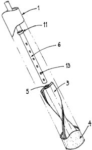
11) inner lumen - tube's travel limiter
CA 02540566 2006-03-02
WO 2005/023354 PCT/GR2004/000045
12) centering supports
13) stator's through holes - openings
14) infusion device
15) aspiration device and, or, collection tank and,
5 or, analysis device
16) catheter bifurcation
17) proximal face of the moving - rotating device
A) Direction of movement - rotation of the moving -
rotating device
B) Direction of infused liquid
C) Direction of aspirated liquid
The endotherapy catheter has an infusion inner lumen -
tube (2) and an aspiration outer lumen - tube (1).
The fluid is supplied by an infusion device (14) or any
liquid container that has positive pressure, relatively
to the pressure of the surrounding the catheter's tip
tissue, while the returning fluid is collected by a
negative pressure pump, or any liquid container with
negative pressure, relatively to the pressure of the
surrounding the catheter's tip tissue.
The endotherapy catheter has a bifurcation part (16), in
order to split the two opposite flows in two different
lumens - tubes, as shown in drawing 1.
CA 02540566 2006-03-02
WO 2005/023354 PCT/GR2004/000045
6
The distal end of the outer lumen - tube holds an
exchange surface (4), that can be a filter or membrane
or grid or mesh cage.
Fluid, which can vary from distilled water to nutrient
solutions with drugs, that is supplied through the inner
lumen - tube (2), according to arrow B, reaches the
distal end of the catheter, where substance exchange
occurs between the infused fluid and substances
contained in the surrounding tissue's extracellular
fluid; the fluid returns to an aspiration device and,
or, collection tank and, or, measurement system (15),
according to arrow C.
In order to remove organic substances that are built up
on the exchange surface, and consequently block the
catheter, a fluid jet, receiving its supply from the
inner lumen - tube (2), is dispersed against the liquid
exchange surface's inner wall (4), via the moving -
rotating device's ports (8), as shown in drawings 2, 4.
The jet propels the rotation of the moving - rotating
device (3) according to arrow A.
Drawings 2,3 and 4 depict two of the many possible
variations of the same concept. In the first variation,
shown in drawings 2,3, the moving - rotating device has
CA 02540566 2006-03-02
WO 2005/023354 PCT/GR2004/000045
7
a hollow twisted plate shape, while in the second
variation, shown in drawing 4, the moving - rotating
device resembles a twin helix chain.
As shown in drawing 3, the moving - rotating device (3)
holds a port (S) that serves as a fluid supply inlet,
but also as a housing for the stator (6) , which is the
distal end of the inner lumen - tube (2).
The stator (6) may hold, circumferentially and on its
end, through holes -.openings (13), to allow fluid
outlet from the inner lumen - tube (2) to the
intermediate space (7) between stator and moving -
rotating device. This intermediate space is created
since the stator's (6) outer diameter is slightly
smaller than the moving - rotating device's port (S)
diameter, and serves as a mass transfer subspace and a
friction eliminator, since it follows a slide bearing
function principal.
The moving - rotating device (3) may have an helical
shape and hold ports - openings (8), that take fluid
from the intermediate space between stator and moving -
rotating device (7), and redirect it against the
exchange surface walls (4), with a direction angle other
than the radial, so that a rotational propulsion is
achieved, as shoom in dra~~ings 2, 4 0
CA 02540566 2006-03-02
WO 2005/023354 PCT/GR2004/000045
8
The angle is selected based on a trade-off between the
device's (3) rotation frequency and the shear stress on
the exchange surface walls.
That is, a rather radial direction biased angle
S selection would result on fewer rotations per given time
but higher shear stresses, while a rather
circumferential direction biased angle selection would
result on more rotations per given time but lower shear
stresses.
Therefore, the moving - rotating device (3) not only
removes the organic remains that block the exchange
surface (4), but is also responsible for its movement -
rotation.
As shown in drawings 2, 4, the moving - rotating device
(3) may have an overall or particular helical shape with
a spin direction such that, due to the jet-induced
rotation, its proximal face (17) pushes fluid
proximally, forcing its return to the extracorporeal
collecting equipment.
This is particularly useful to avoid stagnation of the
organic substances that were exchanged through the
filter or membrane or grid or mesh cage, by forcing
their removal.
CA 02540566 2006-03-02
WO 2005/023354 PCT/GR2004/000045
9
As shown in drawings 2, 4, the tip (9) of the moving -
rotating device could be such that it supports the
device in place inside the outer tube (1) and at the
same time allows for relative movement - rotation.
To facilitate that, the lower part of the outer tube may
hold a recess (10), in order to house the tip (9) of the
moving - rotating device (3).
In addition, a travel limiter (11) can be present at an
appropriate level of the inner tube, to assure operation
under all inclinations.
The inner tube (2) may be centered coaxially to the
outer tube (1) to ensure evenness in function. To
achieve that, one or more centering supports (12) can be
placed between the inner and outer tubes, just
proximally to the moving - rotating device (3) level.
The catheter may have an overall flexibility in order
not to present resistance during any movement of the
implanted tissue relatively to its, relatively stable,
exit point, however the distal end has to be fairly
rigid, to ensure that the moving - rotating part can
work properly.
So, the materials are selected appropriately, to offer
relative stiffness at the distal end of the inner and
CA 02540566 2006-03-02
WO 2005/023354 PCT/GR2004/000045
outer tube, while more compliant materials may be
selected for the rest of the catheter.
For certain clinical and laboratory applications though,
the whole catheter can be rigid.
5 The material of the catheter should also be in
conformity to the norms and regulations existing for
clinical and laboratory catheters, including
biocompatibility issues etc.
15
25