Note: Descriptions are shown in the official language in which they were submitted.
CA 02540929 2006-03-30
WO 2005/118406 PCT/US2005/014264
APPLYING LABELS ON SURFACES OF VARIOUS ORIENTATIONS
BACKGROUND OF THE INVENTION
Field of the Invention
The present invention relates generally to the placement or reading of
labels, markings, or other items on parcels or other items being conveyed
along a
conveying path.
Description of Related Art
The prior art includes many different methods and apparatuses for applying
labels to parcels or other items to parcels as they pass along a conveying
path.
However, there are always needs in the art and improvements needed thereto.
BRIEF SUMMARY OF THE INVENTION
The present invention overcomes the deficiencies of the prior art by
providing a method and apparatus for attaching labels (including bar or other
coded labels and including but not limited to RFID labels) or other articles
to
parcels or other items.
Generally described, the invention is directed towards a method and
apparatus for transferring labels or other items to an outer surface of
parcels being
conveyed along a conveying path, the path having a width and defined by a
conveying surface having a portion lying in a conveying plane, the parcels
having
horizontal and vertical surfaces, the apparatus comprising a relatively
stationary
frame, a first turntable assembly, the first turntable assembly itself
comprising a
first stationary turntable portion attached relative to the stationary frame,
and a first
rotating tunitable portion rotatably attached relative to the first stationary
turntable
portion such that the first rotating turntable portion can rotate about a
first turntable
axis relative to the first stationary turntable portion and the frame, a
second
turntable assembly, the second turntable assembly itself comprising a second
stationary turntable portion attached relative to the stationary frame, and a
second
rotating turntable portion rotatably attached relative to the second
stationary
turntable portion such that the second rotating turntable portion can rotate
about a
second turntable axis relative to the second stationary turntable portion and
the
CA 02540929 2006-03-30
WO 2005/118406 PCT/US2005/014264
frame, a first elongate arm mounted relative to the first rotating turntable
portion so
as to allow for linear movement of the first elongate arm relative to the
first
rotating turntable portion along a first linear path substantially parallel to
the
longitudinal axis of the first elongate arm, yet the first elongate arm is
also allowed
to rotate about the first turntable axis along with the first rotating
turntable portion,
a second elongate arm mounted relative to the second rotating turntable
portion so
as to allow for linear movement of the second elongate arm relative to the
second
rotating turntable portion along a second linear path substantially parallel
to the
longitudinal axis of the second elongate arm, yet the second elongate arm is
also
allowed to rotate about the second turntable axis along with the second
rotating
turntable portion, a pivoting connection intermediate and connecting the first
and
second elongate anns, a first arm drive means to provide a force sufficient to
cause
the first elongate arm to move along the first linear path relative to the
first rotating
turntable portion, a second arm drive means to provide a force sufficient to
cause
the second elongate arm to move along the second linear path relative to the
second rotating turntable portion, and a label application head attached
relative to
one of the first and second elongate arms, such that the label application
head may
be moved to various locations across the width of the conveyor path and at
different heights relative to the conveyor surface, and the label application
head
may be manipulated to dispense labels or other items upon surfaces of parcels
being conveyed along the conveying surface.
The invention is further directed towards a method for transferring labels or
other items to an outer surface of parcels being conveyed along a conveying
path,
said path having a width and defined by a conveying surface having a portion
lying
in a conveying plane, said parcels having horizontal and vertical surfaces,
said
method comprising the steps of providing a relatively stationary frame,
providing a
first turntable assembly, said first turntable assembly itself comprising a
first
stationary turntable portion attached relative to said stationary frame, and a
first
rotating turntable portion rotatably attached relative to said first
stationary
turntable portion such that said first rotating turntable portion can rotate
about a
first turntable axis relative to said first stationary turntable portion and
said frame,
providing a second turntable assembly, said second turntable assembly itself
comprising a second stationary turntable portion attached relative to said
stationary
frame, and a second rotating turntable portion rotatably attached relative to
said
-2-
CA 02540929 2006-03-30
WO 2005/118406 PCT/US2005/014264
second stationary turntable portion such that said second rotating turntable
portion
can rotate about a second turntable axis relative to said second stationary
turntable
portion and said frame, providing a first elongate arm mounted relative to
said first
rotating turntable portion so as to allow for linear movement of said first
elongate
arm relative to said first rotating turntable portion along a first linear
path
substantially parallel to the longitudinal axis of said first elongate arm,
yet said
first elongate arm is also allowed to rotate about said first turntable axis
along with
said first rotating turntable portion, providing a second elongate arm mounted
relative to said second rotating turntable portion so as to allow for linear
movement
of said second elongate arm relative to said second rotating turntable portion
along
a second linear path substantially parallel to the longitudinal axis of said
second
elongate arm, yet said second elongate arm is also allowed to rotate about
said
second turntable axis along with said second rotating turntable portion,
providing a
pivoting connection intermediate and connecting said first and second elongate
arms, providing a first arm drive means to provide a force sufficient to cause
said
first elongate arm to move along said first linear path relative to said first
rotating
turntable portion, providing a second arm drive means to provide a force
sufficient
to cause said second elongate arm to move along said second linear path
relative to
said second rotating turntable portion, and providing a label application head
pivotably attached relative to one of said first and second elongate arms,
manipulating said label application head about said label head axis, and at
the same
time operating first and second arm drive means so as to cause said first and
second arm assemblies to move along said first and second linear paths,
respectively, relative to said first and second rotating turntable portions,
respectively, moving said label application head to various locations across
the
width of said conveyor path and at different heights relative to said conveyor
surface, and manipulating said label application head to suitably different
orientations to dispense labels or other items upon both horizontal and
vertical
surfaces of parcels being conveyed along said conveying surface.
Therefore, it is an object of the present invention to provide an improved
method and apparatus for applying labels or other items to separate items.
It is a further object of the present invention to provide an improved
method and apparatus for applying adhesive labels to items on a conveyor.
-3-
CA 02540929 2006-03-30
WO 2005/118406 PCT/US2005/014264
It is a further object of the present invention to provide an improved
method and apparatus for applying labels including RFID features to items
having
horizontal or vertical supporting surfaces.
It is a further object of the present invention to provide an improved
method and apparatus for applying labels or other items to parcels on a
conveyor,
such that the label or other item can be placed on both vertical and
horizontal
surfaces of the parcels.
It is a further object of the present invention to provide a method and
apparatus for providing labels or other items on items which is reliable.
It is a further object of the present invention to provide a method and
apparatus for providing labels or other items on items which is efficient.
It is a further object of the present invention to provide a method and
apparatus for providing labels or other items on items which is versatile.
It is a further object of the present invention to provide a method and
apparatus for providing labels or other items on items which is adjustable.
It is a further object of the present invention to provide a method and
apparatus for positioning an item proximate conveyors on which packages are
transported.
It is a further object of the present invention to provide a method and
apparatus for positioning a scanner or other reading device relative to
parcels or
other items as they are conveyed thereby.
Otlier objects, features, and advantages of the present invention will
become apparent upon reading the following detailed description of the
preferred
embodiment of the invention when taken in conjunction with the drawing and the
appended claims.
BRIEF DESCRIPTION OF THE SEVERAL VIEWS OF THE DRAWINGS
Having thus described the invention in general terms, reference will now be
made to the accompanying drawings, which are not necessarily drawn to scale,
and
wherein:
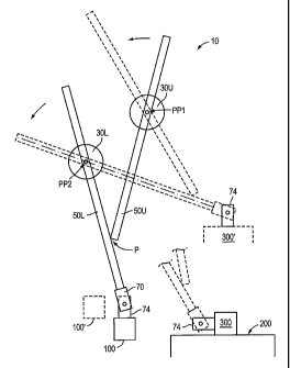
Fig. 1 is an illustrative view illustrating the apparatus 10 in operation.
Multiple positions of a label application member 74 (being part of a label
application head assembly 70) are shown, both in association with a label
printer/supplier 100 (also in an alternate location 100), as well as in
positions for
-4-
CA 02540929 2007-09-10
depositing labels on parcels 300, 300', which are positioned atop a conveyor
200
or other supporting surface. Upper and lower rotating turntable assemblies
30U,
30L, are shown which support upper and lower arm assemblies 50U, 50L,
respectively, to allow them to pivot about pivot points PP1, PP2, respectively
while still being able to move linearly along their length relative to the
rotating part
of the turntable. The lower ends of the upper and lower upper arm assemblies
50U, 50L are pivotably attached at a pivot location "P", said pivot location
being
not at the end but proximate the end of the lower ann assembly 50L, said
pivoting
connection being along an axis being substantially horizontal and parallel to
the
conveyor direction.
F18. 2 is a partial pictorial view of the label application head assembly 70,
attached to the lower end of a lower arm main frame element 51L (being part of
the upper arm assembly). The label application head assembly 70 is rigidly
attached relative to the lower end of the lower arm assembly 50L. The label
application head assembly 70 includes the following elements: a frame 71, a
servo
motor 73, a label application member 74 (having a fan side opening 74-F shown
in
Fig. 2 and a label side opening 74-L shown later in Fig. 7A), an applicator
position
endless drive belt 75, various control wires and air supply tubes 78, and an
optional
home position indicator (laser) 79. The laser 79, which emits a laser beam
79B,
which can be pointed towards a stationery target T, for "homing" purposes. The
servo motor 73 rotatably drives a drive pulley (seen later in Figs. 7A and 7B
as
73P) about an axis 73A. The label application member 74 is pivotably mounted
relative to the frame 71 of the label applicator head assembly 70 about an
axis
74A, and picks up and subsequently dispenses labels as discussed later in this
application.
Fig_3 is a partial pictorial view of a portion of the apparatus 10, namely =
the
portion which includes a support frame 20 (having typical fratne elements 21),
a
breakaway support plate 22, upper and lower turntable assemblies 30U, 30L,
upper
and lower arm assemblies 50U, 50L, and upper and lower arm assembly drive
motors 61U, 61L. Also shown are the rotating outer turntable portion 34U of
the
upper turntable assembly 30U, the rotating outer turntable portion 34L of the
lower
turntable assembly 30L, the upper and lower linear bearing assemblies 36U,
36L,
respectively, and upper and lower gearbox assemblies 62U, 62L, respectively.
It
should be understood that the upper and lower gearbox assemblies could be
located
-5-
CA 02540929 2007-09-10
on either side of the upper and lower linear bearing assemblies 36U, 36L; Fig.
4
shows an alternate layout.
Fi~. 4 is an illustrative view illustrating the interaction of the upper and
lower turntable assemblies 30U, 30L and the upper and lower arm assemblies
50U,
50L (each of which includes a respective frame elements (51U, 51L). Typical
turntable bearings 32U, 32L, are shown, which are the bearings intermediate
the
stationary inner turntable portions and the rotating outer turntable portions
discussed later in this application. Also shown illustratively are the lower
linear
bearing assembly 36L (in phantom), and the lower gearbox assembly 62L (also in
phantom). Also shown is the upper motor 61U (in phantom), two upper idler
gears
65U, and an upper drive cog 64U. Finally, a portion of the upper cogged belt
53U
is shown, although the ends of the belt are not shown in their anchored
locations
attached to the upper arm frame element 51U as known in the art.
Figs. 5A and 5B are illustrative figures, illustrating the pivoting connection
of a portion of the apparatus 10 about a pivot point PP. Shown is a breakaway
support plate 22 pivotably mounted relative to the support frame 20 about a
pivot
point PP. Illustratively are also shown the upper and lower turntable
assemblies
30U, 30L, which are attached to the breakaway support plate 22. Lower arm
assembly 50L is shown, although the upper anm assembly is understood to be
behind the lower arm assembly but is not shown. It should also be understood
that
the lower arm assembly is shown in simplified form, as various control lines,
etc
are in reality attached to and extended therefrom. Furthermore, the motors are
not
shown. Axes 32UA and 32LA are shown to illustrate the axes about which the
upper and lower arm assemblies, respectively, are allowed to rotate. If an
element
such as a box moving on a conveyor contacts the label application head
assembly
70, the apparatus pivots from the position shown in Fig. SA to the position
shown
in Fig. 5B. A spring 25 provides a return feature as needed.
Fig. 6 is a side illustrative view showing the manner of support provided
the upper arm assembly 50U relative to the frame 20 having typical frame
elements
21. This figure shows the breakaway support plate 22 pivotably attached at
pivot
point PP relative to the frame 20, with a presence sensor 27 being used to
provide
a control indication that the breakaway support plate 22 is in the position of
Fig. 6, or alternately in the position of Fig. 5B. The return spring is not
shown.
The inner and outer turntable portions 31U, 34U for the upper tuintable
assembly
-6-
CA 02540929 2007-09-10
30U are shown, as are the inner and outer turntable portions 31L, 34L for the
lower turntable assembly 30L shown. Also shown are the linear bearings 37U
that
provide for the linear movement between the upper ann assembly 50U and
rotating
outer turntable portions 34U of the upper turntable assembly 30U.
Figs. 7A and 7B are illustrative views, illustrating the operation and
interaction of the servo motor 73, the drive belt 75, and the label
application
member pulley 74P. Fig. 7A shows the label application member 74 oriented with
its active side (a.k.a. the label side opening 74-L) in a "down" orientation,
such as
would be used in picking up a label. Fig. 7B shows the member 74 rotated 90
in
order to position it so that a label can be applied to a vertical surface,
such as the
vertical surface of a package. It should be understood that range of motion of
the
member 74 is greater than 90 .
Figure 8 is a graph showing the rotational velocity of various elements of
the invention over time. Particularly, the graph shows the rotational velocity
of the
motor 61U over time, the rotational velocity of the motor 61L over time, and
the
rotational velocity of the label application assembly's servo motor 73 (two
exemplary situations are shown).
Figure 9 is a schematic view illustrating the operable connection and
association between the control apparatus 120 (shown in one
example as including a PLC) the motors 61U, 61L, and their associated servo
amps
61U-S, 61L-S, the label applicator drive motor 73, the label printer 100, and
the
breakaway plate presence sensor 27. Also shown is a "Head in Nest" sensor 101,
which is a sensor that recognizes when the label application head assembly 70
is in
its "nest" which is the used to indicate that it is ready to receive labels.
Also shown
is a "Labels in Stock" sensor 102, which is configured to provide a signal to
the
control apparatus 120 that a certain pre-determined number of labels are left
in
the printer. This can be used for planning purposes; in one embodiment when
the label printer 100 is out of labels, it sends a signal to the control
apparatus,
but by this time the system has to be stopped. Also shown is a "label at head"
sensor 103, which allows the system to know that the label application member
74 has received a new label from the printer. Also shown is a "Printer
Position"
sensor 104, which provides an indication to the overall system that the
printer
is in its operating position. This is to be distinguished from a service
position
which may be used when the printer is being serviced or provided with Label
Stock. Also shown is a "Nest Plate" sensor 105,
-7-
CA 02540929 2007-09-10
which is a sensor operably associated with a plate that acts as a last resort
damage
prevention device to prevent the label application head assembly 70 from
colliding
with the printer or other devices. This is to address an emergency condition
that is
otherwise to be avoided, such as in the case of if the label applicator has
gone too
far.
Figure 10 is an illustrative view of the transverse cross section of an upper
arm main frame element 51U, as it is retained for linear movement relative to
a
upper linear bearing assembly 36U. The upper linear bearing assembly 36U is
attached to the rotating outer turntable portion 34U. The upper cogged belt
53U is
also shown in transverse cross section. However it should be understood that
the
upper cogged belt 53U could be on either side of the upper arm frame
element 51U. Bearings as known in the art exist but are not shown between the
upper arm frame element 51U and the T-shaped spinelike portion of the
upper linear bearing assembly 36U. However it may readily be understood that
bearings may be provided therebetween, typically held by races fixed to the
upper linear bearing assembly 36U, to allow for the bearings (not shown) to
roll
on the upper arm frame element 51U and to facilitate linear movement of the
upper an-n frame element 51U relative to the upper linear bearing assembly
36U,
along an axis substantially normal to the sheet of paper bearing the drawing.
Other linear bearing configurations could be used without departing from the
spirit and scope of the present invention.
DETAILED DESCRIPTION OF THE INVENTION
The present inventions now will be described more fully hereinafler with
reference to the accompanying drawings, in which some, but not all embodiments
of the invention are shown. Indeed, these inventions may be embodied in many
different forms and should not be construed as limited to the embodiments set
forth
herein; rather, these embodiments are provided so that this disclosure will
satisfy
applicable legal requirements. Like numbers refer to like elements throughout.
Many modifications and other embodiments of the inventions set forth
herein will come to mind to one skilled in the art to which these inventions
pertain
having the benefit of the teachings presented in the foregoing descriptions
and the
associated drawings. Therefore, it is to be understood that the inventions are
not to
be limited to the specific embodiments disclosed and that modifications and
other
embodiments are intended to be included within the scope of the appended
claims.
-8-
CA 02540929 2007-09-10
Although specific terms are employed herein, they are used in a generic and
descriptive sense only and not for purposes of limitation.
General Construction and Operation
The apparatus 10 according to the present invention is configured to apply
labels such as 5 (see Figs. 7A and 7B) to parcels 300 moving along a conveyor
200.
Referring generally to all the figures, the apparatus 10 of the present
invention includes a support frame 20, a pair of turntable assemblies 30U,
30L, a
con-esponding pair of arm assemblies 50U, 50L, similarly corresponding arm
assembly drive motors 61U, 61L, a label application head assembly 70, a label
printer/supplier 100, and a control apparatus 120.
The support frame 20 supports the pair of two turntable assemblies 30U,
30L. Each of the turntable assemblies 30U, 30L supports one of the arm
assemblies 50U, 50L, such that each of the arm assemblies 50U, 50L is
pivotable
about a horizontal axis. Each of the arm assemblies is also movable along its
longitudinal axis relative to its respective turntable.
The lower ends of arm assemblies 50U, 50L are attached together in a
hinged connection. At one end of one of the arm assemblies is attached a label
application head assembly 70. This attaclunent is a pivoting connection that
allows
for label application to the horizontal or vertical surfaces of parcels
passing
thereby.
The turntable assemblies 30U, 30L are not powered, but instead are
"idling" in that they allowed for a relatively free pivoting connection of the
ann
assemblies 50U, 50L relative to the stationary support frame. However, the
linear
movement of the ann assemblies 50U, 50L along their longitudinal axis is
powered
by corresponding arm assembly drive motors 61U, 61L. This linear movement is
independently controlled by a control apparatus 120, such that the label
application head assembly can be positioned at various desired locations above
a
conveyor belt or other supporting surface.
More Detailed Discussion
More details are now discussed. The previous description of the figures
may be referenced in combination with this discussion.
-9-
CA 02540929 2007-09-10
The Supuort Frame 20
Referring now to Figs. 3, 4 and 5A-5B, the frame 20 of the apparatus 10 is
configured to be substantially stationary and configured to be located
proximate
beside of a conveyor 200.
The frame 20 is substantially stationary, including frame members such as
21, but includes a portion that is pivotable relative to the main portion of
the frame
20. This portion is designated as 22, and shall be referenced as a "breakaway
support plate 22". This breakaway support plate 22 is configured to support
both
of the turntables 30U, 30L, as noted above.
As shown particularly in Figs. 5A, 5B, and Fig. 6, the breakaway support
plate 22 is pivotably attached relative to the main portion of the frame
proximate
pivot point PP. A tension spring is located at 25 and configures to bias the
breakaway support plate 22 in its position such as shown in Fig. 5A. However,
it
should be understood that the breakaway support plate 22 may pivot from a
position shown in Fig. 5A to a position shown in Fig. 5B.
Should an object (such as a parcel) contact the label application head
assembly 70, where the force is above a pre-determined amount, the breakaway
support plate 22 will function. As may be understood, the breakaway support
plate
22 "breaks away" from its home position shown in Fig. 5A by pivoting about the
pivot point PP; as the force pushes against the label application head
assembly 70,
this force is transferred from the label application head assembly 70 to both
of the
upper and lower arm assemblies 50U, 50L. This force is further transferred to
the
upper and lower turntable assemblies 30U, 30L. As the turntable members 30U,
30L are rotatably yet otherwise rigidly attached to the breakaway support
plate 22,
it may be understood that the force on the label application head assembly 70
causes a moment which causes the breakaway support plate 22 to "break away" to
the position shown in Fig. 5B, such that the label application head assembly
70 can
move relatively downstream along the conveyor path and upwardly relative to
the
conveyor 200, thus reducing the risk of damage thereto.
It should be understood that a sensor 27 (See Fig. 6) is provided in operable
association with the breakaway support plate 22, such that the overall
apparatus 10
(including the system controls) can control other related elements should the
sensor
recognized that the breakaway support plate 22 has "broken away". For example,
the motors 61U, 61L, and the conveyor 200 being used with the label applicator
-10-
CA 02540929 2006-03-30
WO 2005/118406 PCT/US2005/014264
could be stopped until the obstruction is cleared or the situation is suitably
rectified.
Fig. 6 illustrates a presence sensor 27. It may also be understood that a
detent could also be used at that general location in order to provide an
initial
breakaway force, if deemed necessary. Under one configuration, no detent is
used,
and the springs are adjusted so that 10 pounds are all that is necessary to
deflect the
spring and cause the configuration to pivot from the position shown in Fig. 5A
to
Fig. 5B.
The Upper and Lower Turntable Assemblies 30U, 30L
Referring now particularly to Figs. 1, 5A and 5B, the upper and lower
turntable assemblies 30U, 30L are mounted relative to the surface of the
breakaway support plate 22. The tarntable assemblies each include stationary
and
rotating portions which are operably connected by turntable bearings such as
known in the art. Referring now also to Figs. 3, 4, and 6, the upper turntable
assembly 30U includes a stationary inner turntable portion 31U, bearings 32U,
and
a rotating outer turntable portion 34U. The lower turntable assembly 30L
includes
a stationary inner turntable portion 31L, bearings 32L, and a rotating outer
turntable portion 34L.
The stationary inner turntable portions 31UL, 31L, respectively, are rigidly
attached relative to the breakaway support plate 22. The rotating outer
turntable
portions 34U, 34L, are allowed to rotate about axes 32UA, 32LA, respectively,
which are substantially parallel, and are, in one preferred embodiment,
substantially horizontal, assuming the floor supporting the overall system is
likewise substantially horizontal. However, it should be understood that this
is one
preferred embodiment only and should not be construed as limiting.
There are two types of bearings in the turntable assemblies: linear bearings
and the actual rotational turntable bearings. It may be understood that in one
preferred embodiment, the inner and the outer portions 31U, 34U, for example,
include corresponding bearing races which contain the turntable bearings 32U.
However, there are also linear bearings such as 37U, 37L, with elements 37U
shown in Fig. 6 and discussed later, which allow the arm assemblies 50U, 50L,
to
move linearly along their longitudinal axis relative to the rotating outer
turntable
portions 34U, 34L, respectively.
-11-
CA 02540929 2007-09-10
The upper and lower turntable assemblies 30U, 30L include suitable
bearings such as known in the art to provide suitable operational and wear
characteristics. In one preferred embodiment, the turntable assemblies are
free to
rotate about their respective rotational axes, 32UA, 32LA, that is, the
bearings
supporting them relative to the frame member 21 of the frame 20 allows them to
be
considered "idling", except that normal frictional drag will be present.
As discussed in further detail later, the upper and lower turntable
assemblies 30U, 30L, support corresponding upper and lower anm assemblies 50U,
50L, through the use of the rotating outer turntable portions 34U, 34L, which
support the upper and lower arm assemblies while allowing them to move along
linear paths relative thereto.
For purposes of discussion, it may also be noted that the upper turatable
assembly 30U could be referenced as a"first" turntable assembly. It similarly
could also be noted that the lower turntable assembly 30L could be referenced
as a
"second" turntable assembly. Furthermore, the upper arm assembly 50U could be
referenced as a "first" arm assembly, and the lower arm assembly 50L could be
referenced as a "second" arm assembly. Other elements may also be referenced
as
being "first" or "second". However, these terms are not to be construed as
limiting
but only to provide an accurate and understandable description of the
invention.
Furthermore, movement of a rotating turntable portion relative to its
associated
stationary turntable portion shall be understood generally as "turntable
rotation".
The Arm Assemblies 50U, 50L
The respective interactions between the upper and lower turntable
assemblies 30U, 30L and their respective upper and lower arm assemblies 50U,
50L are substantially similar, so for purposes of explanation, the interaction
between the upper arm assembly 50U and the upper tumtable assembly 30U wil]
be discussed for purposes of explanation.
Referring particularly to Figs. 3 and 4, the upper arm assembly 50U
includes an upper arm frame element 51U and also includes an upper cogged
belt 53U. This cogged belt 53U is not an endless belt, but has upper and lower
ends attached relative to the upper and lower ends of the upper arm frame
element 51U, respectively. As will be discussed in later detail, the cogged
belt 53U
is driven by a drive cog such that tension on the cogged belt causes movement
of
-12-
CA 02540929 2007-09-10
the upper arm frame element 51U (which is part of the upper arm assembly)
50U) along its linear path.
The upper arm frame element 51U of the upper arm assembly 50U in one
embodiment includes a transverse cross section which could be thought of as
being
"C"-shaped, as shown in Fig. 10.
Fig. 10 is an illustrative view of the transverse cross section of an upper
arm frame element 51U, as it is retained for linear movement relative to a
upper linear bearing assembly 36U. The upper linear bearing assembly 36U is
attached to the rotating outer tumtable portion 34U. The upper cogged belt 53U
is
also shown in transverse cross section. However it should be understood that
the
upper cogged belt 53U could be on either side of the upper ann main frame
element 51U. Bearings are not shown between the upper arm frame element '
51 U and the T-shaped spinelike portion of the upper linear bearing assembly
36U.
However it may readily be understood that bearings may be provided
therebetween, typically held by races fixed to the upper linear bearing
assembly
36U, to allow for the bearings (not shown) to roll on the upper arm frame
element 51U and to facilitate linear movement of the upper arm frame element
51U relative to the member 36U, along an axis substantially normal to the
sheet
of paper bearing the drawing.
Stated somewhat differently, this C-shaped transverse cross section of the
upper arm frame element 51U provides a longitudinal channel within which as
noted above can be provided bearings as known in the art to facilitate the
longitudinal
movement of the upper arm frame element 51 U of the upper arm assembly 50U
along
its relatively linear path relative to the rotating outer turntable portion
34U. Such
linear bearing configurations are as known in the art and one of any several
linear
bearing configurations may be used without departing from the present
invention.
Under one embodiment of the invention, an elongate enclosure (not shown)
may be provided along either of the arm frame elements. This elongate
enclosure
can provide protection for control wires, tubes, etc. which extend to the
various
elements of the apparatus 10 (See Fig. 1) including the label application head
assembly 70 (See Fig. 2).
-13-
CA 02540929 2006-03-30
WO 2005/118406 PCT/US2005/014264
Upper and Lower Arm Assembly Drive Assemblies 60U, 60L
The upper and lower arm assembly drive assemblies 60U, 60L, are
configured to move the upper and lower arm assemblies 50U, 50L, respectively,
along their linear paths relative to the rotating outer turntable portions
34U, 34L,
respectively. As noted elsewhere in this application, suitable linear bearings
are
provided as known in the art to facilitate this linear path movement.
Since the upper and lower arm assembly drive assemblies 60U, 60L are
similar in configuration, assembly 60U will be explained by way of example.
Referring now to Fig. 3, upper arm assembly drive assembly 60U includes
an upper motor 61U and an upper gearbox assembly 62U. Referring now also to
Fig. 4, the gearbox assembly 62U includes an upper drive cog 64U and upper
idler
gears 65U. The upper motor 61U drives the gearbox assembly 62U by driving the
drive cog 64U such that the upper drive cog 64U drives the upper cogged belt
53U
as discussed earlier.
The upper motor 61U is mounted by a suitable mounting configuration (in
one configuration an unshown angled bracket is used) so that it is rigidly
mounted
relative to the rotating outer turntable portion 34U. This motor 61U can be
used on
its own or can be used with an appropriate reduction box as needed to provide
an
outlet shaft torque and speed.
The gearbox assembly 62U (see Fig. 3) has a frame rigidly attached relative
to the rotating outer turntable portion 34U. The gearbox assembly 62U is
driven
by the upper motor 61U, such that the upper drive cog 64U is rotatably driven.
In
actuality there is reduction in the gearbox assembly 62U; the upper drive cog
is
driven at a 1:4 ratio relative to the motor or motor/reduction assembly
driving it.
The gearbox assembly also includes two upper idler gears 65U (see Fig. 4)
which
are rotatably mounted relative to the frame of the gearbox assembly 62U, and
provide guide means for the cogged belt.
As may be understood by reference to Fig. 4, the cogged belt 53U, which is
not continuous but has discrete ends, has a middle portion threading through
the
assembly gearbox assembly 62U. The ends of the cogged belt 53U are fixed to
the
upper arm frame element 51U. The cogged belt 53U passes along a first of the
two
idler gears, then substantially around the upper drive cog 64U, and then
passes
along the second of the two idler gears. As may be understood, as the upper
drive
cog 64U drives the belt, it runs relatively along the length of the belt.
-14-
CA 02540929 2007-09-10
Therefore, it may be seen that the motor 61U drives the gearbox assembly
62U which has an output shaft (not shown), which drives the drive cog 64U.
This
drive cog 64U drives the cogged belt 53U.
It should be understood that the motor 61U could be braked as needed by a
suitable brake known in the art, to provide a stopping control feature.
Furthermore,
an encoder mechanism is attached relative to the motor, such that feedback can
be
derived from the motor, effectively providing a servo-controlled motor.
Generally
speaking, there should be a control that outputs position of the motor.
In one embodiment, the motors 61U, 61L, are servo-controlled, similar and
of fractional horsepower, approximately V2 horse power, and is configured to
in
one embodiment drive the one inch diameter cog sprocket about 1800 rpm.
In configuration, the force transferred to the belt was approximately 50
pounds, to get the acceleration required, although other configurations are
contemplated under the present invention.
In one embodiment shown, the motors include an attached to a reducing
assembly, which in one embodiment is a four-to-one reduction ratio.
Therefore it may be seen that the upper and lower arm assembly drive
motors 61U, 61L, drive corresponding drive cogs (such as 64U) such that
rotation
of the shafts of the drive motors causes linear movement of the corresponding
arm
assemblies 50U, 50L along their longitudinal axis relative to rotating support
tables 34U, 34L of the turntable assemblies 30U, 30L. The control of the
rotation
of these drive motors is provided by a control apparatus 120 such as a PLC as
discussed elsewhere in this application.
The upper and lower arm assembly drive motors 61U, 61L, have bases
mounted relative to the rotating support tables 34U, 34L, respectively, of the
upper
and lower turntable assemblies 30U, 30L, respectively. However, the drive
motors
61U, 61L, have corresponding drive shafts which support and drive the
respective
drive cogs 64U, 64L. Therefore it may be seen that the drive cogs 64U, 64L are
rotatably driven about an axis that is stationary relative to the respective
rotating
support tables 34U, 34L, but these axes move around relative to the stationary
frame 20.
-15-
CA 02540929 2007-09-10
It should also be understood that the rotating outer turntable portions 34U,
34L, respectively, of the upper turntable assemblies 30U, 30L respectively,
are
essentially in an "idle" mode relative to the supporting frame member 20.
Although an arm assembly may move along its longitudinal axis relative to its
corresponding rotating support table, the longitudinal axis will not always
remain
in the same orientation; it will be moved if the rotating support table
rotates about
its rotational axis.
As discussed above, the turntable assemblies 30U, 30L support the arm
assemblies 50U, 50L at one location along the length of the upper and lower
arm frame elements (51U, 51L). However, as shown in Fig. 1, the lower ends
of the upper and lower upper arm assemblies 50U, 50L are pivotably attached
at a pivot location "P", said pivot location being not at the end but
proximate the
end of the lower arm assembly 50L, said pivoting connection being
substantially
horizontal and along an axis parallel to the conveyor direction. This pivot
axis is perpendicular to the paper of Fig. 1.
Label Application Head Assembly 70
Referring now also to Fig. 2, the label application head assembly 70 is
rigidly attached relative to the lower end of the lower arm assembly 50L. The
label application head assembly 70 includes the following elements: frame 71,
servo motor 73, label application member 74, applicator position endless drive
belt
75, home position indicator (laser) 79, and various control wires 78.
The frame 71 of the label application head assembly 70 is rigidly affixed
relative
to the lower end of the lower arm main frame element 51L. This frame 71 is
configured to support the servo motor 73, label application member 74,
applicator
position endless drive belt 75, home position indicator (laser) 79, and
various
control wires 78, as noted below.
The servo motor 73 has its base rigidly mounted relative to the frame 71 of
the label application head assembly 70. The servo motor 73 rotatably drives a
drive pulley 73P about an axis 73A.
The label application member 74 is pivotably mounted relative to the frame
71 of the label application head assembly 70 about an axis 74A. This pivoting
relationship, along with the use of suitable servo control, allows for the
label
application member 74 to be pivoted to a known position relative to the
application
-16-
CA 02540929 2007-09-10
head assembly 70 and relative to the remainder of the apparatus 10, as needed,
in
order to attach labels both to vertical surfaces and to horizontal (typically
top)
surfaces, such as shown generally in Figs. 1 and 7A/7B.
The endless drive belt 75 is attached both to the drive pulley 73P of the
servo motor 73, and the driven pully 74P of the label application member 74.
As may be understood, by operation of the servo motor 73, the angular position
of the label application member 74 can be adjusted as desired. In one
embodiment, the range of the label applicator is approximately 155 relative
to
the conveyor surface. Control of the servo motor 73 is via control wires 78
such as known in the art.
Reference is made to Figs. 7A and 7B to show the pivoting movement of
the label application member 74.The function of the label application member
74 is
to selectively retain-a label on its discharge side (directed down in Fig. 7A
and
directed to the right in Fig. 7B), and selectively to discharge the label onto
a
package or other suitable surface proximate the discharge side of the label
application member 74.
The label application head is substantially as known in the art, and provides
a function of "picking up" holding a label thereon, and "blowing" the label a
distance to a receiving surface, such as a surface of a package.
Although the label application member 74 is pivotably attached relative to
the frame 71 by bearings such as known in the art, it is supplied with both
air and
electrical controls which are not all shown for purposes of clarity in
illustration.
As may be understood, the label applicator requires both air and electricity.
Air (at
a relatively low vacuum pressure provided by a fan) is used for holding the
label
on label side opening 74-L as needed, and a"blast" of air (from a high
pressure
source) is used in order to project the label from the grated label side
opening 74-L
onto an adjacent surface (such as a parcel).
The label application member includes an air passageway through it from
fan side opening 74-F to label side opening 74-L. The suction is provided by a
fan
proximate fan side opening 74-F, which draws air into the label side opening
74-L
to hold the labels thereon.
The blast of air is provided by positive pressure from a pressurized air line
out of the label side opening 74-L shown in Figs. 7A and 7B. The label
application
member 74 requires electricity and compressed air. In one preferted
embodiment,
-17-
CA 02540929 2007-09-10
an electric fan is for providing suction only. A separate positive air
pressure (in
one embodiment 80 pounds per square inch) is configured for blowing only.
The label application head assembly 70 as noted above also includes a home
position indicator, which in one embodiment is a laser beam 79B provided by a
laser generating member 79. This laser beam is projected onto a stationary
location such as the target T shown in Fig. 2. This allows for the machine
operator
to initially "zero" the label application head as desired, and also allows for
periodic
checking of the zero position as desired.
It should be understood that other location indicators could be used as
known in the art in place of the laser-generating member 79, without departing
from the spirit and scope of the present invention.
It may be understood that the laser-targeting device may be used as desired,
and may not be used if not deemed necessary for preferred function.
The label generator carries several sensors on it that tells when the label
application member 74 is back at the current position to pick up a new label.
It also tells the operator/controller when the printer is in the correct
position.
It also has a service position when the paper is changed. A "label low
indicator"
is also provided which sends a signal back to the control apparatus 120.
The blow nozzles point one way, and the suction fan is blowing the other
way. The suction fan is configured to suck the label onto the head of the
label
application member, and the blow nozzles send the label to its final
destination.
In one configuration, the label is blown from 3 to 8 inches to its destination
on a box surface. Although other configurations are contemplated, one
configuration includes the use of 80 pounds per square inch for about 30
milliseconds.
The suction fan is configured in one embodiment to provide enough force
to hold approximately three times the weight of the label, in order to
maintain the
label on the application head, even if the application head moves with
approximately a three "G" force.
It should be understood that the labels can be blown onto vertical,
horizontal, or even inclined surfaces. The rotation capability of the label
application head assembly should be understood to provide such a capability.
-18-
CA 02540929 2007-09-10
Label Printer/Supplier 100
The label printer and supplier 100 is such as known in the art, and could
include a blowing feature, to push the label onto the label application head,
just to
get it seated until the label applicator holds the label on its own.
A label printer/supplier is provided at 100. This element 100 can be an off-
the-shelf item such as can be the conveyor. It should be noted that the
distance
between the label application head assembly 70 when receiving a label from the
label printer/supplier 100 tends to be more critical than the distance between
the label application head assembly 70 and a parcel side.
Control Apparatus 120
It should be understood that the configuration under the present invention is
usable with a PLC (progrannnable logic controller), as opposed to more complex
and expensive equipment, to reduce the cost.
Figure 9 is a schematic view illustrating the operable connection and
association between the control apparatus 120 (shown in one example as
including
a PLC) the motors 61U, 61L, and their associated servo amps 61U-S, 61L-S, the
label applicator label application head assembly's servo motor 73,
the label printer 100, and the breakaway plate
presence sensor 27. The servo amps 61U-S, 61L-S provide the necessary function
between the control apparatus and the motors as known in the art. Also shown
is a
"Head in Nest" sensor 101, which is a sensor that recognizes when the label
application head assembly 70 is in its "nest" which is the used to indicate
that it is
ready to receive labels. Also shown is a "Labels in Stock" sensor 102, which
is
configured to provide a signal to the control apparatus 120 that a certain pre-
determined number of labels are left in the printer. This can be used for
planning purposes; in one embodiment when the label printer 100 is out of
labels, it sends a signal to the control apparatus 120, but by this time the
system
has to be stopped.
Also shown in Fig. 9 is a "label at head" sensor 103, which allows the
system to know that the label applicator has transferred a label from the
printer to
the label applicator. Also shown is a "Printer Position" sensor 104, which
provides
an indication to the overall system that the printer is in its operating
position. This
is to be distinguished from a service position which may be used when the
printer
is being serviced or provided with Label stock. Also shown is a "Nest Plate"
sensor
105, which is a sensor operably associated with a plate that acts as a last
resort
-19-
CA 02540929 2007-09-10
damage prevention device to prevent the label application head assembly 70
from
colliding with the printer or other devices. This is to address an emergency
condition to be avoided, such as if the label applicator has gone too far.
The connection with the label generator is through an Ethernet connection
in one prefeaed embodiment. The other connections can be as known in the art.
The label generator also communicates the data to be printed on the label
from the camera process through the control apparatus 120 and then out to the
label generator. Thus there is a communication link or a line between the
control apparatus 120 that controls the robot functions and the servos and the
print generator device and the camera, if the camera is in the svstem.
Interaction WitL Other Apparatuses
It should be understood that the present invention is contemplated for use
with conventional cameras and supply conveyors. For example, a camera can be
used in association with the system in order to provide information to the
system
10 regarding the position of the packages for receipt of the labels.
Method of Operation of the Apparatus
Generally described, the position of the label application head assembly
70 of the apparatus 10 is controlled by controlling the upper and lower arm
assembly servo drive motors 61U, 61L, and the servo motor 73 of the label
application head assembly 70 itself.
Under one embodiment of the invention, the apparatus is controlled in a
"point-to-point" manner, that is, the machine is controlled to a degree
sufficient to
get the label application head assembly 70 from one point to another and the
particular path used is not seen as of primary concern. This is opposed to a
"known path" technique, which sends the label application head assembly 70
along a known path.
In one embodiment, the desired position is done by determining an "R" and
a"Theta" of one of the arm assemblies, in one embodiment, the lower arm
assembly 50L. This may be thought of as using polar equations. Attention is
first
given to the R and Theta of the lower arm assembly, and then the resulting R
and
Theta of the upper ann assembly is calculated by trigonometry. When these
values have been calculated, the motors 61U, 61L are energized to move the
label
-20-
CA 02540929 2007-09-10
application head assembly 70 as desired. The servo motor 73 of the label
application head assembly 70 itself is likewise controlled as needed by the
use
of trigonometric calculations.
Said another way, under one embodiment of the present invention, the
system uses polar coordinates; in other words, the relative angular position,
and the
longitudinal movement of the anms are noted. The relative angular position of
the
label application head is also noted.
The invention under one embodiment also includes the use of what could
be described as "equal timing accelerations" where both motors start at the
same
time, end at the same time, but they also accelerate for the same period of
time.
So, half of the move is acceleration (the first half), and the second half of
the move
is deceleration. This has been found to provide a smoother less "jerky"
movement.
This could be understood as following a graph as shown in Fig. 8, which is
a graph showing the rotational velocity of various elements of the invention
over
time. Particularly, the graph shows the rotational velocity of the motor 61U
over
time, the rotational velocity of the motor 61U over time, and the rotational
velocity
of the label application assembly's servo motor 73. In one operating
embodiment,
the two motors accelerate simultaneously and for the same period of time,
reach
their peak velocity at the same time at tl, and then start decelerating to
stop at the
same time, at time t2. The label application motor may operate differently
depending on the amount of rotation needed.
As may be seen, the "motor" triangles are overlapping in time, but not
necessarily overlapping in magnitude.
In order to minimize interference between the label application member 74 and
the parcels, the present invention contemplates spending the least amount of
time
in the field of operation (where the parcel are going by). Instead of
"hovering"
over the packages as they come by, the label application member 74 is moved
out of its home position in as much of a "single motion" as possible, with the
arms
gomg out while the head is rotating. Preferably, the label application head is
in its desired position before the time the arms have stopped.
-21-
CA 02540929 2007-09-10
In one preferred embodiment, the rotation of the label application
member 74 is synchronized to start at the same time as do the servo motors.
The rotational head is calculated to finish its move in what could be
considered
the "minimum arm motion" - which it is not synchronized to end at the same
point, necessarily, but is timed to finish its shortest move in time to get
the label
at its desired position, which is the position at which the label will be
dispensed.
The position is the "shortest move", with the shortest ann move being if the
box were right up against the side of the bed. The head is set to rotate at a
fixed
velocity acceleration move every time, such that it's ready at its desired
dispensing
position when it enters the "action zone", regardless of whether it's going to
be
dispensed right at the edge of the action zone, or on the other side of it.
If the major arms do their move, they are preferably synchronized, in order
to provide a smooth motion. The label application head assembly rotation is
not
timed to end at the same time the motors stop their movement (see Fig. 8), but
it is
configured in one embodiment to move at a set acceleration independent of the
length of the long arm moves. Essentially, it accelerates a constant
acceleration
every time. Whether it has to move 5 degrees or 105 degrees, it is preferably
going
to have the same acceleration, regardless.
It may be understood that other control configurations may be provided
under the present invention.
Under the present invention, the "point-to-point" nature of the device
makes it simpler, and it was capable of doing calculations in the PLC within
the 10
milliseconds that were provided, which is in one preferred embodiment the PLC
update rate. So, this can be done with a PLC, rather than a motion controller,
which saves significant expenses.
It may be understood that if one (e.g., the first) of the elongate arm
assemblies is moved a linear distance relative to its respective turntable
assembly,
but the other (e.g., the second) elongate arm assembly is not moved relative
to its
respective turntable assembly, during this movement both of the tumtable
assemblies will rotate. This rotation may be in the same direction or in
opposite
directions.
-22-
CA 02540929 2006-03-30
WO 2005/118406 PCT/US2005/014264
Various Axes, Planes, Distances, and Orientation
The axes 32UA, 32LA, could be thought of as first and second "turntable
axes", or second and first "turntable axes", as the case may be.
It may be understood that the pivoting connection between the two anns at
P in Fig. 1 could be thought of as lying along an "arm pivoting connection
axis".
It may also be understood that this "arm pivoting connection axis" is
substantially
parallel to the turntable axes.
It may be understood that the conveying surface supporting the exemplary
parcels 300 in one embodiment is substantially horizontal and upwardly facing,
although other orientations are contemplated under the present invention. If
may
also be understood that this conveying surface could be thought of as lying in
a
"conveying plane" which in one embodinient could be considered a "horizontal
conveying plane".
It may be said that a turntable or other axis can be "spaced a distance from
the closest point of the conveying plane". For example, the upper turntable
axis
32UA is spaced a certain distance above the conveyor surface, this distance
being
slightly higher than the distance the lower turntable axis is from the
conveying
surface. Words like "first turntable axis" and "second turntable axis" may be
used
under allowed practice to differentiate between two turntable axes without
necessary identifying which of the upper or lower turntable axes correspond to
the
first or the second turntable axes.
The distance between the label application head member 74 and the label
printer 100 is preferably about 1/4 inch, in that the label travels about 1/4
inch when
being transferred from the printer to the label applicator. It has been found
to be
fairly critical that the positioning of the label on the label applicator is
as close as
possible and the inventors have found that a 1/16-inch tolerance for this
position is
preferable. If the label is too much to one side, the travel after it is blown
can
disadvantageously include a "tumble".
The label travels approximately 3 to 8 inches to the parcel surfaces when
being blown from the label application head asseinbly 70.
- 23 -
CA 02540929 2006-03-30
WO 2005/118406 PCT/US2005/014264
Alternatives and Options
It should be understood that the present invention contemplates the
provision of labels on items other than square or rectangular boxes, with the
pivoting action available, boxes or other items may be labeled on angular
surfaces
such as might be encountered on a box having a triangular peripheral cross
section.
It should also be understood that the apparatus and method according to the
present invention could be used to apply not only relatively thin adhesive
labels,
including but not limited those including two-dimensional codes such as
Barcode
or Maxicode, but could also be used to apply thicker labels, including RFID
labels.
The invention could also be used as a scanner by using a scanner on the head,
and
manipulating the scanner as desired to pick up bar or other codes at various
locations.
Conclusion
The resulting apparatus, having a three-point "fixing" feature (one each at
the turntables and the third at the arm pivot connection) has been found to be
significantly stable for its weight. This is advantageous from both a speed
and cost
standpoint. Many modifications and other embodiments of the inventions set
forth
herein will come to mind to one skilled in the art to which these inventions
pertain
having the benefit of the teachings presented in the foregoing descriptions
and the
associated drawings. Therefore, it is to be understood that the inventions are
not to
be limited to the specific embodiments disclosed and that modifications and
other
embodiments are intended to be included within the scope of the appended
claims.
Although specific terms are employed herein, they are used in a generic and
descriptive sense only and not for purposes of limitation.
Element List
5 Labels
10 Apparatus
20 Support Frame
21 Frame Members (typ)
22 Breakaway Support Plate
25 Tension Spring
27 Presence Sensor
-24-
CA 02540929 2006-03-30
WO 2005/118406 PCT/US2005/014264
30U Upper Turntable Assembly
31U Stationary Inner Turntable Portion
32U Turntable Bearings
34U Rotating Outer Turntable Portion (of Upper Turntable
Assembly 30U)
30L Lower Turntable Assembly
31L Stationary Inner Turntable Portion
32L Turntable Bearings _
34L Rotating Outer Turntable Portion (of Lower Turntable
Assembly 30L)
36U Upper Arm Linear Bearing Assembly
37U Linear Bearings
36L Lower Arm Linear Bearing Assembly
37L Linear Bearings
50U Upper Arm Assembly
51U Upper Arm Main Frame Element
53U Upper cogged Belt
50L Lower Arm Assembly
51L Lower Arm Main Frame Element
53L Cogged Belt
60U Upper Arm Assembly Drive Assembly
61 U Upper Motor
62U Upper Gearbox Assembly
64U Upper Drive Cog
65U Upper Idler Gears
60L Lower Arm Assembly Drive Assembly
61 L Lower Motor
62L Lower Gearbox Assembly
64L Lower Drive Cog
65L Lower Idler Gears
70 Label Application Head Assembly
71 Frame
73 Servo Motor
73P Drive Pulley
73A Axis
74 Label Application Member
- 25 -
CA 02540929 2006-03-30
WO 2005/118406 PCT/US2005/014264
74-F Fan Side Opening
74-L Label Side Opening
74P Driven Pulley
74A Axis
75 Drive Belt
78 Control Wires (typ)
79 Laser
79B Laser Beam
100 Label Printer/Supplier
101 "Head in Nest" Sensor
102 "Labels in Stock" Sensor
103 "Label at Head" Sensor
104 "Printer Position" Sensor
105 Head Overtravel Sensor
120 Control Apparatus
200 Conveyor
300 Parcels (or other items)
-26-