Note: Descriptions are shown in the official language in which they were submitted.
CA 02540939 2006-03-31
Construction of an Electrodynamic Fractionating Plant
The present invention relates to the construction of an
electrodynamic fractionating plant (FRANKA - Fraktion-
ieranlage Karlsruhe) that is used to fragment, grind, or
suspend brittle, mineral process material.
All known plants developed for fragmenting, removing,
drilling, or for similar purposes used to process mineral
materials and which use powerful high-voltage discharges,
in particular the electrodynamic method, consist of the
following principal components:
the energy accumulator, which is to say the unit that
generates a high-voltage pulse and which is frequently, or
in most instances, a Marx generator of the type familiar
from high-voltage pulse technology, and the application-
specific reaction/process vessel, which is filled with a
process liquid in which the exposed end area of a high-
voltage electrode that is connected to the energy
accumulator is completely immersed. Opposite this, there
is the electrode at reference potential, in most instances
the bottom of the reaction vessel that, appropriately
configured, functions as a ground electrode. If the
amplitude of the high-voltage pulse at the high-voltage
electrode reaches a sufficiently high value, there will be
an electrical flashover from the high-voltage electrode to
the ground electrode. Depending on the geometric
conditions and the shape, in particular the rise time, of
the high-voltage pulse, the flashover takes place
throughout the material that is to be fragmented and which
is located between the electrodes, and is thus highly
effective. Flashovers that take place through the process
I
CA 02540939 2006-03-31
liquid also generate shockwaves in it, but these are less
effective.
During the high-voltage pulse, the electrical circuit
consists of the energy accumulator C, the high-voltage
electrode that is connected to this, the intervening space
between the high-voltage electrode and the bottom of the
reaction vessel, and the return path from the bottom of the
vessel to the energy accumulator. This electrical circuit
incorporates the capacitive, ohmic, and the inductive
components C, R, L, which affect the shape of the high-
voltage pulse (see Figure 6), i.e., both the rise rate and
thus the further chronological course of the discharge
current, and thus the pulse power that is coupled into the
load and, consequently, the efficiency of the discharge
from the standpoint of material fragmentation. During the
time of the discharge current pulse, some of electrical
energy Ri2 is converted into heat in the ohmic resistance R
of this temporary electrical circuit. This energy is thus
no longer available for the actual fractionation.
This electrical circuit represents a conductor loop through
which extremely large amounts of current, approximately 2 -
kA, flow within a very short period of time. Such a
configuration generates intensive electromagnetic radiation
and is thus a radio transmitter with extremely high
radiation power; in order to avoid interference in the
technical environment it must be shielded at great
technical cost. In general, such a plant must be shielded
by protective devices in such a way that is impossible to
touch the live components during operation. This leads
2
CA 02540939 2010-08-05
25213-91
very rapidly to an extensive protective structure in
addition to the actual production structure.
All of the plants known up to the present time, in which
the electrodynamic method is used, have an open structure,
i.e., the assemblies of such a plant are connected to each
other by electrical conductors (see Figure 6).
In the case of the fragmentation of rock, as is described,
for example, in WO 96/26 010, there are connecting lines
between the electrical energy accumulator and the spark gap
and these form loops through which current flows during the
high-voltage pulse. Facilities that are used to remove
material(DE 197 36 027 C2), to drill into rock (US
6,164,388), or for inertization (DE 199 02 010 C2) each
have simple electrical conductors to the high-voltage
electrode.
It is the objective of the present invention to so
structure the electrical circuit of a FRANKA plant during
the high-voltage pulse that both the inductivity as well as
the ohmic resistance of the discharge circuit are
restricted to a minimum while, at the same time, the
technical outlay for shielding against electromagnetic
radiation and to ensure contact safety is kept to a
minimum.
3
CA 02540939 2010-08-05
25213-91
In accordance with this invention, there is provided a structure of an
electrodynamic fractionating plant for fragmenting, grinding, or suspending a
brittle
process material, consisting of: a chargeable electrical energy accumulator to
the
output of which two electrodes are connected, one such electrode being at
reference potential and the other being acted upon by high-voltage pulses
through
an output switch at the energy accumulator; a reaction vessel that is filled
with
process liquid, in which a process material is submerged, and in which the two
exposed electrode ends are located opposite one another and separated by an
adjustable space-the reaction zone-the electrode which can be acted upon by
the
high voltage being surrounded by an insulating covering as far as its
unattached
end area, the end area of this insulating covering being immersed in the
process
liquid, characterized in that the energy accumulator together with its output
switch,
the electrodes together with the supply line, and the reaction vessel are
disposed
in a volume with electrically conductive walls-the encapsulation-this volume
enclosed by the encapsulation being minimal; in that the wall thickness of the
encapsulation is at least equal to the depth of penetration that corresponds
to the
lowest components of the Fourier spectrum of the pulsed electromagnetic field
and being of at least the thickness that is required for mechanical strength,
the
electrode at reference potential being connected through the capsule wall to
the
ground side of the energy accumulator, and the electrode that is acted upon by
the high voltage being connected by the shortest path to the output switch on
the
energy accumulator.
3a
CA 02540939 2006-03-31
The energy accumulator together with its output switch, the
latter usually being a spark gap that is triggered or
driven in auto-flashover mode, the electrodes together with
their supply lines, and the reaction vessel are each
disposed completely in a volume with electrically
conductive walls-the encapsulation-whilst maintaining the
electrical installation space to areas at different
electrical potential. The volume that is contained between
the encapsulation and the assemblies that are installed
within it is kept to a minimum, and the inductivity of the
plant is thereby restricted to the unavoidable minimum.
This observance of electrophysics permits the shortest rise
time for the discharge pulse, which is typical for this
plant.
On the one hand, the wall thickness is at least equal to
the depth of penetration of the lowest components of the
Fourier spectrum of the pulsed electromagnetic field and is
thus determined to a great extent by this. On the other
hand, mechanical strength demands a minimum wall thickness.
The greater wall thickness that is demanded by one or the
other of these conditions is observed during construction.
Given this complete encapsulation, the electrode that is at
ground potential is connected to the ground side of the
energy accumulator through of the capsule wall. The
remaining electrical path through of the energy accumulator
and the components that are temporary at high-voltage
potential is central to the encapsulation.
This encapsulated structure permits a structure that is
advantageous from the standpoint of electrophysics and
4
CA 02540939 2010-08-05
25213-91
operating technology.
Depending on the type of operation
involved, the capsule wall incorporates a removal area for
batch operation or an access for the continuous
introduction of material (Claim 3). The capsule can be
opened section by section in order to carry out repairs.
For purposes of continuous processing
of fragmentation material, at least one tubular connector
that is directed outward and is of conductive material is
attached to the capsule wall for charging the plant and at
least one tubular connector for removal of material is
similarly installed. Because of the electrical shielding
to the outside,.the length and the clearance width of these
connectors are so dimensioned that at least the powerful,
high-frequency sections within the spectrum of the
electromagnetic field that is generated by the high-voltage
pulse cannot escape through them, or they are attenuated in
the connectors, at least to the legally prescribed extent,
before the opening to the environment.
The energy accumulator and the reaction vessel are
physically separated from one another within the
encapsulation. The energy
accumulator is installed in one inner face wall area of the
encapsulation and the reaction vessel is located in its
other face wall area or is formed by this.
The encapsulation is a closed, tubular structure
of a polygonal or round cross
CA 02540939 2010-08-05
25213-91
section. The encapsulation can be elongated or angled at
least once. From the design standpoint, the shape will be
determined by installation plans. The elongated form is the
simplest.
The electrode that is at reference potential is centered in
the face wall of the reaction vessel and the high-voltage
electrode is centered and spaced apart from this.
The high-voltage electrode is connected directly to the
output switch of the energy accumulator. In the case of a
Marx generator as the energy accumulator, this output
switch is the output spark gap. For every shape of the
encapsulation, this results in an electrically favourable,
coaxial structure that is practical from the standpoint of
insulation technology, so that the demands made on the
encapsulation and thereby for the smallest inductivity
typical for these plants are satisfied.
The electrical energy accumulator, together with the output
switch, is installed in the encapsulation above or at the
same height or below the reaction vessel.
Depending on the type of material that is to be fragmented,
the electrode that is at reference
potential, in most instances the ground electrode, is a
central part of the face or screen bottom, or ring- or rod
electrode.
The energy accumulator is separated
from the reaction vessel by a protective wall so that the
6
CA 02540939 2006-03-31
reaction space is separated from the area of the energy
accumulator in such a way as to be liquid-tight.
The high-voltage pulse between the high-voltage electrode
and the bottom of the reaction vessel, or of the current
from the one to the other electrode converts the electrical
energy that is introduced into various energy components of
a different type, amongst others, simply into mechanical
energy and, in the end, into mechanical waves/shockwaves.
The covered area of the high-voltage electrode is encased
so as to be electrically insulated to a point just before
the end area, and this end area is completely immersed in
the process liquid.
The structure of the energy accumulator or pulse generator
and process reactor, respectively, within a common
electrically conductive housing entails several advantages
as compared to the conventional open type of structure:
the inductivity of the discharge circuit is or can be
reduced to the unavoidable minimum;
the ohmic losses in the high-voltage pulse circuit are
also restricted to an unavoidable minimum;
the minimal inductivity and the minimal ohmic
resistance of the pulse circuit result in a more
efficient discharge in the load, i.e., to the
introduction of a greater amount of energy into this.
With regard to the electromagnetic radiation as well
as contact safety, the self-contained structure of the
plant entails important advantages. During the whole
7
CA 02540939 2006-03-31
time of the high-voltage pulse, the discharge current
flows exclusively within the inner area of the plant.
This is evident for the current that flows from the
pulse generator, which includes the energy
accumulator, through the high-voltage electrode and
the load-the reaction liquid with the fractionated
material-to the bottom of the reaction vessel, because
of the shielding function of the electrically
conductive encapsulation.
The return current from the bottom of the reaction vessel
to the energy accumulator flows along the inside wall of
the hollow-cylindrical encapsulation, since the magnetic
field that is built up by the discharge current that flows
briefly in the plant possesses the characteristics that it
minimizes the area that is enclosed by the conductor loop.
This return current that flows briefly along the inside of
the plant wall penetrates into the wall material to only an
insignificant extent-the frequency-dependent penetration
depth-because of the skin effect. The penetration depth is
a function of the electrical conductivity of the wall
material and the frequency spectrum that occurs in the
discharge current. Given the usual rise times of
approximately 500 ns for the high-voltage pulse, a
characteristic resonant vibration duration of approximately
0.5 microseconds for the discharge circuit, and given the
use of simple steel such as structural steel for the walls
of the plant, then the depth of penetration into the inside
wall is less than 1 mm.
On the one hand, the wall thickness of the encapsulation
necessarily takes into account the lowest frequency of the
8
CA 02540939 2006-03-31
Fourier spectrum from the electrical discharge because of
the skin effect and the necessary mechanical strength
because of the plant's shape retention. The higher minimal
amount imposed on the wall strength for one of these two
reasons dominates. Thus, no electrical potential can occur
on the outer surface of the encapsulation and this makes
contact protection unnecessary, or its structure can be
kept to a minimum. Similarly, there can be no
electromagnetic radiation to the outside.
The plant, which is structured coaxially, is compact,
easily handled, and is accessible from the standpoint of
measurement and control technology. The electrical
charging apparatus for the energy accumulator need not be
additionally shielded. Its feed line can be routed through
channels to the energy accumulator within the upper part of
the interior of the housing without any problem, if
necessary by coaxial cable, the outer conductor of which
contacts the housing.
The complete, metal-encapsulated fragmentation plant will
be described in greater detail below on the basis of the
drawings appended hereto. These drawings show the
following:
Figure 1: the coaxially structured FRANKA plant;
Figure 2: the FRANKA plant with the separator wall;
Figure 3: the FRANKA plant for continuous operation;
Figure 4: the FRANKA plant with U-shaped encapsulation;
Figure 5: the FRANKA plant with the reaction vessel above;
Figure 6: the conventional FRANKA plant.
9
CA 02540939 2006-03-31
Figure 1 is a schematic drawing of the coaxially structured
FRANKA plant in axial cross-section. This drawing makes no
distinction between continuous or intermittent operations;
in this drawing, the emphasis is on the electrical
structure. The drawing does not show the electrical
charging apparatus for charging the electrical energy
accumulator 3. From the electrical standpoint, the coaxial
structure is the most advantageous. Modification of this
structure is only undertaken if this is made necessary by
design constraints.
The high-voltage pulse generator consists of the electrical
accumulator C, shown schematically as a condenser, and the
inductance coil L which is in series with the resistor R.
The high-voltage electrode 5 is connected to these. It is
insulated electrically from the environment from its
electrical connection to the resistance R as far as its end
area 4 by a dielectric casing. Its exposed end area 4
discharges into the process/reaction volume that is
indicated by a lightning-flash symbol, where it is spaced
apart from the bottom of the process/reaction vessel 3 by a
predetermined, adjustable distance, this bottom forming the
lower part of the coaxial, hollow-cylindrical housing 6.
During the high-voltage discharge, the current flows in the
structural components along the axis of the hollow-
cylindrical housing 6, in at least one discharge channel in
the process volume to the bottom of the reaction vessel 3
and then through the housing wall 6 back into the energy
accumulator/condenser 1. The housing 6 is connected to the
"ground" reference potential.
CA 02540939 2006-03-31
The inductance L and the resistor R represent the plant's
inductivity and the plant's resistance, C stands for the
electrical capacity and thus the accumulator energy 1/2 C
(nU)2 that is available through the charge voltage, that is
to be converted to the greatest possible part within the
process volume. In the case of a Marx generator being used
as the high-voltage pulse generator, its two-stage
structure (n = 2), the individual capacitor C, and the
stepped charge potential U, as well as the number of stages
n are critical for the accumulator energy.
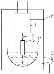
Figure 6 shows a FRANKA plant as constructed simply for
many laboratory tasks.
Figure 2 to Figure 5 show coaxial versions of a FRANKA
plant:
Figure 2 shows how the energy accumulator 1 is separated
from the reactor area 3 by a partition wall in the area of
the high-voltage electrode 5. This is to be incorporated
in particular if spray is generated by the discharge
process.
Figure 3 shows two openings in the encapsulation 6, one in
an area of the covering for charging the reaction vessel 3,
the second being routed out of the reaction vessel 3, for
example, through the bottom. Continuous operation with
charging and removal can be carried on because of these
structural features.
11
CA 02540939 2006-03-31
Figure 4 shows the U-shaped encapsulation 3. This
structural form may be preferred in the case of large
plants for reasons of weight and ease of operation.
Figure 5 shows an inverted structural form, the reaction
vessel 3 being located above the energy accumulator 1.
Such a structural form may be preferable in the case of
gaseous or very light process substances that are easily
agitated.
Figure 6 shows the construction of a conventional FRANKA
plant which, as a fully functioning plant, is additionally
encapsulated by a wall for shielding and as a protection
against contact with live components. The largest
electrical loop is not minimized. In the event of the
pulse, it acts as a powerful transmitting antenna. For
this reason, when used in the industrial context, the
shielding is regulated by legislation.
12
CA 02540939 2006-03-31
List of Components
1. Energy accumulator
2. Output switch/spark gap
3. Reaction vessel
4. End of high-voltage electrode
5. High-voltage electrode with insulator
6. Encapsulation
7. Connection between process vessel and encapsulation
8. Connection between charging apparatus and encapsulation
9. Filler connector
10. Removal connector
13