Note: Descriptions are shown in the official language in which they were submitted.
CA 02541147 2006-03-31
- 1 -
DESCRIPTION
SLIDING SCREEN DOOR
Technical Field
The present invention relates to a screen door attached
to an openirig portion of a building for protection from
insects, which is capable of freely opening and closing by
horizontally pulling a screen being free for expansion and
contraction in a style of an accordion.
Background Art
A sliding screen door is heretofore known as described
in Japanese Unexamined Patent Application Publicatiori No.
2002-371776. In the sliding screen door, a screen
configured to be free for expansion and contraction in a
style of an accordion by means of alternately foldinq in a
reverse direction at numbers of folded portions beincl in
parallel with each other spaced at even intervals is
constructed to be free for opening and closing in a style of
horizontal pulling in a frame body. In the sliding screen
door, in which one end of the aforementioned screen is fixed
to a vertical frame member of the aforementioned frame body
and the other end of the screen is attached to an operating
doorframe for open-and-close operation, which slides along
the aforementioned frame body, a wire whose one end is fixed
CA 02541147 2006-03-31
- 2 -
to the aforementioned vertical frame member is horizontally
inserted into the aforementioned screen and is drooped in
the operating doorframe via a guide member provided in the
aforementioned operating doorframe. In addition, a sinker
is dangled at a tip end of the wire and a spring member is
interposed between the sinker located at a position when the
screen is in a condition of being stretched and a coritacting
portion to be a rising uppermost limit of the sinker.
In the aforementioned known sliding screen door,
stretching force that affects the wire only when the screen
is in a stretched condition is increased without excessively
increasing size of the sinker to be dangled from the wire by
means of installing the aforementioned spring member,
resulting in suppression for expansion of the screen when
the outside force caused by a certain level of stronq wind,
or the like, is affected to the stretched screen. As a
result, both upper and lower ends of screen can be
suppressed from a deviation from a horizontal frame member
as well as possible. However, since the stretching force of
the wire in the stretched condition of the screen cannot be
adjusted, even when the stretching force of the wire in the
stretched condition of the screen due to installing of the
spring member is excessively strong, although the expansion
of the screen due to the wind or the like can further be
suppressed, not only large operating force is required to
CA 02541147 2006-03-31
- 3 -
move the operating doorframe toward a stretched position for
the operation to stretch the screen, but also the operating
doorframe moves at an abnormal speed because strong action
force of the spring member is added to the action force of
the sinker when a locked state of the operating doorframe is
released by a latching mechanism. Further, when the
stretching force of the wire in a case when the screen is in
the stretched condition is excessively weak, although the
operating force for the operating doorframe for stretching
the screen is sufficiently small, there has been a problem
that the expansion of the screen due to the wind or the like
cannot be sufficiently suppressed.
In addition, in the aforementioned sliding screen door,
since length of the horizontal frame member is determined
aligning with an opening of a building where the sliding
screen door is installed, it is required that adjustment of
the length of the wire can be easily performed in a wide
range.
Disclosure of Invention
An object of the present invention is to solve these
and above problems and to provide a sliding screen door
capable of adjusting stretching force of a wire in a wide
range with ease when a screen is in a stretched condition,
and capable of fully suppressing an expansion of the screen
CA 02541147 2006-03-31
- 4 -
due to wind or the like without increasing operating force
for an operating doorframe, for stretching operation of the
screen.
Another object of the present invention is to provide a
sliding screen door capable of easily adjusting the
stretching force of the aforementioned wire by means of only
adjusting an attaching position of an adjusting member by
means of sliding the adjusting member of a wire adjusting
mechanism, and capable of fully increasing and decreasing
the stretching force of the aforementioned wire even when a
moving distance of the adjusting member is short.
Still another object of the present invention is to
provide a sliding screen door capable of covering a screw
for fixing a vertical frame member to an opening portion of
a building, or the wire adjusting mechanism installed in the
vertical frame member by means of utilizing an end plate for
attaching the screen, and along therewith, the screen can be
easily replaced, in addition to that the stretching force of
the wire when the aforementioned screen is in the stretched
condition can be easily adjusted.
A further object of the present invention is to provide
a sliding screen door capable of automatically latching the
operating doorframe with a latching mechanism mounted on the
vertical frame member only when the operating doorframe is
moved to a closing position, and a latching position of the
CA 02541147 2008-12-09
- 5 -
operating doorframe and the latching mechanism can be easily
adjusted.
Still a further object of the present invention is to
provide a sliding screen door configured such that the
latching is not released due to relatively careless
operation, while the structure is simple, because there is
no guarantee that a dangerous situation does not occur in
case the screen is unexpectedly folded when the latching of
the operating doorframe with the vertical frame member is
unexpectedly released by means of the aforementioned
latching mechanism in the sliding screen door configured to
house the screen by means of action force of the
aforementioned sinker and a spring member.
To solve the above-described problems, the invention
provides a sliding screen door comprising: a frame body; an
operating doorframe mounted to the frame body for movement
in a horizontal direction; a pleated screen having vertical
pleats, wherein one end of the screen is fixed to a vertical
frame member of the frame body via an elongated endplate and
another end of the screen is attached to the operating
doorframe, whereby the screen is freely movable in the frame
body to be fully opened by movement of the operating
doorframe away from the vertical frame member; a wire having
one end fixed to the vertical frame member via a wire
CA 02541147 2008-12-09
- 6 -
adjusting mechanism and being horizontally inserted into the
screen, wherein the wire extends into the operating
doorframe and is guided downward therein via a guide member
provided in the operating doorframe; a sinker mounted to an
end of the wire in the operating doorframe and freely
vertically movable in the operating doorframe, whereby the
weight of the sinker stretches the wire; and a spring member
in the operating doorframe and surrounding the wire, the
spring member being positioned between the sinker and a
contacting portion of the operating doorframe, wherein the
wire adjusting mechanism is adjustably mounted to the
vertical frame member, and wherein the mounting position of
the wire adjusting mechanism on the vertical frame member is
adjusted such that the spring member is compressed between
the sinker and the contacting portion when the screen is
fully opened, whereby a resilient expansion force of the
spring applies a stretching force to the wire, wherein the
wire adjusting mechanism comprises a guide part attached to
the vertical frame member, and an adjusting member capable
of sliding along a longitudinal direction of the vertical
frame member and being attached to the vertical frame
member, wherein the wire is passed through the guide part
and fixed to one of the guide part and the adjusting member,
wherein the vertical frame member comprises a longitudinal
CA 02541147 2008-12-09
- 7 -
sliding groove slidably housing the guide part and the
adjusting member, and opening in a direction facing the
screen, and wherein the elongated endplate of the screen is
detachably mounted to the vertical frame member so as to
cover the guide part and the adjusting member in the sliding
groove.
Preferably, the sliding screen door as described above,
wherein the adjusting member is an approximately plate-
shaped member comprising a first wire connecting portion and
a first screw hole, wherein the adjusting member is
detachably fixed to the sliding groove via a first fixing
screw in the first screw hole, wherein the first fixing
screw is screwed from an opening side of the sliding groove
to the first screw hole, and wherein the guide part is an
approximately plate-shaped member fixed to the sliding
groove, comprising a guide hole penetrating the guide part
for the wire to be passed through, and a second wire
connecting portion.
Preferably, the sliding screen door as described above,
wherein the sliding groove in the vertical frame member has
an approximately C-shaped section, comprising projecting
walls inwardly protruding at a pair of groove side walls of
the sliding groove, and wherein the adjusting member is
detachably fixed to the sliding groove by sandwiching the
CA 02541147 2008-12-09
- 8 -
projecting walls between the adjusting member and a first
nut where the first fixing screw is screwed through the
first screw hole of the adjusting member.
Preferably, the sliding screen door as described above,
wherein the guide part comprises a second screw hole where a
second fixing screw for detachably fixing the guide part to
the sliding groove is screwed, and wherein the second fixing
screw is screwed from an opening side of the sliding groove
to the second screw hole.
Preferably, the sliding screen door as described above,
wherein the sliding groove in the vertical frame member has
an approximately C-shaped section, comprising projecting
walls inwardly protruding at a pair of groove side walls of
the sliding groove, and wherein the guide part is detachably
fixed to the sliding groove by sandwiching the projecting
walls between the guide part and a second nut where the
second fixing screw is screwed through the second screw hole
of the guide part.
In a sliding screen door having the above-described
construction, since a wire adjusting mechanism for adjusting
force of repulsion of the aforementioned spring member that
occurs when the aforementioned screen is in a stretched
condition, by means of adjusting length of the
aforementioned wire is installed in the aforementioned
CA 02541147 2008-12-09
- 9 -
vertical frame member, the stretching force of the wire
caused when the screen is in the stretched condition can be
easily adjusted. Accordingly, the sliding screen door
capable of appropriately suppressing expansion of the screen
caused by wind or the like can be provided without
increasing operating force for an operating doorframe for
stretching operation of the screen. In addition, since the
CA 02541147 2006-03-31
- 10 -
aforementioned spring member is brought to a slightly
compressed state in the stretched condition of the screen,
the wire adjusting mechanism can increase or decrease the
force of repulsion of the aforementioned spring member only
by means of slightly shortening or lengthening the length of
the aforementioned wire. Accordingly, the stretching force
of the wire when the screen is in the stretched condition
can be easily adjusted.
Further, in the aforementioned sliding screen door, the
aforementioned wire adjusting mechanism is provided with a
guide part attached to the vertical frame member and the
adjusting member attached to the vertical frame member in a
manner so as to be slidable along a longitudinal direction
thereof, and so as to be detachable from the vertical. frame
member at the slid position thereof. Since the length of
the wire which is united and fixed to the guide part and the
adjusting member is adjusted only by means of sliding the
aforementioned adjusting member and by means of adjusting a
position where the adjusting member is attached to the
vertical frame member, the length of the wire can be easily
adjusted. Furthermore, since the length of the
aforementioned wire can be adjusted by a moving distance of
the adjusting member or by twice as much as the moving
distance of the adjusting member, even the moving distance
of the adjusting member is short, the stretching force of
CA 02541147 2006-03-31
- 11 -
the aforementioned wire can be fully increased or decreased.
In addition, since a latching mechanism for
automatically latching with a receiving hole formed in the
operating doorframe and for locking the operating doorframe
at a closing position, when the operating doorframe -s moved
to the stretch position is installed in the aforementioned
vertical frame member, the latching mechanism is
automatically latched only by moving the operating doorframe
toward the closing position and the operating doorframe can
be locked at the closing position. Further, the
aforementioned latching mechanism is provided with a
position adjusting device for adjusting a lowering position
where a latch main body is lowered by its own weight.
Therefore, a latching position of the operating doorframe
with the latching mechanism can be easily adjusted.
Furthermore, in the sliding screen door configured to
be able to house the screen by means of action force of the
aforementioned sinker and the spring member, when the
latching of the operating doorframe with the vertical frame
member by means of the latching mechanism is carelessly
released, there is no guarantee that a dangerous situation
does not occur in case the screen is unexpectedly folded.
In general, an operation member for releasing the latching
is relatively easy to operate when the operation member is
configured to be able to release the latching by means of
CA 02541147 2006-03-31
- 12 -
pressing down the same from above. However, in this case,
on the contrary, the possibility that the latching is
carelessly released is large. However, in the
aforementioned latching mechanism, since the latching is
configured be released by means of raising the operating
member from below at only a certain distance, the latching
is not released by relatively careless operation, such as
that a hand moved by the side of the operating member
touches the same or something taken by hand touches the
operating member. In addition, because the latching is
released by means of raising the operating member, a hook
portion of the latching mechanism can be hooked by force of
gravity and there is no need to hook the operating member by
a spring or the like, resulting in simplifying the structure.
Brief Description of the Drawings
FIG. 1 is a partially broken elevation showing an
embodiment of a sliding screen door with respect to the
present invention;
FIG. 2 is a cross-sectional plan view of the same;
FIG. 3 is a side elevation showing an operating
doorframe in the embodiment;
FIG. 4 is an enlarged elevation of a main part in the
embodiment;
FIG. 5 is a partially enlarged cross-sectional plan
CA 02541147 2006-03-31
- 13 -
view of the embodiment;
FIG. 6 is a partially broken elevation showing a.
condition in which a latching mechanism is installed in a
side frame member of the embodiment;
FIG. 7 is a perspective view showing a condition in
which the latching mechanism installed in the side frame
member is latched with the operating doorframe of the
embodiment;
FIG. 8 is a perspective view of a main part of the
operating doorframe;
FIG. 9 is perspective view showing an adjusting
condition of a position of the latching mechanism installed
in the side frame member;
FIG. 10 is perspective view showing a condition in
which length of a wire is adjusted by means of a wire
adjusting mechanism;
FIG. 11 is a perspective view showing a condition in
which a side frame side end plate of the screen is being
housed in a concave groove of the side frame member i_n which
the wire adjusting machine is installed;
FIG. 12 is a perspective view showing a condition in
which the side frame side end plate of the screen is housed
in the concave groove of the side frame member;
FIG. 13 is a perspective view showing a condition in
which the side frame side end plate of the screen housed in
CA 02541147 2008-12-09
- 14 -
the concave groove of the side frame member is fixed to the
concave groove by means of a fixing member;
FIG. 14 is a partially enlarged cross-sectional plan
view showing a condition in which the side frame side end
plate of the screen is being housed in the concave groove of
the side frame member;
FIG. 15 is a partially enlarged cross-sectional plan
view showing a condition in which the side frame side end
plate of the screen housed in the concave groove of the side
frame member is fixed to the concave groove by means of the
fixing member;
FIG. 16 is a plan view showing a condition of wire-
uniting of a wire adjusting mechanism installed in the side
frame member; and
FIG. 17 is a plan view showing a condition of another
wire-uniting.
Best Mode for Carrying Out the Invention
FIGs. 1 through 17 illustrate the embodiment of a
sliding screen door with respect to the present invention.
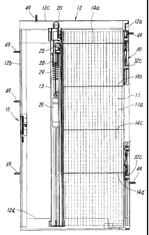
The sliding screen door is constructed such that a
screen 11 for protection from insects is configured to be
free for opening and closing in the style of horizontal
pulling in a frame member 12 fixed to an opening portion of
a building. Further, the screen 11 for protection from the
CA 02541147 2006-03-31
- 15 -
insects is configured to be free for expansion and
contraction in the style of an accordion by means of
alternately folding in reverse directions at the numbers of
folded portions lla which is in parallel with each other and
is spaced at even intervals, as shown in FIGs. 1 and 2. The
frame body 12 is constructed by mutually connecting each of
a pair of vertical frame members, 12a and 12b made of
aluminum or synthetic resin and upper and lower horizontal
frame members, 12c and 12d, at four corners.
One end of the aforementioned screen 11 is fixed. to one
of the vertical frame members 12a of the aforementioned
frame body 12 and the other end of the screen 11 is attached
to an operating doorframe 13 for opening and closing
operation, which slides along the upper and lower horizontal
frame members, 12c and 12d, of the aforementioned frame body
12. The operating doorframe 13 causes a track roller 20
attached to an upper end thereof to run on a rail provided
in an upper part of the horizontal frame member 12c. In
addition, upper and lower ends of the screen 11 are quided
by means of a groove provided in the aforementioned
horizontal frame members, 12c and 12d.
In the aforementioned sliding screen door, wires, 14a
through 14d are inserted into upper and lower portions in
the screen 11 and in the middle portions thereof at
multistage in each of horizontal directions spaced at
CA 02541147 2006-03-31
- 16 -
approximately even intervals. Further, each of one ends of
the wires, 14a through 14d, is attached to the
aforementioned vertical frame member 12a and the other ends
of these wires 14a through 14d are inserted through the
operating doorframe 13 after inserting through the screen 12.
In the wires, 14a, 14b, 14c, and 14d, the wires other than
the topmost wire 14a are guided upward in the operating
doorframe 13 via a turnaround element (not shown), and are
drooped in the operating doorframe 13 together with the
topmost wire 14a via a guide member (roller) 25 provided at
an upper part of the operating doorframe 13. Further, a
sinker 26 is dangled at a tip end of those wires, 14a
through 14d, in the operating doorframe 13.
Although the aforementioned wires, 14a through 14d,
being drooped in the operating doorframe 13 can be
individually drooped and the sinker 26 can be attached to
the tip end thereof, the wires may be drooped by the lump.
Thus, when a plurality of the wires, 14a through 14d, are
inserted into the screen 11 at multistage, and the sinker 26
is dangled at the wires in the operating doorframe 13, the
operating doorframe 13 can be moved in parallel by means of
the stretching force being uniformly affecting each of the
wires. Further, expansion or the like of the screen 11
toward the lee side by an action of a wind pressure or the
like can be suppressed.
CA 02541147 2006-03-31
- 17 -
Furthermore, the aforementioned sliding screen door is
provided with a spring member 29 in a manner so as to be
interposed between the aforementioned sinker 26 and the
contacting portion 28 to be a rising uppermost limit of the
sinker. The spring member 29 being interposed between the
aforementioned sinker 26 and the contacting portion 28 is
provided in a manner so as to be in a slightly compressed
condition when the screen 11 is in a stretched condition.
As for the aforementioned spring member 29, although it is
desirable to use a coil spring fitting around a periphery of
the wire, a sponge-like member or other elastic member can
be used.
In the aforementioned sliding screen door, a wire
adjusting mechanism 30 is installed in the aforementioned
vertical frame member 12a, as shown in FIGs. 10 and 1.1, and
FIGs. 16 and 17. In the wire adjusting mechanism 30, force
of repulsion of the aforementioned spring member 29 when the
aforementioned screen 11 is in the stretched condition is
adjusted by means of adjusting length of the wire 14 and
thereby the stretching force of the aforementioned wires,
14a through 14d (Hereinbelow, one of, or a plurality of
wires in the wires, 14a through 14d is referred to as "wire
14" for short.) when the aforementioned screen 11 is in the
stretched condition is adjusted.
In a detailed description, the aforementioned vertical
CA 02541147 2006-03-31
- 18 -
frame member 12a is composed of a pair of side walls 41
extending in a longitudinal direction, a connecting wall 42
connecting the pair of the side walls 41 and having a slide
groove 44 extending in a longitudinal direction, and a pair
of projecting walls 41a projecting toward inside from one
end side of the aforementioned pair of the side walls 41
while extending in a longitudinal direction, and forming a
concave groove 45 at an inside thereof in a longitudinal
direction, as shown in FIGs. 14 and 15. The aforementioned
slide groove 44 is a groove having approximately concave-
shaped cross-section, provided with a pair of groove side
walls 44b being in parallel with the pair of the side walls
41 of the aforementioned vertical frame member 12a, and a
groove bottom wall 44a connecting the pair of the groove
side walls 44b, and the pair of the groove side walls 44b
has a projecting wall 44c that projects inwardly.
The aforementioned wire adjusting mechanism 30 is
provided with a guide part 31 configured to be slidable in
the aforementioned slide groove 44 and to be able to be
fixed to the aforementioned slide groove 44 at the slid
position thereof and an adjusting member 32.
The aforementioned guide part 31 is a member having
approximately plate-shape composed of a guide hole 31a
formed by means of penetrating the guide part 31, through
which the aforementioned wire 14 passes, a wire connecting
CA 02541147 2006-03-31
- 19 -
portion 31b that is bent and protruded by means of cutting
open and turning over the material in a direction opposite
to the adjusting member 32 side so as to guide, and unite
and fix the aforementioned wire 14, and a screw hole (not
shown) into which a fixing screw 34 for detachably fixing
the guide part 31 to the aforementioned slide groove 44 is
inserted. On the other hand, the aforementioned adjusting
member 32 is a member having approximately plate-shape
composed of a wire connecting portion 32a that is berit and
protruded by means of cutting open and turning over the
material in a direction opposite to the guide part 31 side
so as to guide, and unite and fix the aforementioned wire 14,
and a screw hole (not shown) into which the fixing screw 35
for detachably fixing the adjusting member 32 to the
aforementioned slide groove 44 is inserted.
The fixing screws, 34 and 35, of the aforementioned
guide part 31 and the adjusting member 32 are screwed into
nuts, 31c and 32c, housed in the groove bottom wall 44a side
of the aforementioned projecting wall 44c of the
aforementior_ed slide groove 44 (Refer to FIGs. 1 and 14.),
and are fixed by sandwiching the projecting wall 44c at both
sides of the slide groove 44 between the aforementioned
guide part 31 and the nut 31a, and the adjusting member 32
and the nut 32a. However, other device may be employed as
follows, for example. The screw holes in the guide part 31
CA 02541147 2006-03-31
- 20 -
and the adjusting member 32, to which the fixing screws, 34
and 35, are inserted are formed to have female screws, and
the guide part 31 and the adjusting member 32 are housed in
the groove bottom wall 44a side of the projecting wall 44c.
Then, the aforementioned guide part 31 and the adjusting
member 32 are pressed to the aforementioned projectirig wall
44c due to reaction force caused by the fixing screws, 34
and 35, which are screwed into the aforementioned screw
holes and pressed to the groove bottom wall 44a of the
aforementioned slide groove 44. Thus, the guide part 31 and
the adjusting member 32 can also be detachably fixed to the
aforementioned slide groove 44 at an arbitrary slid position.
Further, at a head portion of the fixing screw 34 by which
the aforementioned guide part 31 is fixed, a sealing piece
31d for covering is adhered to prevent the fixing screw 34
from being removed by a user or the like.
The aforementioned wire adjusting mechanism 30 is
configured such that, as shown in FIG. 16, the wire 14 which
is folded back through the guide hole 31a of the
aforementioned guide part 31 is united and fixed to the wire
connecting portion 32a of the aforementioned adjustirig
member 32, or, as shown in FIG. 17, the wire which is folded
back through the guide hole 31a of the aforementioneci guide
part 31 is further folded back at the wire connectinq
portion 32a of the aforementioned adjusting member 32, and
CA 02541147 2006-03-31
- 21 -
is returned again to the aforementioned guide part 31, and
further, is united and fixed to the wire connecting portion
31b of the guide part 31.
The aforementioned wire adjusting mechanism 30 is
configured such that the aforementioned adjusting member 32
is slid in a condition that the aforementioned wire 14 is
united and fixed to the aforementioned adjusting member 32
or the aforementioned guide part 31, and the attaching
position of the adjusting member 32 is adjusted. Thereby,
the length of the aforementioned wire 14 can be adjusted.
Accordingly, the length of the aforementioned wire 14,
namely the stretching force of the wire 14 when the screen
11 is in the stretched condition can be easily adjusted by
means of only adjusting the attaching position of the
aforementioned adjusting member 22 by sliding the same.
In a uniting condition of the wire, shown in FIG. 16,
although the length of the aforementioned wire 14 cari be
adjusted to the extent of the distance at which the
aforementioned adjusting member 32 moves, in a unitirg
condition, shown in FIG. 17, since the wire 14 being folded
back passing through the guide hole 31a of the
aforementioned guide part 31 is further folded back at the
wire connecting portion 32a of the aforementioned adjusting
member 32 and united and fixed to the wire connecting
portion 31b of the aforementioned guide part 31. As a
CA 02541147 2006-03-31
- 22 -
result, the length of the wire 14 can be adjusted by the
length twice as much as the distance for which the
aforementioned adjusting member 32 moves. Accordingly, in a
case when the moving distance of the adjusting member 32 is
short, the length of the wire can be adjusted in a wide
range.
Further, the aforementioned wire adjusting mechanism 30
is configured such that since the spring member 29
interposed between the sinker dangled at the tip end of the
wire 14 and the contacting portion 28 to be a rising
uppermost limit of the sinker is compressed via the wire 14,
the force of repulsion of the aforementioned spring member
29, namely the stretching force of the wire can be easily
adjusted by means of only adjusting the length of the
aforementioned wire 14 by varying the attaching position of
the aforementioned adjusting member 32 by sliding the same.
As a result, there is no possibility that the operating
force for the operating doorframe required for stretching
operation for the screen becomes excessively large or the
like, and the expansion of the screen caused by he wind or
the like can be appropriately suppressed.
Furthermore, the aforementioned sliding screen door is
configured such that, as shown in FIGs. 11 through 15, the
aforementioned screen 11 is provided with a long plate-
shaped side frame side end plate llb, and the side frame
CA 02541147 2006-03-31
- 23 -
side end plate l1b is housed between a pair of concave
grooves 45 facing each other and extending in a longitudinal
direction, which are provided in the aforementioned vertical
frame member 12a, while passing through a space between a
pair of projecting walls 41a of the aforementioned vertical
frame member 12a. The side frame side end plate llb is
detachably fixed to the concave groove 45 by means of being
sandwiched between the connecting wall 42 that constitutes
one side of the side wall of the concave groove and a
plurality of fixing members 48 being detachably fixed to the
pair of the concave grooves 45.
The aforementioned fixing member 48 is provided with a
main body portion 48a having approximately rectangular shape,
provided with a pair of hooking ridges 48b and a pair of
elastic leg portions 48c extending from both sides of the
main body portion 48a. The aforementioned fixing member 48
is detachably fixed to the concave groove 45 by means of
elastic force of the elastic leg portion 48c by inserting
the aforementioned elastic leg portion 48c into one side of
the concave groove 45, and inserting the main body portion
48a into the other side of the concave groove 45 whil.e
compressing the elastic leg portion 48c.
In the aforementioned sliding screen door, since the
aforementioned screen 11 is provided with the long plate-
shaped side frame side end plate llb, and the side frame
CA 02541147 2006-03-31
- 24 -
side end plate llb can be detachably attached to the
aforementioned vertical frame member 12a, a screw 49 for
fixing the aforementioned vertical frame member 12a to the
opening portion of the building (Refer to FIGs. 1 or 11.),
or the aforementioned wire adjusting mechanism 30 installed
in the aforementioned vertical frame member 12a can be
covered and the side frame side end plate llb can be easily
detached by means of the aforementioned fixing member 48.
Accordingly, the screen 11 can be easily replaced.
Further, in the aforementioned sliding screen door, as
shown in FIGs. 1, 2, 6, 7, and 9, a latching mechanism 15 is
provided in the vertical frame member 12b, at which the
screen 11 is not fixed. The latching mechanism 15 is
configured such that when the operating doorframe 13 moves
to a closing position where the operating doorframe 1.3
collides with the vertical frame member 12b, the latching
mechanism 15 is automatically latched with a receiving hole
13a formed in the operating doorframe 13 (Refer to FIGs. 3,
7, and 8.), and locks the operating doorframe 13 at the
closing position.
Accordingly, the operating doorframe 13 is held at the
closing position, where the screen 11 is brought to be in a
stretched condition, by means of the aforementioned latching
mechanism 15 resisting against the stretching force of the
wires 14a through 14d caused by the sinker 26.
CA 02541147 2006-03-31
- 25 -
The aforementioned vertical frame member 12b is
provided with a pair of side walls 51 extending in a
longitudinal direction and a connecting wall 52 having a
sliding groove 53 that connects the pair of the side walls
51 and extending along a longitudinal direction, as shown in
FIG. 9. The vertical frame member 12b further includes a
notched portion 51a in the side wall 51 along a longitudinal
direction at. a position where the aforementioned latching
mechanism 15 is installed. In addition, a pair of
projecting walls 54 forming the aforementioned sliding
groove 53 is inwardly projected from the pair of the side
walls 51.
The aforementioned latching mechanism 15 is configured
such that, as shown in FIGs. 6 through 9, a pair of
operating members 17b protruding outside from a notched
portion 51a of the aforementioned pair of the side walls 51
is consecutively installed to a sliding piece 16 inserted
into the aforementioned sliding groove 53 in a manner such
that both side ends are engaged with insides of the
projecting walls 54 and a base plate portion 17a being
connected with the sliding piece 16 so as to cover an outer
face thereof. Accordingly, the latching mechanism 15 is
provided with a latch main body 17 which is slidable in an
above and below direction with the aforementioned sliding
piece 16 within a definite range and the latching mechanism
CA 02541147 2006-03-31
- 26 -
15 is further provided with a position adjusting dev=~ce 55
for adjusting a lowering position of the sliding piece 16
and the latch main body 1"7.
In more detailed explanation, the aforementioned
sliding piece 16 includes a hooking portion 16a to be hooked
with the receiving hole 13a formed in the aforementioned
operating doorframe 13, and in the hooking portion 16a, a
slanting portion 16b with which a lower edge of the
receiving hole 13a of the aforementioned operating doorframe
13 collides when the aforementioned operating doorframe 13
moves to the closing position. The sliding piece 16 further
includes a hooking hole 16c for hooking a hooking portion
17e provided at both ends of the latch main body 17 i_n a
longitudinal direction.
On the other hand, the aforementioned latch main body
17 is provided with the pair of the operating members 17b
respectively protruding outward from the notched portion 51a
of the pair of the side walls 51 in the aforementioned base
plate portion 17a, a penetrating hole 17c there the
aforementioned hooking portion 16a passes through, an
elongated hole 17d formed at a lower position, and the
aforementioned hooking portion 17e to be hooked with the
hooking hole 16c of the slide piece 16.
Further, the aforementioned position adjusting device
55 is provided with a stopper member 56 having a screw hole
CA 02541147 2006-03-31
- 27 -
at a center thereof and being inserted in a manner so as to
be hooked with inside of the projecting walls 54 in the
aforementioned sliding groove 53, and an adjusting screw 57
to be screwed into a screw hole of the aforementioned
stopper member 56 through the elongated hole 17d formed in
the aforementioned latch main body 17. The stopper member
56 is fixed in a manner so as to be free for adjusting a
position by being pressed to the projecting walls 54 of the
sliding groove 53 by means of reaction force that occurs
when the aforementioned adjusting screw 57 which is screwed
into the screw hole presses the bottom wall of the sliding
groove 53 by screwing operation. The aforementioned stopper
member 56 is configured to limit the lowering position of
the sliding piece 16 and the latch main body 17 that lower
by their own weight, and a hooking portion to be hooked with
them at the set lowering position of the sliding piece 16 or
the latch main body 17 is formed at an upper end portion
thereof.
In the aforementioned latching mechanism 15, since the
aforementioned stopper member 56 is fixed to the
aforementioned projecting walls 54 in a manner so as to be
position adjustable, the lowering position of the
aforementioned latch main body 17 being lowered by its own
weight can by easily adjusted. Accordingly, the
aforementioned latching mechanism 15 can be easily
CA 02541147 2006-03-31
- 28 -
configured such that the hooking portion 16a is positioned
to be able to be hooked with the receiving hole 13a of the
aforementioned operating doorframe 13 when the
aforementioned latch main body 17 is placed at a lowering
position.
In the latching mechanism 15, when the aforementioned
operating doorframe 13 moves toward the closing position, a
peripheral wall of the receiving hole 13a of the
aforementioned operating doorframe 13 passes through, while
pressing up the slanting portion 16b of the aforementioned
hooking portion 16a, and when the peripheral wall of the
receiving hole 13a of the aforementioned operating doorframe
13 passes over the slanting portion 16b of the
aforementioned hooking portion 16a, the aforementioned latch
main body 17 falls down by its own weight and the
aforementioned hooking portion 16a is automatically latched
with the peripheral wall of the receiving hole 13a of the
aforementioned operating doorframe 13. Therefore, the
aforementioned hooking portion 16a can be automatically
latched with the receiving hole 13a of the aforementioned
operating doorframe 13 only by moving the aforementicned
operatirig doorframe 13 toward the closing position, and
accordingly, the aforementioned operating doorframe 13 can
be locked at the closing position.
When the locked state of the aforementioned latching
CA 02541147 2006-03-31
- 29 -
mechanism 15 is released, it is sufficient to only press up
the aforementioned operating member 17b resisting against
the force of gravity. When the aforementioned operating
member 17b is pressed up, the aforementioned hooking portion
16a is raised and the latched state of the hooking portion
16a with the receiving hole 13a of the aforementioned
operating doorframe 13 is released. As a result, the
aforementioned operating doorframe 13 moves toward ari
opening direction by means of action force of the
aforementioned sinker 26 that affects the aforementioned
operating doorframe 13 via the wire 14.
Thus, the embodiment of the sliding screen door with
respect to the present invention is described in detail.
However, the present invention is not limited to the sliding
screen door described in the aforementioned embodiment, and
various modifications can be made in design without
departing from the spirit of the invention described in the
claims of the present invention.