Note: Descriptions are shown in the official language in which they were submitted.
CA 02541167 2006-03-31
WO 2005/038109 PCT/US2004/030814
930075-2001
COMPACT JACQUARD SELECTING CARD USING
PIEZOELECTRIC ELEMENTS
BACKGROUND OF THE INVENTION
Field of the Invention
The present invention relates to selecting cards for Jacquard-type
equipment. More specifically, the present invention relates to a piezoelectric
actuated selecting card for use in a Jacquard loom.
Description of the Prior Art
The use of Jacquard selection devices in weaving looms to produce
intricate patterns by controlling the lifting of selected warp yarns is well
known
in the art. The separation formed between the lifted warp yarns and the non-
lifted warp yarns is referred to as the shed. The Jacquard mechanism allows
for
independent movement of each warp yarn by controlling hooks (latches,
catches) which engage matching hooks on rods (healds) connected to each warp
yarn in a harness. A lifting device (or board) is used to raise or lower those
warps in the harness whose corresponding hooks have been engaged. By
coordinating the movement of the hooks, sequences of warp yarns can be
selected and lifted while filling yarns are passed through the shed. In this
manner, the Jacquard selection device is used to create the woven pattern.
Jacquard selection devices can be used in looms in either a closed shed
or an open shed arrangement. In the closed shed arrangement, a single lifting
device having an engaging hook for each warp in the harness is used. Whereas,
the open shed configuration uses a double hook system of two lifting devices
which provide pairs of engaging hooks which connect with pairs of (ascending
and descending) rods that lift a single warp. The open shed conftguration has
two lifting devices and requires only a single move of each lifting device to
create the shed, while the closed shed configuration has one lifting device
but
requires two moves.
Historically, the Jacquard mechanism involved a paper selection card
having a pattern of punched holes. The selection card would allow those rods
1 ~ 00144316
~.......,."., T i!.,;1 TvTy.
CA 02541167 2006-03-31
WO 2005/038109 PCT/US2004/030814
(or hooks) located at a hole to pass through and lift the corresponding warps,
whereas the rods would be blocked at the locations without holes. By changing
or shifting the selection card after each pass, the weave pattern could be
formed.
This process was mechanically complex and often led to breakdowns
and fabric quality problems. The mechanical complexity has been a major
obstacle to increasing the efficiency of Jacquard machines. In response,
several
electrically selected loom latches have been proposed. For example, U.S.
Patent No. 6,073,662 to Herbepin, which is incorporated herein by reference,
teaches the use of an electromagnetic device having a coil to control the
position of each catch relative to a corresponding hook in a Jacquard
selection
device. When an electromagnet device is powered, the attached catch is
positioned to engage the corresponding hook. The shed is opened by operation
of a lifting board. Despite such proposed solutions, electrical and
electromagnetic selection devices remain relatively large in comparison to the
scale of the weave pattern.'"
A refinement of this electrical approach has been the application of
piezoelectric elements to Jacquard selection devices. Piezoelectric actuator
elements are devices that produce a lateral or longitudinal displacement with
a
high force capability when an operating voltage is applied. There are many
applications where a piezoelectric actuator may be used, such as ultra-precise
positioning and the generation/handling of high forces or pressures in static
or
dynamic situations.
Actuator configuration can vary greatly depending on application. For
example, a flexure strip of piezoelectric material can be used to produce a
transverse displacement. Piezoelectrics can also be stacked together to
increase
the displacement.
These devices are especially useful for controlling vibration, positioning
applications and quick switching. For example, piezoelectric actuators can be
designed to produce strokes of several micrometers at ultrasonic (>20kHz)
frequencies.
The critical specifications for piezoelectric actuators are the
displacement, force and operating voltage of the actuator. Other factors to
2 00144316
CA 02541167 2006-03-31
WO 2005/038109 PCT/US2004/030814
consider are stiffness, resonant frequency and capacitance. Stiffness is a
term
used to describe the force needed to achieve a certain deformation of a
structure.
For piezoelectric actuators, it is the force needed to elongate the device by
a
certain amount.
Numerous approaches have been proposed to improve the operation of
Jacquard-type weaving machines by incorporating piezoelectric elements. For
example, U.S. Patent No. 5,392,818 to Seiler discloses a needle selector for a
Jacquard weaving machine similar to prior art mechanical devices only using
piezoelectric transducers to adjust each blocking element. U.S. Patent No.
6,470,919 to Wardle discloses an individual warp selector wherein a
piezoelectric element drives a motor which mechanically moves a rigid heald.
U.S. Patent No. 5,464,046 to McIntyre discloses another individual warp
selector wherein a piezoelectric element mechanically slides a warp selector
in
the longitudinal direction. U.S. Patent No. 5,647,403 to Willbanks discloses
using a piezoelectric element as a mechanical brake on the movement of a
Jacquard warp selector. U.I~. Patent No. GB 2 276 637 to Seiler and U.S.
Patent No. 5,666,999 to Dewispelaere disclose using piezoelectric elements as
controls (locks) on the movement of catches for engaging lifting hooks in an
open shed loom arrangement. However, each of these approaches simply uses
the piezoelectric element to activate the mechanical elements which select the
warp yarns. Because these approaches retain many of the complex mechanical
features of the prior art, they exhibit many of the same limitations. For
example, the size of these devices is not amenable to weaving high density
patterns.
Therefore, a need exists for a Jacquard selection device which is
mechanically reliable, operates at high-speed, has low power consumption, and
is small enough to provide for high density warp selection.
The present invention provides a solution to the problem of providing a
high density Jacquard selection device which is high-speed, reliable, and low
power.
3 00144316
CA 02541167 2006-03-31
WO 2005/038109 PCT/US2004/030814
SUMMARY OF THE INVENTION
Accordingly, the present invention is an electronic selection card for a
Jacquard machine which is high density, compact, and reliable.
The present invention is a selection device for a Jacquard machine. The
device has a parallel array of evenly spaced piezoelectric actuated flexure
elements which lie in a plane. Each flexure element in the array has a
corresponding hook element connected to one end. A holding bar connects a
second end of each flexure element in the array and lies in the plane. An
axial
rod parallel to the holding bar passes through an axis hole in each hook
element,
thereby providing a common axis for each hook element to pivot. Each hook
element is independently positioned by actuating the piezoelectric in the
corresponding flexure element, thereby causing the flexure element to bend out
of the plane and forcing the connected hook element to pivot about the common
axis.
Other aspects of the present invention include that the selection device
may be an electronic selection card for a Jacquard loom used to weave fabric
patterns. The hook elements may be used to select warp yarns from a harness
for lifting to form a shed during weaving.
In a preferred embodiment, the array comprises twenty-four (24)
piezoelectric actuated flexure elements and corresponding hook elements
spaced within a length of less than 90 rnm.
In another embodiment, each hook element comprises two opposing
hooks.
The present invention will now be described in more complete detail
with frequent reference being made to the drawing figures, which are
identified
below.
BRIEF DESCRIPTION OF THE DRAWINGS
For a more complete understanding of the invention, reference is made
to the following description and accompanying drawings, in which:
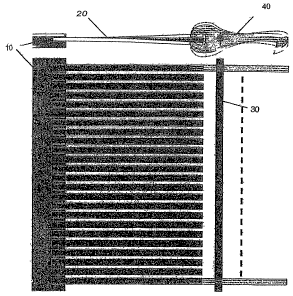
Figure 1 is a front and side view of an exemplary compact selection card
in accordance with the teachings of the present invention;
00144316
CA 02541167 2006-03-31
WO 2005/038109 PCT/US2004/030814
Figure 2 is a side view of an exemplary double hook compact selection
card in accordance with the teachings of the present invention; and
Figure 3 shows comparison views of the closed shed operating cycle for
a prior art electric selection device and a piezoelectric selection device in
accordance with the teachings of the present invention.
DETAILED DESCRIPTION OF THE PREFERRED EMBODIMENTS
The present invention is a compact selecting card for use in a Jacquard
device; e.g. a loom. The selecting card comprises an array of selecting hooks
which are individually positioned by piezoelectric actuators. Such a card
provides many advantages over prior art electronic selection cards. For
example, the present card exhibits improved operating speed and positional
control, lower power consumption, and increased lifetime.
Figure 1 is a front and side view of an exemplary compact selection card
in accordance with the teachings of the present invention. The selection card
has a parallel array of evenly spaced piezoelectric actuated flexure elements
20
which lie in a plane. Each flexure element in the array has a corresponding
hook element 40 connected to one end. A holding bar 10 connects the other end
of each flexure element 20 in the array and lies in the plane. An axial rod 30
parallel to the holding bar passes through an axis hole in each hook element
40,
thereby providing a common axis for each hook element to pivot. The holding
bar 10 and axial rod 30 combine to create a no-play assembly for the flexure
elements 20. This allows the piezoelectric elements to supply all their force
and
control to the attached hooks 40. Each hook element 40 is independently
positioned by actuating the piezoelectric in the corresponding flexure element
20, thereby causing the flexure element to bend out of the plane and forcing
the
connected hook element to pivot about the common axis.
The present selection device is suitable for use in a Jacquard loom used
to weave fabric patterns. The hook elements may be used to select warp yarns
from a harness for lifting to form a shed during weaving. This arrangement of
flexure elements allows for a selection hook density such that each harness in
a
loom can be driven independent from one another.
00144316
CA 02541167 2006-03-31
WO 2005/038109 PCT/US2004/030814
In a preferred embodiment, the array comprises twenty-four (24)
piezoelectric actuated flexure elements and corresponding hook elements
spaced within a length of less than 90 mm. These hooks correspond to the yarns
in a 24 warp yarn harness. This hook density is sufficient for each harness on
a
loom to be driven independently. For control of fewer than 24 yarns, the
harness is simply not threaded for those yarns. Conversely, to control more
than 24 yarns, multiple selection cards and harnesses can be used.
Figure 2 is a side view of another embodiment of the invention in which
each hook element comprises two opposing hooks. As in the single hook
embodiment, this double hook selection card has a parallel array of evenly
spaced piezoelectric actuated flexure elements 20 which lie in a plane. A
holding bar 10 connects one end of each flexure element 20 in the array and
lies
in the plane. Attached to the other end of each flexure element are a pair of
hook elements 40. Axial rods 30 parallel to the holding bar pass through an
axis
hole in each hook of the double hook elements 40, thereby providing common
axes for the hook elements to pivot. The holding bar 10 and axial rods 30
combine to create a no-play assembly for the flexure elements 20. This allows
the piezoelectric elements to supply all their force and control to the
attached
hooks 40. Each pair of hooks are independently positioned by actuating the
piezoelectric in the corresponding flexure element 20, thereby causing the
flexure element to bend out of the plane and forcing the connected hook
elements to pivot about the common axis. Because of the double hook
configuration, a preloaded mechanism 50 such as a spring is needed to bias the
hooks back into their neutral in plane position.
Both the single hook and double hook embodiments of the present
selection card can be used in conjunction with various lifting devices in both
closed shed and open shed configurations.
Figure 3 shows comparison views of the operating cycle of a closed shed
configuration for: 3A) a prior art electric selection device and 3B) a
piezoelectric selection device in accordance with the teachings of the present
invention.
00144316
CA 02541167 2006-03-31
WO 2005/038109 PCT/US2004/030814
The prior art electric devices in the closed shed configuration commonly
use two plates moving in a 4 step cycle. Typically, the upper plate 80 acts as
the lifting device and contains the selection device, while the lower plate
positions the rods of the harness. In step S1, the upper plate 80 (or top
lifting
board) is in a raised position and the lower plate 70 is in a lowered
position,
thereby forming a wide separation between the plates. The upper plate hook
element is not engaged with the hooked rod (or heald) 60. Note the shown
upper plate hook corresponds to one of the hooks in a selection device while
the
v
hooked rod corresponds to one of the warps in the harness. The hooked rod
passes through the lower plate and connects, typically through an eyelet, to a
warp yarn 90. The hooked rod 60 is biased by a spring or weight 100 such that
the rod and the connected warp yarn are pulled down as shown when the lower
plate is in the lowered position and the hook is not engaged. This results in
the
connected yarn being in a lowered position. As shown in step S2, the plates
are
then moved towards each other. In this configuration, the upper plate is in a
lowered position and the lower plate is in a raised position, thereby forming
a
narrow separation between the plates. By moving the lower plate from the
lowered position to the raised position the hooked rod is also raised such
that
the connected yarn is in a flat or neutral position. In step S3, the upper
plate
hook is positioned by the electric mechanism to engage the hooked rod.
Typically, the electrical mechanism is an electromagnetic coil which is
activated to switch the hook between positions. The upper plate and lower
plate
are then moved apart in step S4 (to their respective positions in step S1).
Because the upper plate hook is engaged with the hooked rod, when the upper
plate moves to the raised position the hooked rod and connected yarn are
pulled
up as well. As shown, the connected yarn is pulled into a raised position
above
the neutral position. In this manner, each warp yarn in the harness can be
controlled by engaging or not engaging its connected rod with the
corresponding hook element in the selection device.
For the piezoelectric device shown in 3B, the electrical mechanism is
replaced by the holding bar 10, flexure elements 20, and hooking elements 40
of
the present selection card. This piezoelectric device similarly uses two
plates
7 00144316
CA 02541167 2006-03-31
WO 2005/038109 PCT/US2004/030814
moving in the same 4 step cycle as the prior art electric devices. For this
type of
design, the present selection cards are attached in position to the upper
plate
(top lifting board). The harness is positioned by the lower plate such that
the
rods in the harness can be engaged by the selection card hooks.
Another aspect of the invention is a feedback mechanism which can be
integrated into the electrical control circuitry for the piezoelectric
elements to
determine the current position of the hook. In this manner, the proper
functioning of each of the hook elements in the selection card can be actively
monitored.
The present invention is applicable for use in many types of Jacquard
equipment or any unit where binary positioning by mechanical components is
required. As discussed herein, the present device may be used, in a Jacquard
machine, to activate the position of each harness. In other applications, the
device could be used to activate intermediary components linking each hook to
parts that require setting in a binary position.
Modifications to the above would be obvious to those of ordinary skill in
the art, but would not bring the invention so modified beyond the scope of the
present invention. The claims to follow should be construed to cover such
situations.
$ 00144316