Note: Descriptions are shown in the official language in which they were submitted.
CA 02541208 2006-03-28
MODULAR DESKTOP-TYPE VENTILATION SYSTEM
FIELD OF THE INVENTION
[0001] The present invention relates to ventilation systems, and more
particularly, to an
improved modular desktop-type ventilation system.
BACKGROUND OF THE INVENTION
[0002] Fume hoods for removing fumes, vapors, potentially harmful gases, and
particulates, etc., from laboratories, work areas and instructional type
settings are fairly well
known. Currently, most fume hoods comprise large, cabinet-type structures that
are typically
to anchored in place. An example of an anchored type fume hood is generally
disclosed in U.S.
Patent No. 6,080,058. Anchored type fume hoods generally comprise a plurality
of flat,
rectangular walls that form rectangular parallelepipeds. The front walls of
these types of fume
hood typically comprise a planar sash that may be raised and lowered to allow
access to a work
area. Typically, an area of low pressure is created within the cabinet
structure by means of a fixed
ventilation system, which draws air into the fume hood and evacuates any
contaminated air out of
the work area.
[0003] A problem with anchored fume hoods is that they are large, noisy, non-
movable,
obstructive and expensive. Because of their large size, anchored fume hoods
are usually fixed in
place and/or are placed in out of the way locations within laboratories or
classrooms. This can be
2o problematic when laboratory or classroom instruction is required. For
example, it can be difficult
to assemble several individuals around an anchored fume hood in order to
provide proper
instruction. Also, the large size of the anchored fume hoods can block
individuals' fields of
vision/lines of sight during regular classroom instruction. Moreover, the
interior rear battle slot
velocities are excessively high in anchored fume hoods to effectively remove
air from the work
area; the high air velocities typically create unwanted noise and unnecessary
turbulence at
typically higher than acceptable air speeds for many fume hood techniques.
Additionally, because
of their size and expense, only a limited number of anchored fume hoods may be
affordable or be
capable of being conveniently placed within a typical laboratory or classroom
setting. As a result,
the size and expense of anchored fume hoods can have the effect of limiting
the number of
3o individuals that may be safely present within a laboratory or classroom.
While argument exists
21512771.1
CA 02541208 2006-03-28
-2-
that it may be desirous to limit laboratory or class size and utilize large
anchored fume hoods
when extremely dangerous substances are used, in many instances, anchored fume
hoods simply
are not required and limiting class sizes in most facilities is not an
economically viable solution or
even practical given physical facility constraints. As a result, more compact,
desktop-type fume
hoods have been developed.
(0004] Current desktop-type fume hoods generally resemble anchored fume hoods
in that
they typically comprise a plurality of rectangular walls that form rectangular
parallelepipeds;
however, such devices are generally smaller and are capable of being placed on
laboratory
benches or desktops. The front walls of such compact desktop-type fume hoods
typically
l0 comprise planar sashes that may be raised and lowered to allow access to a
work area under the
hood. The rectangular footprint of these fume hoods can make it difficult,
from ergonomic
standpoints, for individuals to work under the fume hood and/or they tend to
limit and obstruct
the transfer of data and services from one area to another in the student work
area. Additionally,
the rectangular configuration of the fume hood tends to produce inefficient
airflow into and out of
the fume hood. Moreover, in many instances, such fume hoods are formed from
plastics or other
materials that may be highly reactive with several chemicals commonly used in
laboratories. The
materials used to construct such fume hoods may also be prone to catching
fire. Additionally,
such compact, desktop-type fume hoods require separate ventilation ducts, or
filtering devices,
for each fume hood. Furthermore, known compact, desktop-type fume hoods cannot
be broken
2o down into smaller components and stored as flat panels after use in order
to save storage space.
Neither can current fume hoods be adjusted to suit a myriad of experiments or
different sized
users.
[0005] Additionally, a problem in many educational laboratory settings is that
during
laboratory experimentation, students may have problems completing a laboratory
experiment, may
have questions regarding an experiment, and/or some students may require
additional support or
guidance. Consequently, it can be di~cult for a laboratory instructor to
provide individual
instruction to several individuals in the laboratory at the same time.
Moreover, students may not
21512771.1
CA 02541208 2006-03-28
work at a similar pace, thus, those whom work quickly may often have to wait
for other
individuals to complete a specific task before resuming experimentation.
[0006] Finally, in some instances laboratories may not comprise central
ventilation
systems to connect a fume hood and/or, if provided, such central HVAC systems
can degrade
s over time rendering the central ventilation system insufficient for
adequately exhausting
contaminated air from a laboratory, or capable of reintroducing air into a
laboratory.
Consequently, it can be costly to install a central ventilation system or to
maintain such central
ventilation systems.
[0007] What is needed then is an adjustable and detachable desktop-type
ventilation
system that overcomes these, and other, disadvantages.
SUMMARY OF THE INVENTION
[0008] The present invention comprises a desktop-type ventilation system
generally
including a ventilation hub comprising at least one vent and at least one fume
hood work station.
The fume hood comprises at least two side walls detachably connected to the
ventilation hub and
15 at least one top wall detachably connected to the side walls. The side
walls and the top wall are
disposed at an angle to funnel air toward the vent. In one embodiment, the
front wall defines a
work area inlet and the front wall is detachably connected to the side walls.
A rear wall is defined
by the face of said ventilation hub which comprises an outlet orifice.
[0009] In some embodiments, the front wall is arcuate and the arcuate surface
has a radius on a
2o top edge of said front wall that is smaller than a radius of a lower edge
of said front wall such that
said front wall slopes outward from said top edge to said lower edge. The
ventilation hub can
further comprise at least one adjustable track wherein said side walls and
said top wall are
adjustably connected to the ventilation hub. The ventilation hub can further
comprise at least one
internal channel, wherein plumbing, electric, and data lines are inside and
fixtures for said
25 plumbing, electric and data lines are disposed on the exterior of the
ventilation hub.
[00010] In one embodiment, the ventilation system further comprises an
accessory storage
device that is adjustable vertically in the fume hood. The ventilation hub can
also be detachably
securable to a primary ventilation system and a work surface.
21512771.1
CA 02541208 2006-03-28
-4-
[00011 In an alternative embodiment the ventilation hub further comprises a
self contained
air purifying system containing an air filtration and absorption device that
is detachably secured
atop the ventilation hub, and it is designed to remove air from the
ventilation hub and purify and
re-introduce air to an exterior environment. This alternative ventilation hub
can also comprise
lights mounted at an angle of inclination similar to that of the top walls.
Another addition can
include at least one flat screen electronic display that can have a membrane
control pad or mouse.
In some embodiments the display can be linked to an interactive system capable
of operating
software to assist in instruction and completion of tasks.
[0012] The self contained air purifying system can include a motorized exhaust
air
to filtration system, one or more light sources can be disposed above the top
wall panels and parallel
therewith such that the work areas below the fume hood enclosure can be
illuminated. The air
purifying system can also be configured to comprise electronic display panels
for each fume hood
enclosure. The electronic displays can be communicatively connected to a
computer such that
software programs may be viewed on the electronic displays. Communicatively
connected
~ 5 involves have a connection that enables the electronic display to operate
software that is
processed on a computer system. The electronic display can also include
interactive hardware
such as a keypad, keyboard, mouse, or a similar device to provide a means to
interact with a
computer that is connected to the electronic display. The connection can be
hardwired or wireless.
The electronic displays can be disposed at an angle to facilitate comfortable
viewing through a top
2o wall panel while an individual is working underneath a fume hood enclosure.
Software programs
used in association with the electronic displays can include instructional
materials capable of being
modified by an instructor, adaptable to a particular experiment undertaken,
and loaded at a
primary instructor station for use by all lab personnel on the electronic
displays. Optionally,
individual software programs may be loaded into each individual workstation.
Software can be
25 programmed to comprise an active guide for experimentation and may help to
identify
experimental milestones or problem areas that may be encountered, help
identify causes and cures
of problems to help students remain on track and can help students work
safely. Additionally, the
electronic displays can be programmed to display a "timed" sequence of events.
The timed
21512771.1
CA 02541208 2006-03-28
sequence of events enable a student to log information at key points during an
experimental
process, and at the end, the software can download and track, at timed points,
where notes were
taken and correlate the experimental process in pictured screens to the notes.
[0013] The self contained air purifying system can be powered by means of
utility lines
that pass through a utility conduit contained within the ventilation hub. The
air purifying system
can comprise specialized filtration and chemical absorption assemblies for
filtering specific targets.
Additional features of the air purifying system can include individual
switches to control each of
the light sources (olf/low/high) at each individual workstation. Other
features can include a
switch for operating the air purifying filtration system at point of use in
either a low exhaust mode
1o when mildly hazardous compounds are being used, or at high exhaust volume
mode when active
experimentation is undertaken. It is also possible to operate all air
purifying system systems
within the lab from an instructor control panel in the laboratory with similar
low/high/off
capability. A digital membrane control pad may also be provided in the
ventilation hub to operate
the purifying system, toggle light sources, or control the computer and/or
electronic display.
[0014] It is a general object of the present invention to provide an modular
desktop-type
ventilation system that is adjustable and adaptable to various situations.
[0015 It is another object of the present invention to provide a desktop-type
ventilation
system having improved airflow.
[0016] It is another object of the present invention to provide a desktop-type
ventilation
2o system wherein a fume hood enclosure may be readily broken down and stored.
[0017] It is another object of the present invention to provide a desktop-type
ventilation
system wherein the fume hood enclosure may be adjusted in increments of height
as preferred by a
user.
[0018) It is another aspect of the present invention to provide a desktop-type
ventilation
system comprising a ventilation hub with an adjustable shelf and accessory
system.
[0019] It is another object of the present invention to provide a desktop-type
ventilation
system wherein a ventilation hub includes mechanical, electrical and data
service fixtures and/or
utility lines.
21512771.1
CA 02541208 2006-03-28
-6-
[0020] It is yet another object of the present invention to provide a desktop-
type
ventilation system with a self contained air purifying system.
[0021] It is a further object of the present invention to provide a desktop-
type ventilation
system with an interactive display system.
[0022] These and other aspects, features, and advantages of the present
invention will
become readily apparent to those having ordinary skill in the art upon reading
the following
detailed description of the invention in view of the several drawings of the
invention.
BRIEF DESCRIPTION OF THE DRAWINGS
[0023] The nature and mode of operation of the present invention will now be
more fully
to described in the following detailed description of the invention in view of
the accompanying
drawing figures, in which:
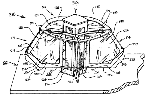
Figure 1 is a perspective view of a desktop-type ventilation system according
to the
present invention in the downward discharge version;
Figure 2 is an exploded view of the primary hood related components of a
desktop-type
ventilation system according to the present invention;
Figure 3 is an exploded view of a fume hood and a ventilation hub according to
the
present lnventlon;
Figure 4 is an exploded view of a ventilation hub according to the present
invention;
Figure 5 is an exploded view of an upper ventilation coupling according to the
present
lnventlon;
Figure 6 is a plan view of a ventilation hub according to the present
invention;
Figure 7 is a plan view of a ventilation hub anchor plate according to the
present
Invention;
Figure 8 is a plan view of a ventilation hub bottom anchor plate according to
the present
invention;
Figure 9 is a top plan view of a desktop-type ventilation system with downward
exhaust
according to the present invention;
21512771.1
CA 02541208 2006-03-28
Figure 10 is an elevation view of a desktop-type ventilation system according
to the
present invention;
Figure 11 is a sectional view of a desktop-type ventilation system according
to the present
invention taken generally along line 11-11 of Figure 9, which illustrates the
present invention
connected to a primary ventilation system beneath the worktop;
Figure 12 is a sectional view of a desktop-type ventilation system according
to the present
invention taken generally along line 12-12 of Figure 9;
Figure 13 is a sectional view of a desktop-type ventilation system according
to the present
invention taken generally along line 13-13 of Figure 10;
1 o Figure 14 is a partially exploded view of a side wall extension panel for
directing air
towards the ventilation hub, and separating each adjacent work area from one
another;
Figure 15 is an enlarged perspective view of an adjustable channel for
attachment to rear
edge of side wall panel according to the present invention;
Figure 16 is an enlarged perspective view of a spacer wall for attachment to
the bottom
edge of the side wall panel according to the present invention;
Figure 17 is a perspective view of a plurality of fume hoods according to the
present
invention, with side wall panel extensions, work trays, and adjustable shelves
according to the
present mventlon;
Figure 18 is a perspective view of the housing wall panel components of a
bench top hood
2o system with fume hoods according to the present invention;
Figure 19 is a perspective view of bench top work trays according to the
present
invention;
Figure 20 is a front elevation view of a plurality of desktop-type ventilation
systems
according to the present invention connected to a primary ventilation system
below a
25 worksurface;
Figure 21 is a plan view of a plurality of desktop type ventilation systems
connected to a
primary ventilation system below a worksurface;
21512771.1
CA 02541208 2006-03-28
Figure 22 is an exploded view of the ventilation hub and anchor plate above
and below a
worksurface of a desktop-type fume hood system according to the present
invention;
Figure 23 is an exploded view of a modular duct system for coupling a primary
ventilation
system to a desktop-type ventilation system of the present invention.
Figure 24 is a front elevation view of two desktop-type ventilation systems
according to
the present invention with modular fit together ventilation exhaust components
mounted atop the
ventilation hub and connected to a primary ventilation system overhead;
Figure 25 is a front elevation of a desktop-type ventilation system with air
purifying
system installed atop the ventilation hub according to the present invention;
and,
1o Figure 26 is a top plan view of an air purifying system of a desktop-type
ventilation system
according to the present invention.
DETAILED DESCRIPTION OF THE INVENTION
[0024] At the outset, it should be appreciated that while the present
invention is described
with respect to what is presently considered to be the preferred embodiments,
the invention is not
limited to the embodiments specifically recited herein. In the detailed
description that follows,
like drawing numbers on different drawing views are intended to identify
identical structural
elements of the invention. The terms/phrases "desktop" and "desktop-type" as
they relate to
ventilation systems are intended to refer to ventilation systems, fume hoods,
etc., that are
compact, portable, and primarily configured for placement on desktops,
benchtops, and similar
2o work surfaces, etc. The present invention may include several features
described in U.S. Patent
Application No. 11/013,169, which application is incorporated herein by
reference in its entirety.
(0025] Referring now to the figures, Figures 1-3, 10-12, 17, 20, 24 and 25
illustrate
desktop-type ventilation system 510 according to the present invention placed
on work surface
512. Desktop-type ventilation system 510 broadly comprises at least one fume
hood enclosure
514 and ventilation hub 516. Ventilation hub 516 is provided to connect one or
more fume hood
enclosures 514 to primary ventilation system 620 (see Figures 21 and 24),
e.g., a primary
ventilation system of a building or other air filtering system, such that an
area of low pressure may
be created under the fume hood. The area of low pressure tends to draw air
into fume hood
21512771.1
CA 02541208 2006-03-28
enclosure 514 and evacuates the air in the direction of the arrows (see
Figures 10 and 11). In one
embodiment, ventilation hub 516 is detachably securable to work surface 512
(particularly
wherein utility lines are not installed and wherein the system is vented
downward). Preferably,
ventilation hub 516 is centrally disposed upon work surface 512, e.g. a
desktop, and is connected
to primary ventilation system 620 by means of lower ventilation coupling 518
(shown in Figure 4,
10, 11, and 20) as it passes through aperture 590 (see Figure 22).
Alternatively, as illustrated in
Figures 5, 23 and 24, ventilation hub 516 may be secured to primary
ventilation system 620 by
means of upper ventilation coupling 520.
[0026] Referring specifically now to Figures I-3, and 9-12, each fume hood
enclosure 514
1o generally comprises front wall panel 522, rear wall 524, which is a wall of
the ventilation hub, side
wall panels 526, and top wall panel 528. In one embodiment, rear wall 524,
side wall panels 526
and top wall panel 528 can be planar, flat, and can have lights, whereas front
wall panel 522 is
arcuate and curved. Front wall panel 522, rear wall 524, side wall panel 526
and top wall panel
528 are detachably securable to each other and to ventilation hub 516, such
that the desktop-type
ventilation system 510 may be readily disassembled. In an embodiment, front
wall panel 522 is
detachably securable to side wall panels 526 and top wall panel 528. Front
wall panel 522 serves
as a viewing shield to allow individuals to view their work under the hood
while simultaneously
preventing/minimizing injury that may occur. With the exception of front wall
panel 522, which is
fully optically clear in one embodiment, top wall panel 528 and side wall
panels 526 of the fume
2o hood enclosure preferably contain viewing panels 683, which can be made
from optically clear
material, secured within a frame formed or constructed from heat, shock, and
chemically resistant
materials. To accomplish this the fume hood side wall 526 and top panels 528
can be framed
allowing a light transmitting material to be inserted. In a one embodiment,
opadue portions of
walls can be formed from a cellulose fiber reinforced phenolic resin core
material, such as Trespa
25 AthlonT~', currently available from Trespa North America of California. It
should be appreciated,
however, that the specific materials from which the walls of the fume hood may
be formed may
vary according to the intended use of the desktop-type ventilation system, for
example, metals,
plastic, glass, fiberglass, resins, wood, or combinations thereof, etc., can
be used.
21512771.1
CA 02541208 2006-03-28
- 10-
[0027] Front wall panel 522 (viewing shield) is provided to prevent/minimize
injury to
individuals working under the fume hood and defines workstation opening 530.
As seen in Figure
2, front wall panel 522 comprises front wall upper edge 532, front wall side
edges 534, and front
wall lower edge 536. Front wall upper edge 532 and front wall lower edge 536
are arcuate and
front wall upper edge 532 has a radius that is smaller than that of front wall
lower edge. Front
wall upper edge 532 is configured for receivable fit within arcuate groove 570
(see Figure 12) of
top wall panel 528. Front wall side edges 534 are configured for receivable
fit on the bottom lip
550 of the front edge of hood side wall panel 526 and the side wall edges 534
may also have
protrusion 506 over the center line of hood side wall panel 526 such that a
centering hole within
l0 front wall panel 522 is possible. Protrusion 506 mates with a corresponding
protrusion 506 of
adjacent front wall side edge 534. In the embodiment illustrated, protrusion
506 comprises an "s"
edge and includes pinhole 508 for receiving a pin to assure that front wall
panel 522 is correctly
placed. A pin or hand operated fastener may be used to detachably secure front
wall panel 522 to
the front edge of side wall panel 526 (see Figure 3). In one embodiment, front
wall panel
(viewing shield) 522 extends from the top of the fume hood to a position that
is generally
intermediate the vertical height of the fume hood. In another embodiment,
front wall panel
(viewing shield) 522 is wholly transparent and formed from heat, shock, and
chemically resistant
materials, and more preferably, is formed from a lightweight, transparent
acrylic or polycarbonate;
it should be appreciated, however, that the specific materials from which
front wall panel 522 may
2o be formed may vary with the intended use of the desktop-type ventilation
system 510. Front wall
panel (viewing shield) 522 can be molded to maintain an arcuate and outwardly
sloping
configuration. The arcuate and sloped nature of the front wall panel (viewing
shield), which
slopes outward from front wall upper edge 532 to front wall lower edge 536,
tends to increase the
work area under the fume hood and improves air flow, field of view/line of
sight by reducing glare
from various angles, and promotes the efficient and safe use of the fume hood
(ergonomics). The
arcuate and sloped nature of the front wall (viewing shield) 522 also acts to
increase the amount
of light that is able to reach the work surface. While front wall (viewing
shield) 522 is illustrated
21512771.1
CA 02541208 2006-03-28
as being devoid of a sash member for substantially closing the front wall when
not in use, the front
wall may be configured to comprise such a feature.
[0028] Side wall panels 526 can be configured to comprise metal track 560
comprising
means for adjustably securing the sidewalk to the ventilation hub. Metal track
560 is disposed
along the rear vertical edge of hood side wall panel 526 and comprises
adjustable securing means
including but not limited to indexed fasteners 509 which allow the hood side
wall panel 526 to be
adjustably secured within indexed recess track 554 of square channel edge 558
of the ventilation
hub 516. Side wall panels 526 diverge with respect to one another from rear
wall 524 to front
wall (viewing shield) 522. The divergent configuration of side wall panels 526
acts to funnel air
1o drawn into the fume hood toward ventilation hub 516 such that air is more
efficiently and
effectively evacuated from below the fume hood enclosure. Side wall panels 526
comprise side
wall front edge 538, side wall rear edge 540, side wall bottom edge 542 and
side wall top edge
544. Side wall front edge 538 comprises sloped portion 546, anchor post
devices 549 and notch
portion 550. The angle of sloped portion 546 generally correlates with the
slope of front wall
I5 (viewing shield) 522. Side wall front edge 546 contains two identical
fasteners 549 which are
securely anchored into side wall front edge 546 and are utilized to align and
secure the front wall
(viewing shield) 522. Cutaway portion 548 generally corresponds with
workstation opening 530
and is generally provided to reduce the footprint of the fume hood and
increase the area of the
work space. Cutaway portion 548 also tends to promote more efficient and safe
use of the fume
2o hood (ergonomics), provide reductions in the weight of the fume hood side
wall panel, and tends
to increase the field of view/lines of sight to the work area such that
individuals, e.g., instructors,
may more effectively monitor the work area. Proximate the interface of sloped
portion 546 and
cutaway portion 548 is notch portion 550. Notch portion 550 is provided for
receiving front wall
panel 522 and providing a flush front appearance. Attaching front wall panel
522 using notch 550
25 on side wall panel 526 can be accomplished in various other way that
include using screws that
are threaded through front wall panel 522, using and adhesive to secure front
wall panel 522 to
side wall panel 526, or other similar attachment means are considered within
the spirit and scope
of the invention. Also inserting front wall panel 522 into a groove on side
wall panel 526 is
21512771.1
CA 02541208 2006-03-28
- 12-
another possible attachment method. Front wall panel 522 may be secured to the
side wall posts
549 by means of appropriate fasteners such as the anchor posts 549, screws,
threaded bolts,
pushpins, or may be held in place by a tension force, e.g., by oppositely
directed forces of adjacent
front wall panels. Side wall rear edge 540 can be routed and beveled to accept
the detachable rear
adjustment track 560 which can facilitate side wall panel 526 to be hung and
secured on
ventilation hub 516. Various fasteners may be utilized to attach rear
adjustment track 560 to side
wall rear edge 540. Side wall bottom edge 542 is generally provided to receive
a vertical
adjustable spacer wall 651 (see Figure 16). The vertical adjustable spacer
wall 651 is available in
at least one height and may include many heights to accommodate the height
adjustment ranges of
to the side wall panel 526 for contacting desktop 512 and may include rubber
feet for preventing
movement of the bottom surface thereon or may include adjustment and anchorage
holes to affix
spacer wall 651 to work tray 500 (Figure 17 and 19) and to side wall panel
526. Spacer wall 651
enables side wall panel 526 to be adjust vertically to accommodate various
experiments or users.
The number of adjustment holes 503 can be increased incrementally and can be
varied.
Adjustment holes 503 in spacer wall 651 and side wall panel 526 are intended
to be aligned and
pushpin or another similar securing means is used to hold the adjusted wall in
the desired position.
Modular work trays 500 (see Figure 17 and 19) surround the perimeter of the
ventilation hub and
the front circumference of the work tray can in some aspects match the bottom
edge radius of the
front panel 522. Work tray 500 is attached to ventilation hub 516 and to
spacer wall 651 at
2o attachment track 504 using a fastening means that can include, but is not
limited to: threaded
bolts, push pins, and screws. Side wall top edge 544 is generally provided for
supporting top wall
panel 528. Side wall top edge 544 can be arranged to slope upward from the
rear of the fume
hood to the front of the fume hood (see Figures 10, 11 and 12) and comprises
two posts 549
anchored within the side wall for securing top wall panel 528. Various other
securing means can
be substituted for posts 549 and it should be appreciated that posts 549
comprise only one of
many viable securing means known to one of ordinary skill in the art.
[0029] Ventilation hub 516, in the embodiment illustrated is shown as being
rectangular in
shape. Rear wall vent outlet orifice 524 corresponds to the rectangular shape
of ventilation hub
21512771.1
CA 02541208 2006-03-28
- 13 -
516. Ventilation hub 516 may be shaped other than rectangular, such as oval,
circular, triangular,
etc.
[0030 Top wall panel 528 comprises top wall front edge 564, top wall rear edge
566 and
top wall side edges 568. Top wall side edges 568 can be configured to include
an "s" shape
protrusion 506. Protrusion 506 having the "s" shaped pattern can comprise
pinhole 508 for
positioning the top panel correctly over the hood side wall panels 526. Top
wall front edge 564 is
shown to be arcuate and includes arcuate groove 570 on its interior surface.
Arcuate groove 570
(see Figure 11) can be provided to accept front wall upper edge 532 of front
wall (viewing
window) 522 therein. Proximate and along the front edge are a series of
orifices 572 for drawing
air into the flame hood. Orifices 572 tend to draw air into the fizme hood
from above such that
any air collecting under the fi~me hood near top wall panel 528 is evacuated.
Top wall rear edge
566 generally corresponds with the width and shape of ventilation hub 516. Top
wall side edges
568 diverge with respect to one another from top wall rear edge 566 to top
wall front edge 564
and generally correspond with diverging side wall panels 526. Top wall panel
528 is configured
to be secured to top edges 544 of side wall panels 526. Thus, top wall panel
528 is configured for
directing and causing air to be funneled toward ventilation hub 516 and more
specifically into rear
wall vent outlet orifice 524. It should be appreciated that rear wall vent
outlet orifice 524 may be
divided into a plurality of orifices. While in one embodiment the top wall is
opaque, it may be
configured to comprise a viewing window therein, or may comprise a wholly
transparent material
2o for allowing light to pass for illuminating the work area.
[0031] Referring more specifically now to Figures l, 3, 4-8, l0, 11, 22 and
23, ventilation
hub 516 is provided for connecting the fume hoods to a primary ventilation
system 620, such that
air may be evacuated from the fume hoods) 514. Generally air enters the fume
hood area at
workstation opening 530. Air may also enter through orifices 572. Ventilation
hub 516 broadly
comprises ventilation core 574 (see Figure 4), which is configured for
securing lower ventilation
coupling 518, upper ventilation coupling 520 and/or ventilation cover 575. In
one embodiment,
ventilation core 574 is formed of stainless steel or other appropriate
material and comprises at
least one vent 524, which can comprise a screened material formed from
stainless steel, and more
21512771.1
CA 02541208 2006-03-28
- 14-
specifically, 50-60% open mesh, but the percentage of open mesh can vary.
Other materials used
to construct ventilation core 574 can include, but is not limited to other
metals, plastic, glass,
fiberglass, resins, wood, or combinations thereof, etc.
[0032] Ventilation hub S l 6 can also comprise rectangular channels 558 and in
one
embodiment four channels 558 are used and are substantially mated to
ventilation hub base anchor
plate 588. Each channel can provide anchorage to the hub base anchor plate 588
and also
provides for hood wall adjustability with one or more recessed tracks 554.
This arrangement can
also provide a passageway for electric power lines 555, data communication
lines 556, and/or
mechanical service lines 557. Electrical outlets 561 and fixtures for these
various lines, such as
to mechanical service fixture 559 can be installed on the exterior of
ventilation hub 516. Where
ventilation core 574 comprises a plurality of vents 524 and fewer fume hoods
are secured to the
to the ventilation hub 516, vents 524 may be closed utilizing an appropriately
fitting cover, if
desired. In a one embodiment, the area of vents 524 is large such that static
pressure drops are
lowered. As a result, the fume hoods may be safely operated using low velocity
fans and blowers,
which can draw air into the hood at velocities as low as 35 cubic feet per
minute/hood. The
ability of the ventilation system of the present invention to utilize low
velocity fans lowers fume
hood face velocities, noise levels and reduces the volume of air that is drawn
into the fume hoods,
which can result in significant cost savings with regard to heating/air
conditioning.
[0033 Ventilation core 574 is adapted to receive channeling insert 578
therein, which acts
2o to more efficiently and effectively draw air from within fume hood
enclosure 514. In the
embodiment illustrated, channeling insert 578 (see Figure l 1 ) comprises a
stainless steel screen
that has a cross-sectional shape forming a cross. The cross structure forms
individual air
passages, one for each vent 524, within the ventilation core 574. Channeling
insert 578 is
designed to reduce turbulence within the ventilation core 574. It should be
appreciated that while
channeling insert 578 is illustrated as having a cross-sectional shape in the
form of a cross, the
cross-sectional shape of the channeling insert will depend upon the number of
vents 524 disposed
in ventilation core 574. A further benefit provided by channeling insert 578
is that it tends to
prevent individuals from viewing, through vents 524, work areas under other
fume hoods that
2ls~z~~~.~
CA 02541208 2006-03-28
-15-
may be secured to ventilation hub S l6. It should be appreciated that while
ventilation core 574 is
illustrated as comprising a rectangular parallelepiped, the ventilation core
may be shaped
otherwise, e.g., cylindrical, polygonal, etc., and its related components,
e.g., upper and lower
ventilation couplings, side and front wall panels, etc., may be
correspondingly configured for
mating fit therewith. In a cylindrical embodiment, channeling insert 578 may
comprise a cross-
sectional shape in the form of a cross, or may comprise an Archimedes screw-
type device
configured for rotation within ventilation core 574 under the force of air
being forced
therethrough, e.g., as by primary ventilation system 620.
[0034] In one embodiment, the desktop-type ventilation system 510 of the
present
invention may be detachably mounted to primary ventilation system 620 with
lower ventilation
coupling 518 that passes through a desktop or work surface (See Figures 20-
23). In such
instance, the desktop-type ventilation system 510 may be secured to the
primary ventilation
system 620 by means of lower ventilation coupling 518, which in this case
comprises aperture 590
and anchor plates 588 and 600. In such configuration, the upper end of
ventilation core 574 may
1 s be closed off by ventilation cover 575. As illustrated in Figures 4 and
19, lower ventilation
coupling S l 8 will slip through aperture 590 of ventilation hub base anchor
plate 588 and opening
590 in upper surface mounting plate 600. Coupling 518 will affix to
ventilation collar 682 (see
Figure 4) of the of ventilation core 574 through fixed desktop or work surface
512. Lower
ventilation anchor plate 588 corresponds to the cross-sectional shape of
ventilation core 574
2o shown in figure 4, 6, 13 and 22 and generally comprises formed angles 586
attached to base plate
588. Base plate 588 comprises aperture 591 configured to allow passage of
electrical, data lines
and mechanical services and for accepting passage of duct coupling 518
therein. Base plate 588
further comprises a plurality of throughbores 594 for securing the lower
ventilation anchor plate
coupling to a desktop or work surface 512. Duct coupling 518 generally
comprises annular ring
25 portion 595 and duct receiving portion 596, which is configured for
connection to a duct of a
primary ventilation system 620 or other filtering system and to the lower
ventilation collar 682 of
ventilation core 574. Annular ring portion 595 may be detachably secured to
bottom face of
worktop 512 by appropriate fastening means. The top portion of 596 of coupling
518 shown on
zis~z~m.~
CA 02541208 2006-03-28
- 16-
Figure 4 is configured to slip over the exterior of the lower ventilation
collar 682 of ventilation
core 574. In one embodiment, each of the formed angles 586 includes
appropriate means for
detachably securing ventilation core 574 thereto, for example, throughbores
582 for receiving
threaded fasteners, or threaded throughbores can be used to accept threaded
fasteners.
[0035] Alternatively, where ventilation of the fume hood enclosures is to be
provided by,
for example, an overhead primary ventilation system 620 (Figure 24), upper
ventilation coupling
520 (Figure 5 and 23) may be utilized. As shown in Figures S, 23 and 24 upper
ventilation
coupling 520 generally comprises upper plate 598, lower plate 599 and duct
coupling 592. Upper
plate 598 and lower plate 599 comprise apertures 625 and 601 for passing duct
receiving portion
to 596 of duct coupling 592 therethrough. Annular ring portion 595 of duct
coupling 592 may be
detachably secured to upper plate 598 and lower plate 599 by appropriate
fastening means.
Upper plate 598 can be made from Trespa Athlon '"'. Lower plate 599 can be
formed from
stainless steel and further comprises angle members 602 having throughbores
582 for securing the
upper coupling 520 to the ventilation core 574. Upper ventilation coupling 520
may also be
I5 configured to comprise one or more electrical outlets and/or illumination
devices (not shown) for
illuminating the work area under each fume hood enclosure 514. For example,
upper ventilation
coupling 520 may comprise four electrical outlets and/or four illumination
devices where the
desktop-type ventilation system 5'10 comprises four fume hoods and the top
walls 528 of each
fume hood comprise a viewing window. As illustrated in Figures 23 and 24,
upper coupling 520
2o may also be configured for accepting duct coupling 592 comprising threaded
duct receiving
portion 596, for accepting threaded coupling 610. Threaded coupling 610 is
adapted for mating
fit with one or more modular ducts 611 (Figure 24), which connect the desktop-
type ventilation
system 510 with the primary ventilation system 620. Sleeve 612, which may
comprise an
aesthetically pleasing material such as stainless steel mesh, is provided for
covering modular ducts
25 611. Multiple length sleeves 612 and multiple length modular ducts 611 are
attached with at least
one phenolic disk mating coupling 630.
[0036] The present invention is generally configured to be easily set up and
broken down
after use. After side walls 526, top walls 528, and front walls 522 have been
appropriately
21512771.1
CA 02541208 2006-03-28
- 17 -
secured to one another by means of fasteners, which are made up of protrusion
506 and pinhole
508 cooperating with anchor post 549 onto ventilation hub 516, a user need
merely disengage
protrusion 506 from anchor post 549 (which can be can be designed to be
removed without any
tools), and remove twelve panels to a cart specifically designed for storage
of hood system panel
components (Figure 18). Other fastener alternatives can include screws,
rivets, pins, etc.
Thereafter, the ventilation hub 516 provides general ventilation, if desired,
and also serves to
house all data, electrical, and plumbing services and service fixtures within
channels 558 and also
provides slotted recessed vertical tracks for hanging shelves 640 or hanging
baskets 641 (see
Figures 4, 13 and l7). Slotted tracks 554 provide a structure that allows the
accessories to be
to height adjustable. Where a plurality of fume hoods are secured to the
ventilation hub 516, the
desktop-type ventilation system 510 comprises a pod, or cluster, of fume hoods
utilizing a
common connection to primary ventilation system 620 (See Figure 4, 20, and
24). Disassembly
of the desktop-type ventilation system 510 is generally the opposite of
assembly. Generally, the
frst step is to remove front wall fasteners 551 such that front walls 522 may
be removed. As
I5 illustrated in Figure 4, 13, and 17, after removal of the front walls, side
walls, and top walls, the
hanging baskets 641 and shelves 640 can be left in place or adjusted
vertically within the slotted
track system of the rectangular channels 558. After disassembly and when the
desktop-type
ventilation system 510 is not in use, the ventilation hub structure 516
remains in place to provide
convenient service fixture locations and storage devices as well as lighting
overhead.
20 [0037] As illustrated in Figure 25, a desktop-type ventilation system
according to the
present invention may also be configured to comprise self contained air
purifying unit 690. Self
contained air purifying unit 690 is generally configured to be secured atop
ventilation hub 516.
The self contained air purifying system generally allows fume hoods to be
added to a laboratory
without the need for newly constructing a central ventilation system or
modifying a current central
25 ventilation system. Self contained air purifying unit 690 can include a
motorized exhaust air
filtration system (not shown), one or more light sources 696, one or more
electronic displays 698
and controls 700. Individual users can turn on the flat screen display panels
698 in the air
purifying system from a membrane control pad located within the nearest set of
vertical channels
21512771.1
CA 02541208 2006-03-28
-18-
of the ventilation hub. One channel can provide users access to individual
touch pads at opposite
adjacent sides of the vertical wall panel, and the same user features exist at
opposite side of
assembly.
[0038] Light sources 696 can be disposed above the top wall panels and
parallel therewith
such that the work areas below the fume hood enclosure can be illuminated. In
one embodiment
the lights are disposed in the underside panels at the same angle of
inclination as the hood top
panels over which it cantilevers. Electronic displays 698 are generally
provided for more
efficiently and effectively providing instruction in an educational type
setting. Electronic displays
698 can be communicatively connected to a computer such that software programs
may be
to viewed thereon. Electronic displays 698 can be disposed at an angle to
facilitate comfortable
viewing through top wall panel 528 while an individual is working underneath a
particular fume
hood enclosure. Software programs used in association with the electronic
display panels can
include instructional materials for a particular experiment. Software programs
may be modified
by an instructor and may be adapted to a particular unidueness or object of
the experiment
undertaken. Software programs may be individually loaded into a workstation at
control panel
700 or may be communicated to a workstation from a central location by means
of a data line
passing through the ventilation hub. Each operator of the fume hood in the
laboratory can receive
information on the lab experiment from an instructor modified or a standard CD
of the lab
experiment to be undertaken which is loaded into the system from one main
console of the lab and
2o which can be utilized by the student from the overhead console ventilation
and which the student
may interact with the displayed information either at the air purifying system
or from within the
individual fume hood work area while performing the experiment at the vertical
channel nearest
the operator. Another alternative is to provide a lab-assist software card
unidue for the
experiment that will be undertaken into the air purifying system and interact
with the displayed
25 information either at the air purifying system or from within the
individual fume hood work area
at the vertical channel within ventilation hub nearest the operator.
[0039] Alternatively, each workstation may comprise wireless means for
communicating
information to be displayed on electronic display panels 698. Software can be
programmed to
21512771.1
CA 02541208 2006-03-28
- 19-
comprise an active guide for experimentation and may help to identify
experimental milestones or
problem areas that may be encountered, help identify causes and cures of
problems to help
students remain on track and can help students work safely. Additionally, the
electronic displays
can be programmed to display a timed sequence of events. The timed sequence of
events enable a
s student to log information at key points during an experimental process, and
at the end, the
software can down-load and track, at timed points, where notes were taken and
correlate the
experimental process in pictured screens to the notes.
[0040 A self contained air purifying system can be powered by means of utility
lines that
pass through a utility conduit contained within the ventilation hub. The air
purifying system can
to comprise specialized filtration and chemical absorption assemblies for
filtering specific targets.
Control panels 700 are provided at each workstation such that the filtration
system, light sources
692 (off/low/high) and electronic displays 698 may be controlled. The device
may be configured
to comprise switches for operating the air purifying filtration system at
point of use in either a low
exhaust mode when mildly hazardous compounds are being used, or at high
exhaust volume mode
15 when active experimentation is undertaken. It is also possible to operate
all air purifying system
systems within the lab from an instructor control panel in the laboratory with
similar low/high/off
capability. Digital membrane control pad 702 may also be provided in the
ventilation hub to
operate the purifying system, toggle light sources, or control the computer
and/or electronic
display.
20 [0041] Thus, it is seen that the aspects of the present invention are
efficiently obtained,
although modifications and changes to the invention should be readily apparent
to those having
ordinary skill in the art, which modifications are intended to be within the
spirit and scope of the
invention as claimed.
21512771.1
CA 02541208 2006-03-28
[0042] Parts List
500 Work tray
502 Fasteners
504 Side wall panel attachment track
506 Protrusion
508 Pinhole
509 Indexed Fastener
510 Desktop-type ventilation system
512 Work surface/desktop
514 Fume hood enclosure
516 Ventilation hub
518 Lower ventilation duct coupling
520 Upper ventilation coupling
522 Front wall panel/ viewing window
524 Rear wall- vent outlet orifice
526 Side wall panel
528 Top wall panel
530 Workstation opening
532 Front wall upper edge
534 Front wall side edge
536 Front wall lower edge
538 Side wall front edge
540 Side wall rear edge
542 Side wall bottom edge
544 Side wall top edge
546 Sloped portion of side wall front edge
548 Sloped and vertical cut-away portion
of side wall front edge
549 Shoulder anchor devices on side wall
front and top edges
550 Notch portion/bottom lip on front of
hood side wall
554 Recess track of square channel edge
555 Electric power lines
556 Data communication lines
557 Mechanical service lines
21512771.1
CA 02541208 2006-03-28
-2l -
558 Channel
559 Mechanical service fixture
560 Detachable rear adjustment track
561 Electrical outlet
564 Top wall front edge
566 Top wall rear edge
568 Top wall side edge
570 Arcuate groove on interior surface
of top wall front edge
572 Orifices (for air)
574 Ventilation core
575 Ventilation cover
578 Channeling insert
582 Throughbores
586 Formed angles attached to anchor plate
588 Base anchor plate for ventilation
590 Aperture
591 Opening in base anchor plate
592 Duct coupling
594 Throughbores
595 Annular ring portion
596 Duct receiving portion
598 Upper plate
599 Lower plate
600 Under surface mounting plate
601 Aperture within metal plate
602 Formed angle member
610 Threaded coupling
611 Modular ducts
612 sleeve
620 Primary ventilation system
625 Aperture within upper coupling
630 Phenolic disk mating coupling
640 Shelf
641 Basket
21512771.1
CA 02541208 2006-03-28
-22-
651 Vertical adjustable
spacer wall
682 Ventilation collar
683 Side and top wall viewing
panel
690 Self contained air
purifying unit
692 Light Source
698 Electronic Display
700 Control Panel
702 Membrane control panel
21512771.1