Note: Descriptions are shown in the official language in which they were submitted.
CA 02541304 2006-03-30
Attorney Docket 56.0854
Non Provisional Application
A SYSTEM FOR PRECISELY CONTROLLING A DISCHARGE
RATE OF A PRODUCT FROM A FEEDER BIN
FIELD OF THE INVENTION
[0001] The present invention relates generally to a system for precisely
controlling the discharge rate of a product from a feeder bin, and more
particularly to
such a system which continually monitors the discharge rate of the product and
automatically adjusts the discharge rate based on measurements of the product.
BACKGROUND
[0002] In the oil well drilling and production industry, viscous fluids or
gels
are often pumped into a well to initiate and propagate underground fractures
in order to
increase the productivity of the well. Such operations are commonly referred
to as well
fracturing operations.
[0003] The most common method currently used for the continuous on-site
preparation of well fracturing gels involves combining a polymeric material
with a carrier
fluid, such as a hydrocarbon material, in a feeder to form an aqueous solution
of the
polymeric material. The aqueous solution is then discharged from the feeder
and
combined with another substance to form a gel. Such a gel preparation method
is
desirable in that the amount of the aqueous solution that is discharged from
the feeder can
be precisely controlled, and therefore the resultant gel and its properties
can be precisely
controlled as well. A drawback of this gel preparation method is that the use
of the
hydrocarbon carrier fluid, which in many cases is diesel, causes environmental
concerns.
[0004] Therefore, it is desirable to eliminate the carrier fluid in the
feeder, and
feed a dry mix of polymeric material from the feeder. However, the flow
properties of a
dry mix are much less predictable than that of an aqueous solution. This is
due to
variations in the packing or compactness of the dry mix, the moisture content
of the dry
mix, and/or the amount of the dry mix in the feeder, among other variations in
the
environment of the dry mix or other variations in the dry mix itself.
[0005] Existing system for discharging a dry mix of a polymeric material
from a feeder to form a fracturing gel are described in U.S. Patent Nos.
5,426,137 and
5,382,411 to Allen; and U.S. Patent No. 5,190,374 to Harms. These systems
include a
1
CA 02541304 2006-03-30
Attorney Docket 56.0854
Non Provisional Application
metering screw or an auger that needs to be calibrated for each dry mix of
material that it
discharges. However, after the initial calibration of the discharge device,
these systems
do not include any quality control during the process of discharging the
polymer. As
such, the actual amount of dry mix that is discharged from the feeder is not
measured or
controlled.
[0006] Instead, the precision and reliability of these systems is dependent
solely on the repeatability of the screw/auger to deliver the same amount of
dry mix for
each turn of the screw/auger. Therefore, using these methods, variations in
the flow
properties of the dry mix are not taken into consideration. As a result, the
properties of
the resultant gel that is produced from the dry mix cannot be precisely
controlled.
Accordingly, a need exists for a method of precisely controlling an amount of
a dry mix
of material that is discharged from a feeder.
SUMMARY
[0007] In one embodiment, the present invention is a system for precisely
controlling a discharge rate of a discharged product that includes a feeder
bin having an
internal chamber; a product disposed in the internal chamber of the feeder
bin; and a
discharge device that receives a portion of the product and discharges it at a
discharge
rate from the feeder The system also includes a control system that
continually monitors
the discharge rate of the discharged product and automatically adjusts the
discharge rate
based on measurements of the product.
[0008] In another embodiment, the present invention is a system for precisely
controlling a discharge rate of a discharged product that includes a feeder
bin having an
internal chamber; a dry mix of material disposed in the internal chamber of
the feeder
bin; and a discharge device that receives a portion of the dry mix of material
and operates
at an adjustable speed to discharge the dry mix of material at a discharge
rate from the
feeder. The system also includes a measurement system that continually makes a
measurement indicative of a weight of the discharged dry mix of material; and
a control
system that receives a feedback signal indicative of the weight of the
discharged dry mix
of material and automatically adjusts a speed of operation of the discharge
device based
2
CA 02541304 2011-03-08
51650-39
on the feedback signal in order to precisely control the discharge rate of the
discharged dry mix of material.
[0009] In yet another embodiment, the present invention is a method of
precisely controlling a discharge rate of a discharged product that includes
providing
a feeder bin having an internal chamber; inserting a dry mix of material into
the
internal chamber of the feeder bin; and operating a discharge device at an
adjustable
speed to discharge portions of the dry mix of material at a discharge rate
from the
feeder. The method also includes making a measurement indicative of a weight
of
the discharged portions of the dry mix of material; and providing a control
system that
receives a feedback signal indicative of the weight of the discharged portions
of the
dry mix of material and automatically adjusts the speed of operation of the
discharge
device based on the feedback signal in order to precisely control the
discharge rate of
the discharged portions of the dry mix of material.
In still another embodiment, there is provided a system for precisely
controlling a discharge rate of a discharged product comprising: a feeder bin
having
an internal chamber; a dry mix of material disposed in the internal chamber of
the
feeder bin; a discharge device that receives a portion of the dry mix of
material and
operates at an adjustable speed to discharge said portion of the dry mix of
material
from the feeder; a measurement system that continually makes a measurement
indicative of a weight of the feeder bin; and a control system that receives
an input
discharge rate setpoint, an input of a calibration curve comprising a
representation of
a speed of operation of the discharge device as a function of a discharge rate
of the
dry mix of material, and a feedback signal indicative of the weight of the
feeder bin,
wherein the control system calculates a theoretical speed of operation based
on the
input discharge rate setpoint and the calibration curve, determines an actual
discharge rate based on the measurement indicative of the weight of the feeder
bin,
calculates a correction factor that is equal to the input charge rate setpoint
divided by
the actual discharge rate, calculates a speed setpoint that is equal to the
theoretical
speed of operation multiplied by the correction factor, and automatically
adjusts the
3
CA 02541304 2011-03-08
51650-39
adjustable speed of the discharge device based on the calculated speed
setpoint in
order to precisely control the discharge rate of the discharged dry mix of
material.
In still another embodiment, there is provided a method of precisely
controlling a discharge rate of a discharged product comprising: providing a
feeder
bin having an internal chamber; inserting a dry mix of material into the
internal
chamber of the feeder bin; operating a discharge device at an adjustable speed
to
discharge portions of the dry mix of material from the feeder; making a
measurement
indicative of a weight of the dry mix of material in the feeder bin; providing
a control
system that receives an input discharge rate setpoint, an input of a
calibration curve
comprising a representation of a speed of operation of the discharge device as
a
function of a discharge rate of the dry mix of material, and a feedback signal
indicative of the weight of the feeder bin; calculating a theoretical speed of
operation
based on the input discharge rate setpoint and the calibration curve;
determining an
actual discharge rate based on the measurement indicative of the weight of the
feeder bin; calculating a correction factor that is equal to the input charge
rate
setpoint divided by the actual discharge rate; calculating a speed setpoint
that is
equal to the theoretical speed of operation multiplied by the correction
factor; and
automatically adjusting the adjustable speed of the discharge device based on
the
calculated speed setpoint in order to precisely control the discharge rate of
the
discharged dry mix of material.
BRIEF DESCRIPTION OF THE DRAWINGS
[00010] These and other features and advantages of the present invention will
be better understood by reference to the following detailed description when
considered in conjunction with the accompanying drawings wherein:
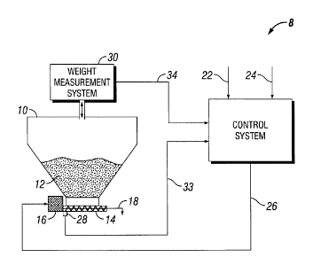
[00011] FIG. 1 is a schematic representation of a system for precisely
controlling a discharge rate of a dry mix of material from a feeder bin
according to
one embodiment of the present invention; and
3a
CA 02541304 2011-03-08
51650-39
[00012] FIG. 2 illustrates a method of determining an actual discharge rate of
the dry mix of material using the system of FIG. 1.
DETAILED DESCRIPTION OF EMBODIMENTS OF THE INVENTION
[00013] As shown, embodiments of the present invention are directed to a
system for precisely controlling a discharge rate of a dry mix of material
from a feeder
bin. In one embodiment, the dry mix is a polymeric material which is
discharged from
a feeder bin and combined with a further substance to form a well fracturing
gel.
3b
CA 02541304 2006-03-30
Attorney Docket 56.0854
Non Provisional Application
[00014] FIG. 1 shows a feeder bin 10 having an internal chamber, which
receives a dry mix of a product 12. As used herein, the phrase "dry mix"
generally refers
to a powder, a collection of granules, or another collection of solid
materials. Although
any appropriate feeder bin may be used in conjunction with the present
invention, in the
depicted embodiment the feeder bin 10 includes a relatively large upper end,
and a
generally tapered lower end which funnels the dry mix of product 12 to a
discharge
device 14. The discharge device 14 may be a metering screw, an auger, or any
other
appropriate device for receiving a portion of the dry mix of product 12 and
discharging it
(as represented by arrow 18.) from the feeder bin 10. As shown, the feeder bin
10 also
includes a power supply 16 for powering the discharge device 14. The power
supply 16
may be any appropriate power supply, such as an electric motor, among other
appropriate
devices.
[00015] In one embodiment, a discharge rate of the dry mix of product 12 is
continuously monitored and controlled by a control system 20. Using the
control system
20, a high degree of precision in the discharge rate of the dry mix of product
12 can be
obtained. An example in which such a high degree of precision is desirable is
in the
production of a well fracturing gel. In such a production, the dry mix of a
product 12 is
typically a dry mix of a polymeric material which is discharged from the
feeder bin 10
into another substance (typically water) to form a well fracturing gel. The
precision of
the discharge rate of the dry mix of product 12 allows for a well fracturing
gel to be
precisely produced with precisely controlled properties. The well fracturing
gel may then
be pumped into a well to increase its productivity.
[00016] FIG. 1 illustrates a system 8 for precisely controlling the discharge
rate
of the dry mix of product 12 from the feeder bin 10 according to one
embodiment of the
present invention. As shown, a discharge rate setpoint 22 is input into the
control system
20 (for the purpose of this disclosure, the discharge rate setpoint 22 is
defined as a
desired discharge rate of the dry mix of product 12 in units of weight per
unit time.) A
calibration curve 24 is also input into the control system 20. The calibration
curve 24 is a
representation of the speed of operation of the discharge device 14 as a
function of the
discharge rate of the dry mix of product 12 from the discharge device 14. As
such, for
any given discharge rate setpoint 22, the calibration curve 24 can be used to
provide a
4
CA 02541304 2006-03-30
Attorney Docket 56.0854
Non Provisional Application
speed of operation of the discharge device 14 required to achieve the
discharge rate
setpoint 22.
[00017] As will be recognized by one of skill in the art, the discharge rate
setpoint 22 and the calibration curve 24 will vary based on the particular
product that is
discharged from the feeder bin 10, and the particular use of the discharged
product 18.
For example, when the discharged product is a dry mix of a polymeric material
for use in
preparing a well fracturing gel, the discharge rate setpoint 22 will vary
based on the
desired properties of the resultant gel; and the calibration curve 24 will
vary based on the
particular product that is discharged from the feeder bin 10. For example, a
more dense
product has a different calibration curve than a less dense product. Although,
the shape
of the calibration curve can vary from product to product, in one embodiment
the
calibration curve is linear.
[00018] In one embodiment, during operation of the discharge device 14, the
control system 20 continually regulates the speed of operation of the
discharge device 14
using feedback information indicative of the actual (measured) speed of
operation of the
discharge device 14, and the actual (measured) discharge rate of the dry mix
of product
12.
[00019] To regulate the speed of operation of the discharge device 14, the
control system 20 continually calculates a speed setpoint for the discharge
device 14 (for
the purpose of this disclosure, the speed setpoint of the discharge device 14
is defined as
a desired speed of operation of the discharge device 14.) In order to
determine the speed
setpoint of the discharge device 14, the control system 20 uses the
calibration curve 24 to
calculate a theoretical speed of operation of the discharge device 14 required
to obtain the
inputted discharge rate setpoint 22.
[00020] During operation of the discharge device 14, variations in the
environment of the dry mix 12 or variations in the dry mix 12 itself may cause
the actual
discharge rate of the dry mix of product 12 to vary from the discharge rate
setpoint 22.
As such, the control system 20 continually calculates the actual discharge
rate of the dry
mix of product 12 in order to determine a correction factor, defined as a
ratio of the
discharge rate setpoint and the actual discharge rate.
CA 02541304 2006-03-30
Attorney Docket 56.0854
Non Provisional Application
[00021] The theoretical speed of operation of the discharge device 14 is
continually corrected by the correction factor to give the speed setpoint for
the discharge
device 14 (that is, the speed setpoint is equal to the theoretical speed
multiplied by the
correction factor.) The control system 20 continuously sends command signals
26
indicative of the speed setpoint to the power supply 16 of the discharge
device 14.
[00022] FIGs. 1 and 2 taken together, illustrate a system and method of
determining the actual discharge rate of the dry mix of product 12, which is
then used to
calculate the correction factor. As shown, at step 100 a weight measurement
system 30,
such as a collection of one or more load cells, continually measures the
weight of the
feeder bin 10, 10 and sends a feedback signal 34 indicative thereof to the
control system
20. At step 200 the control system 20 calculates the change in weight of the
feeder bin
for a given time sample, in order to obtain an actual discharge rate of the
dry mix of
product 12 from the feeder bin 10.
[00023] Based on the actual discharge rate calculation, at step 300 the
control
system 20 further calculates the correction factor, equal to the discharge
rate setpoint 22
divided by the actual discharge rate. At step 400 the theoretical speed of
operation of the
discharge device 14 is continually corrected by the correction factor to give
the speed
setpoint for the discharge device 14, as described above. As is also described
above, the
control system 20 continuously sends command signals 26 indicative of the
speed
setpoint to the power supply 16 of the discharge device 14.
[00024] The above steps, however, do not take into account discrepancies
between the actual speed of operation of the discharge device 14 and the speed
setpoint
calculated by the control system 20. As such, in addition to monitoring the
actual
discharge rate of the dry mix of product 12, the control system 20
simultaneously
monitors the actual speed of the discharge device 14 and corrects the command
signal 26
when a difference exists between the actual speed of operation and the speed
setpoint.
[00025] For example, in one embodiment a measurement device 28, such as an
encoder, measures the actual speed of operation of the discharge device 14;
and a signal
33 indicative of the actual speed of operation of the discharge device 14 is
continuously
fed to the control system 20. The control system 20 then compares the actual
(measured)
6
CA 02541304 2006-03-30
Attorney Docket 56.0854
Non Provisional Application
speed 33 of the discharge device 14 with the speed setpoint; and continually
adjusts the
speed command signal 26 based on any differences therebetween.
[00026] Although the above description focuses on the discharge of a dry mix
of a polymeric material from a feeder, the present invention can be used for
the delivery
of any dry product or solid through a discharge feeder for which a precise and
reliable
delivery is required.
[00027] The preceding description has been presented with reference to
presently preferred embodiments of the invention. Persons skilled in the art
and
technology to which this invention pertains will appreciate that alterations
and changes in
the described structures and methods of operation can be practiced without
meaningfully
departing from the principle, and scope of this invention. Accordingly, the
foregoing
description should not be read as pertaining only to the precise structures
described and
shown in the accompanying drawings, but rather should be read as consistent
with and as
support for the following claims, which are to have their fullest and fairest
scope.
7