Note: Descriptions are shown in the official language in which they were submitted.
CA 02541508 2006-03-31
LOW RESISTANCE IRRIGATION SYSTEM AND APPARATUS
Background of the Invention
This invention relates generally to the field of cataract surgery and more
particularly
to a control system for a phacoemulsification handpiece.
The human eye in its simplest terms functions to provide vision by
transmitting light
through a clear outer portion called the cornea, and focusing the image by way
of the lens
onto the retina. The quality of the focused image depends on many factors
including the size
io and shape of the eye, and the transparency of the cornea and lens.
When age or disease causes the lens to become less transparent, vision
deteriorates
because of the diminished light which can be transmitted to the retina. This
deficiency in the
lens of the eye is medically known as a cataract. An accepted treatment for
this condition is
surgical removal of the lens and replacement of the lens function by an
artificial intraocular
)5 lens (IOL).
In the United States, the majority of cataractous lenses are removed by a
surgical
technique called phacoemulsification. During this procedure, a thin
phacoemulsification
cutting tip is inserted into the diseased lens and vibrated ultrasonically.
The vibrating cutting
tip liquifies or emulsifies the lens so that the lens may be aspirated out of
the eye. The
20 diseased lens, once removed, is replaced by an artificial lens.
A typical ultrasonic surgical device suitable for ophthalmic procedures
consists of an
ultrasonically driven handpiece, an attached cutting tip, and irrigating
sleeve and an electronic
control console. The handpiece assembly is attached to the control console by
an electric
cable and flexible fluid tubings. Through the electric cable, the console
varies the power
25 level transmitted by the handpiece to the attached cutting tip and the
flexible fluid tubings
supply irrigation fluid to and draw aspiration fluid from the eye through the
handpiece
assembly.
The operative part of the handpiece is a centrally located, hollow resonating
bar or
hom directly attached to a set of piezoelectric crystals. The crystals supply
the required
30 ultrasonic vibration needed to drive both the horn and the attached cutting
tip during
phacoemulsification and are controlled by the console. The crystallhoxn
assembly is
suspended within the hollow body or shell of the handpiece by flexible
mountings. The
handpiece body terminates in a reduced diameter portion or nosecone at the
body's distal end.
The nosecone is externally threaded to accept the irrigation sleeve. Likewise,
the horn bore
35 is internally threaded at its distal end to receive the external threads of
the cutting tip. The
irrigation sleeve also has an internally threaded bore that is screwed onto
the external threads
of the nosecone. The cutting tip is adjusted so that the tip projects only a
predetermined
amount past the open end of the irrigating sleeve. Ultrasonic handpieces and
cutting tips are
CA 02541508 2008-10-17
2
more fully described in U.S. Pat. Nos. 3,589,363; 4,223,676; 4,246,902;
4,493,694;
4,515,583; 4,589,415; 4,609,368; 4,869,715; 4,922,902; 4,989,583; 5,154,694
and 5,359,996.
In- use, the ends of the cutting tip and irrigating sleeve are inserted into a
small
s incision of predetermined width in the cornea, sclera, or other location.
The cutting tip is
ultrasonically vibrated along its longitudinal axis within the irrigating
sleeve by the crystal-
driven ultrasonic horn, thereby emulsifying the selected tissue in situ. The
hollow bore of the
cutting tip communicates with the bore in the horn that in turn conununicates
with the
aspiration line from the handpiece to the console. A reduced pressure or
vacuum source in
io the console draws or aspirates the emulsified tissue from the eye through
the open end of the
cutting tip, the cutting tip and horn bores and the aspiration line and into a
collection device.
The aspiration of emulsified tissue is aided by a saline flushing solution or
irrigant that is
injected into the surgical site through the small annular gap between the
inside surface of the
irrigating sleeve and the cutting tip.
ts The preferred surgical technique is to make the incision into the anterior
chamber of
the eye as small as possible in order to reduce the risk of induced
astigmatism. These small
incisions result in very tight wounds that squeeze the irrigating sleeve. Such
a tight wound
construction decreases the stability of the eye, particularly when high
aspiration vacuums
(above 500 mm Hg) and/or high flows (in excess of 40 cc/min.) are used,
because changes in
20 the irrigation flow caused by either changes in the aspiration flow rate or
by rapid changes in
aspiration vacuum cannot be damped by the inflow of irrigation fluid, which is
restricted.
Theoretically, increasing the amount of irrigating fluid entering the eye will
help to stabilize
the intraocular pressure ("IOP ); however, in a clinical setting, the amount
of irrigation fluid
entering the eye is limited to the amount of fluid aspirated from the eye due
to the tight
2s wound construction with minimai leakage from the wound. Also, increasing
the flow of
irrigating fluid through the eye increases the turbulence in the eye, possibly
leading to
endothelial cell loss, postoperative inflammation and edema.
Therefore, a need continues to exist for a system that helps to maintain a
stable IOP
even at high aspiration vacuum levels.
Brief Summarv of the Invention
The present invention improves upon the prior art by providing a surgical
irrigation
system having reduced irrigation flow resistance. Reduction in irrigation
fluid flow resistance
is achieved by increasing the diameter of the irrigation fluid tubings. The
ends of the tubings
are tapered to reduce the stiffness of the tubings and to allow the tubings to
be connected to
current surgical devices.
CA 02541508 2008-10-17
3
Accordingly, one objective of the present invention is to provide a surgical
irrigation
system having reduced irrigation flow resistance.
Another objective of the present invention is to provide a surgical irrigation
system
having more stable intraocular pressures.
Another objective of the present invention is to provide a surgical irrigation
system
that allows for higher aspiration vacuum.
Another objective of the present invention is to provide a surgical irrigation
system
that allows for higher aspiration flow.
These and other advantages and objectives of the present invention will become
apparent from the detailed description and claims that follow.
Brief Description of the Drawines
FIG. 1 is a perspective view of a handpiece and control console that may be
used with
1s the present invention.
FIG. 2 is a schematical representation of the handpiece and control console
illustrated
in FIG. 1.
FIG. 3 is a simplified view of the functional components of the handpiece
and control console illustrated in FIG. 1.
Detailed Description of the Invention
As best seen in FIG. 1, surgical console 320 suitable for use with the present
invention
may be any commercially available surgical control console such as the
INFINITI surgical
systems available from Alcon Laboratories, Inc., Fort Worth, Texas. Console
320 is
connected to handpiece 9 through irrigation line 322 and aspiration line 324,
and the flow
through lines 322 and 324 is controlled by the user, for exainple, via
footswitch 326.
As seen in FIG. 2, schematically, system 10 embodied in console 320 that may
be
used in the present invention generally included handpiece 9, which is
supplied with
irrigating fluid through tubings 322 from source 16. Tubings 322 may contain
check valve 15
or some other suitable device for controlling the flow of irrigating fluid in
tubings 322. The
infusion fluid from source 16 is pressurized either by gravity or by
pressurizing source 16.
Aspiration line 324 fluidly connects handpiece 9 to pump 20, which aspiration
fluid for a
surgical site and empties the aspirated fluid into container 22. Handpiece 9
is also
electronically connected to control module 24 by cable 26. Control module 24
is contained
within console 320 and operates to control aspiration pump 20, infusion source
16, valve 15
and the power supplied to handpiece 9.
CA 02541508 2006-03-31
4
Change in the intraocular pressure is directly proportional to the irrigation
fluid flow
resistance in the irrigation system. Therefore, by reducing the irrigation
fluid flow resistance
in the irrigation system, a more stable IOP can be maintained, even at high
aspiration
vacuums, without increased irrigation fluid flow. This reduction in the
irrigation fluid flow
s resistance in the irrigation system is best accomplished by increasing the
internal and extemal
of tubings 322. For example, using irrigation tubings 322 having an internal
diameter of
between approximately 0. 150 inches and 0.250 inches, with approximately 0.190
inches
being preferred and having an external diameter of between approximately 0.190
inches and
0.300 inches, with approximately 0.281 inches being preferred, allows for
vastly increased
irrigation fluid free flow rates (up to approximately 148 cc/min) indicating
greatly reduced
resistance to flow in tubings 322. One drawback of using such large diameter
tubings is that
current fittings used on cassettes, check valves, handpieces, etc., are sized
to be used with
smaller I.D. and O.D. tubing. Increasing the diameters of tubings 322 requires
the fitting on
all devices in the fluid pathway to be redesigned and/or resized. In addition,
larger diameter
1s tubing is stiffer than smaller diameter tubing. Stiffening tubing 322 where
it connects to
handpiece 9 makes handpiece 9 more difficult to manipulate, resulting in
decreased feel and
mobility, which is undesirable.
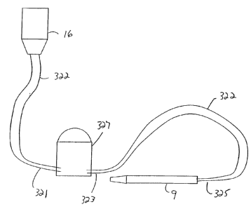
As best seen in FIG. 3, the inventors have discovered a way to increase the
diameter
of tubing without corresponding decrease in handpiece mobility by reducing the
diameter of
tubings 322 at portions 321, 323 and 325 where tubings 322 connect to cassette
327 and
handpiece 9. For example, portions 321, 323 and 325 may have an internal
diameter of
between approximately 0.060 inches and 0.180 inches, with approximately 0.160
inches
being preferred and having an external diameter of between approximately 0.090
inches and
0.200 inches, with approximately 0.190 inches being preferred. Such reduction
in diameter
allows tubings 322 to be more easily connected to conventional cassette 327
and handpiece 9
without modification and decreases the stiffness of portion 325 near handpiece
9. Tubings
322 are of increased interior and exterior diameters along a substantial
portion of the length of
tubings 322, with reduced diameter portions 321, 323 and 325 making up on a
relatively short
portion of the length of tubings 322, for example, between approximately 12.0
inches and
24.0 inches.
This description is given for purposes of illustration and explanation. It
will be
apparent to those skilled in the relevant art that changes and modifications
may be made to
the invention described above without departing from its scope or spirit.