Note: Descriptions are shown in the official language in which they were submitted.
CA 02541542 2006-04-04
WO 2005/047641 PCT/US2004/036513
COMPOSITE RISER WITH INTEGRITY MONITORING
APPARATUS AND METHOD
TECHNICAL FIELD OF THE INVENTION
[0001] The present invention relates to composite structures, apparatus to
monitor the
integrity of composite structures, and a method to monitor changes in
stiffness. The
present invention relates to using displacement, strain and vibration sensors
to monitor
changes in the riser stiffness. In particular, the invention has particular
application to
composite risers used in offshore oil and gas production.
BACKGROUND OF THE INVENTION
[0002] In offshore oil and gas drilling, production, and completion operations
a
platform at the surface of the ocean is connected to the well head on the sea
floor by risers.
A riser is a tubular member through which drilling tools, tubing, and other
components
used in oil and gas exploration pass. The current practice is to make the
risers from steel.
More recently, it has been proposed that the risers be made from composite
materials.
Risers made from a composite material offer the advantage of being lighter in
weight than
steel risers. Thus, composite risers have the advantage of requiring a smaller
surface
platform to support the same length of composite riser than of a steel riser.
[0003] Offshore oil and gas exploration is progressively moving to deeper and
deeper
water. Thus, the weight savings advantage of the composite riser become more
significant
as the water depth in which wells are drilled becomes greater. Some well heads
are on the
sea floor more than 5,000 feet below the surface of the ocean.
[0004] A concern with any deep water oil and gas exploration is maintaining
the
integrity of the riser system. Breaches in the riser system can result in the
escape of
drilling muds, oil and/or gas into the sea.
1
CA 02541542 2006-04-04
WO 2005/047641 PCT/US2004/036513
[0005] The use of composite risers in actual field applications is relatively
new. Thus,
there is little long-term experience concerning the reliability of composite
risers. Clearly,
failure or breach of a riser is to be avoided. The present invention provides
an apparatus
and method for monitoring the integrity of composite risers by monitoring
changes in the
riser stiffness. Monitoring of the stiffness of the risers can allow
identification of
weakened risers and allow their replacement prior to failure. A change in the
stiffness is
monitored using strain sensors or vibration sensors.
[0006] Stiffness is defined as a measure of the amount of deformation per unit
load.
When a riser joints is new, it will have certain stiffness value and therefore
when the joint
is subjected to a certain load, the joint will deform to a certain level,
which can be
measured using displacement gauges of strain sensors. The strain is defined as
the
displacement per unit length of the section over which the displacement is
measured. The
virgin stiffness of a riser joint can be predicted using numerical solutions
and the amount
of strain when the riser joint is subjected to a specific load can also be
predicted using
numerical solutions such as finite element analysis. When the riser is
damaged, the
stiffness will be reduced and the amount of deformation for the same load will
be
increased.
[0007] Stiffness of the composite riser is an important design parameter
because high
stiffness results in high loads when the riser stretches as the platform moves
and low
stiffness is not desirable because it can result in clashing between different
risers. The
axial stiffness of the riser is related to the elastic modulus of the riser,
the cross sectional
area and the length of the riser strength. The length of the riser string is
defined by the
water depth and the cross sectional area is mainly established to ensure that
the riser can
withstand the design loads such as pressure, tension and bending loads. The
elastic
modulus is affected by the fibers used to manufacture the composite riser and
the layout of
the different laminates. While the currently used material, steel, has a fixed
elastic
modulus of 30 million lb/square inch, composite risers can have different
values. The
present invention can be used with composite risers, the elastic axial modulus
of which is
between 5 to 15 million lb/square inch, and preferably a value between 10 and
14 million
2
CA 02541542 2006-04-04
WO 2005/047641 PCT/US2004/036513
lb/square inch. Damage of the composite riser will manifest itself by
reduction of the
stiffness that means the elastic modulus is reduced.
[0008] It is also noted that the composite riser joint will fail when the
strain in the riser
reaches a specific value. This value is in the order of 0.5% for the carbon
fiber composite
risers being considered for offshore applications. An object of the present
invention is
based on monitoring the strain either (1) on a continuous basis to assess the
extent of
damage and also the variation of loading, or (2) by monitoring for the maximum
strain to a
specific value which is lower than the strain at which failure is expected.
This will ensure
sufficient time to remove the damaged joint prior to its failure. In another
aspect the
present invention provides for using the natural frequency of the riser that
influences the
vibration behavior of the riser is a function of the stiffness and mass to
monitor the
integrity of the riser. As the stiffness changes, the natural frequency will
change and thus
the vibration signature will change. Well known technique, but custom curves
are
required to characterize a specific riser because configuration, cross-
section, wall
thickness, material selection, etc. will affect vibration response
characteristics.
Monitoring the changes in the vibration signature, which is commonly done
using
accelerometers, can provide an indication of the level of damage. Because of
the
complexity of the composite structure, theoretical predictions of the
relationship between
level of damage and changes in strains or vibration signature are difficult.
Therefore,
calibration curves need to be developed as part of the qualification program.
This will
involve testing some composite joints to induce damage. In one embodiment of
the
invention, fiber optics are used as the strain sensors and a test method is
provided
demonstrating the qualification of the riser when strain monitoring is used.
SUMMARY OF THE INVENTION
[0009] In one aspect, the present invention relates to a composite structure
adapted for
the measurement of changes in the stiffness of the composite structure. In a
preferred
embodiment, the composite structure is a composite riser having a metal liner
with metal
composite interfaces attached to each end. The riser is covered with one or
more
3
CA 02541542 2006-04-04
WO 2005/047641 PCT/US2004/036513
composite structural members. The riser includes at least one strain gauge
attached to the
riser. Preferably, the riser includes a first strain sensor oriented in a
first orientation and a
second strain sensor oriented in a second orientation. These strain sensors
can be of any
known design; however, in the preferred embodiment the strain sensors are
fiber optic
strain gauges and electromagnetic sensors (steel elements) which are embedded
in the riser
during fabrication.
[0010] The strain gauges can be positioned in areas of interest. Typically,
these areas of
interest will be the areas most likely affected by internal damage to the
composites; for
example, the area where the composite structure and the metal connector
interfaces are
joined. This area is called the metal-composite interface (MCI).
[0011] In another embodiment the present invention relates to monitoring
changes in
the composite riser stiffness using vibration monitors (e.g. accelerometers)
that will allow
determining changes in the natural frequency and mode shape of the composite
structure.
[0012] In another embodiment, the present invention relates to a monitoring
system for
a riser assembly. In this embodiment, a plurality of risers extend from the
well head on
the sea floor to the surface platform. In this embodiment, the strain sensors
and the
vibration monitors located in each riser are connected to a control unit on
the surface
platform. The control unit on the surface platform has a means to generate a
signal to the
individual strain sensor in each riser, to measure the strain and vibration
response in each
riser, and to record the measured strain and natural frequency. Preferably,
the measured
strain and/or natural frequency are recorded together with the time that the
strain and/or
the vibration responses are measured as well as the riser in which the
responses were
measured. Alternatively, the strain and/or vibration responses in only
selected risers can
be monitored.
[0013] In another embodiment of the present invention, a monitoring module is
provided on the individual riser. This obviates the need to connect the risers
to the surface
via a transmission line. The monitoring module has a power source, a processor
unit, a
communication device, and a signal device. The processor unit of the module
has the
4
CA 02541542 2006-04-04
WO 2005/047641 PCT/US2004/036513
capability of initiating the signal unit to send a signal to the sensor on the
riser. If desired,
more than one monitoring unit can be employed. The processor also includes an
interface
or other device to receive the measured data from the sensors, memory to store
the
measured data, and preferably signal processing capability to compare the
measured data
against a predetermined warning value. With a preferred embodiment, the
processor unit
also includes a signal processing capability to determine the ratio between
the measured
strain in either the first or second orientation against the strain measured
in the other
orientation. In yet another embodiment, the processor also includes a means to
compare
the determined ratio against a predetermined value of the ratio set as a
warning limit.
Preferably, the monitoring module also includes a memory or other storage to
store the
measured strain values and/or the ratio of measured strain values.
Additionally, the
moduling unit contains a communication device to output the strain data and/or
the stored
values. The monitor module can also include a capability to initiate an alarm
in the event
the warning limit is exceeded.
[0014] The invention also is a control system for performing the monitoring of
the
strain. The control system components and functions can be integrated at a
single location
or dispersed to multiple locations. The control system can include an input
interface to
input data and commands such as riser identification, alarm limits, commands
to initiate
measurement; a signal means to send and receive measurement signals to the
strain
gauges; a processing capability to receive the measured data and process the
data as
desired; e.g., compare to warning limits, store the data, output the data; and
a
communication device for outputting data in a desired manner.
[0015] In another embodiment, the invention includes a remotely controlled
submersible vehicle. This remotely controlled submersible vehicle includes a
recorder
device. In one aspect, the recorder includes a processor and a link device.
The link device
provides a communication link to the monitoring module. The processor includes
a
mechanism to initiate a download of stored strain measurements data or ratio
data of strain
measurements from the monitoring module, and a way to store the downloaded
data. The
CA 02541542 2006-04-04
WO 2005/047641 PCT/US2004/036513
recorder also includes a way to output these values when the submersible is
recovered at
the surface.
[0016] In another aspect, the recorder unit of the submersible vehicle
includes a device
to generate a signal to the strain gauges in the riser, The recorder includes
a device to
record the measured strain from the sensors in the individual risers. This
embodiment is
especially suited to the use of electromagnetic strain sensors.
[0017] The method of the present invention can include the steps of sending a
signal to
a strain and/or vibration measuring device in operative association with a
composite riser,
recovering the response to the signal, comparing the response to a warning
limit,
computing the ratio of response measured in one orientation to that measured
in another
orientation, comparing the computed ratio to a warning limit, outputting the
data, storing
the data, and initiating an alarm.
BRIEF DESCRIPTION OF THE DRAWINGS
[0018] The present invention will be better understood in light of the
detailed
description when read in conjunction with the drawings. Any drawings in'
detailed
description represent certain embodiments of the invention and are not
intended to be
limiting of the invention. In the drawings: ,-
Figure 1 is a cross-sectional view of a composite riser of the present
invention;
Figure 2 is a cross-sectional view of a composite riser of the present
invention;
Figure 3 is a schematic representation of orientation of separate fiber optic
strain
sensors of the present invention;
Figure 4 is a schematic representation illustrating the use of a single fiber
optic
strain sensor for both axial and hoop measurement;
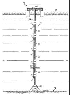
Figure 5 is a riser string and control system of one embodiment of the present
invention;
Figure 6 is a side view of a riser with electromagnetic strain sensors in
another
embodiment of the invention;
6
05-05-2005 CA 02541542 2006-04-05 US0436513
2005 1:02PM HP LASERJET FAX
Docket No. 18326/03402
Figure 7 is an illustration of one embodiment of a monitoring module and
submersible vehicle of the present invention;
Figure 8 is a graph of strain percentage for various test sequences;
Figure 9 is a graph of'the ratio of hoop to axial strain for various test
sequences;
Figure 10 is a schematic illustration of the control system of the present
invention;
Figure 11 is a schematic illustration of alternate embodiments of the
distribution of
control functions;
Figure 12 is a schematic illustration of two embodiments monitor module
attached to
a riser, and a remote vehicle for monitoring the risers; and
Figure 13 is a schematic illustration of a monitoring module.
DETAILED DESCRIPTION
[0019] Figure 1 is a cross-sectional view of one embodiment of a riser of the
present
invention. The figure is not to scale for purposes of illustration. Composite
riser 20 has an
inner liner 22 which defines passageway 24. Liner 22 is preferably of a metal
such as steel,
aluminum or titanium. Adjacent to liner 22 is shear ply 26. Shear ply 26 is a
rubber of
polymeric material. Further, the shear ply is preferably fluid impermeable.
Placed over
shear ply 22 is the main structural layer 28. The main structural layer 28 is
of a composite
material. Covering the outer side of structural layer 28 is a fluid
impermeable layer 30
preferably made of rubber, that is covered by a scuff absorbing layer 32. In
this
embodiment, two fiber optic strain sensors 34 and 36 are embedded in the riser
below the
outer fluid impermeable layer 30. Preferably, they are embedded in the area of
the metal-
composite interface. It will be understood by those skilled in the art that
the specific design
of the riser is not limited to the illustrated design. In apreferred
embodiment, the composite
riser has an elastic axial module of from 5 to 15 million pounds per square
inch, and more
preferably a value from 10 to 14 million pounds per square inch, Risers with
elastic axial
modules within these ranges can be provided by known techniques and methods of
construction using finite analysis to design the composite structure,
7
AMENDED SHEET
Empf
.ze i t : 05/05/2005 20:59 __ . _... -,'846 P .015
CA 02541542 2006-04-04
WO 2005/047641 PCT/US2004/036513
[0020] For the fiber optic strain sensors, the same fiber can contain multiple
sensors.
(See Figure 4.) These sensors are generally formed by machining a grating
(Bragg
grating) in the fiber. When laying the optical fiber, some of the grating will
be positioned
to monitor the axial strains 34 while the others are positioned to monitor the
hoop
strain 36. In order to monitor these sensors, the ends of the fiber containing
the sensors
pass through fluid impermeable layer 30 and the scuff barrier 32 to the
outside for
connection to the monitoring device. Typically the composite riser 20 will be
constructed
by winding the composite fibers over the liner. Normally in such construction
there are
fibers which are positioned longitudinal or substantially parallel to the axis
25 of
passageway 24 and also fibers, usually referred to as hoop fibers, in one or
more directions
running in a direction substantially offset from the axis, such as
circumferential, spiral,
helical, etc. Preferably, the fiber optic strain gauges are embedded in the
riser during
production of the riser. Thus, it is convenient for them to be positioned in
orientations
corresponding to the orientation of longitudinal fibers and to the hoop
fibers. Preferably,
one of the strain gauges is oriented substantially parallel to the axis of the
riser to measure
axial strain. The other strain gauge is preferably positioned and embedded
along the
orientation of one of the hoop fibers. In the hoop orientation the strain
sensor will be
available to measure the hoop strain. Preferably, the orientation of the
strain sensor
embedded in the hoop direction is substantially perpendicular to the axis of
the riser. In a
less desired embodiment, the orientation of the strain sensor embedded in the
hoop
direction is at an angle within 30 degrees of the perpendicular to the axis.
The orientation
of the other strain gauge should be substantially longitudinal and preferably
is parallel or
not more than 20 degrees from being parallel to the axis of the riser. The
preferred
location for the fiber optic strain gauge is in the main structural layer but
they can be
positioned elsewhere if desired.
[00211 Figure 2 is a simplified cross-sectional view of composite riser 20. On
the
interior of the riser is metal liner 22 along axis 25. On each end of the
liner are attached
metal composite interface portions 40 and 42. Metal composite interfaces 40
and 42 are
provided with metal connectors 44 and 46 respectively. In this example,
flanges are
shown, but other commonly used oilfield connectors such as pin and box
threaded joints
8
CA 02541542 2006-04-04
WO 2005/047641 PCT/US2004/036513
can be considered. These metal connectors can contain holes 48 through which
bolts or
other fasteners can be passed to connect two or more risers together. The
layers
surrounding the liner 22 and the metal composite interfaces 40 and 42 are
generally
indicated as 50. The details of the layers have been omitted for purposes of
clarity. In this
illustrated embodiment, two longitudinally oriented strain gauges 34 and 34'
are provided.
These are illustrated as extending some length along the riser axis. The
particular length
and number of these first strain gauges is a matter of choice. Also, if
desired the various
first strain gauges can be installed at different depths within the structural
composite
layers 50.
[0022] Two second strain sensors 36 and 36' are shown in the hoop orientation.
These
strain gauges are helically wrapped about the axis 25 and within the outer
layers 50. Like
the first strain sensors 34, second strain sensors 36 can be positioned at
various depths.
Also, one or more second strain sensors can be employed. As illustrated in
Figure 2,
second strain sensors 36 and 36' are wrapped in a helical fashion or about the
axis. The
preferred orientation for the second strain sensors is along the circumference
of the risers,
i.e. 90 degrees of the axis 25.
[0023] The fiber optic strain gauges are preferably embedded in the structural
layer 28.
The strain gauges are also preferably positioned such that they are adjacent
to the portions
of the riser 20 most likely to be damaged or to fail, which is typically the
metal-composite
interface area.
[0024] Figure 3 illustrates the fiber axial optic sensors 54 and the hoop
sensor 56 that
can be used for measuring the axial strain and the hoop strain. Figure 3 shows
the use of a
separate fiber for each strain sensor. Axial strain sensor 54 has an axial
fiber optic strain
sensor portion 58, a fiber optic tail portion 60 connecting the axial strain
sensor portion 58
to lead 62 for connecting to monitoring equipment. Hoop strain sensor 56 can
have the
same construction as axial strain sensor 54, except that the hoop strain
sensor portion 64 is
positioned substantially perpendicular to the axis 25. Figure 4 illustrates
the use of single
optical fiber 66 having sections, a strain sensor section 67 and a hoop strain
sensor
9
CA 02541542 2006-04-04
WO 2005/047641 PCT/US2004/036513
section 68, to measure both axial and hoop strain. If desired more than two
sensors can be
provided per optical fiber to provide for redundancy as well as temperature
compensation.
[0025] Figure 5 illustrates another embodiment of the present invention.
Figure 5
illustrates riser string 70 composed of a number of individual risers 20. The
top of the
riser string 70 is connected to a surface platform 72 on the surface 74 of the
ocean. The
lower portion of the riser string 70 is connected to the wellhead 76 on the
sea bed floor 78.
In this embodiment, a transmission line 80 extends from the surface platform
72 along the
riser string 70 and is connected to leads 84 and 86 to the first and second
strain gauges in
the separate riser sections 20. In the illustration, each riser 20 has its
strain gauges
connected to the transmission line 80. The transmission line 80 can be
attached to the
outside of the riser string or embedded in the risers 20. However, only a
selected riser
joint 20 can be monitored if desired. In a preferred embodiment, each riser
joint 20 is
monitored.
[0026] Transmission line 80 is connected to controller 82. Signals can be sent
from
controller 82 to the various strain gauges on the various risers 20 and the
measured strain
data on one or more selected strain gauges is returned. Transmission line 80
may be a
single common line for a plurality of risers 20, or may be a bundle of
transmission lines,
one for each riser. Well known electrical addressing techniques may be used in
the case of
a common transmission line 80 for communicating with a selected one of a
plurality of
risers connected to that line. Measured strain can be displayed to the user,
recorded in a
databank, or compared against a preset warning level, which if reached, causes
an alarm
signal, such as a light, sound, etc. to be activated. Preferably, the
controller 82 records the
date, time and measured data for each riser and the identification of the
riser. This
provides a historical record of measured data to be used to improve riser
design, predict
the life cycles, and to identify risers in need of preventative replacement.
[0027] Figure 6 illustrates another embodiment of the present invention. A
transmission
line 80 extending along the length of riser string 70 has certain drawbacks,
including the
difficulty of installation and protection from damage. Thus, in another
embodiment of the
CA 02541542 2006-04-04
WO 2005/047641 PCT/US2004/036513
present invention, a monitoring module 90 is provided. The monitoring module
90 is
provided with a means to attach it to the riser, such as a collar 92 for
mounting on riser 20.
In the illustrated embodiment, collar 92 has a first arm 94 hingially
connected to a second
arm 96 by hinge 98. Arms 94 and 96 at their free ends 100 and 102 are provided
with
holes through which a bolt 104 can pass. In a preferred embodiment, a spring
106 is
provided on the outside of one of the free ends. Spring 106 serves to bias
arms 94 and 96
against the outside of riser 20, to compensate for any decrease in riser
diameter as it is
subjected to increasing pressure the further it is extended into the sea. Of
course other
types of connections are equally suitable such as clamp, fasteners or even
glue. The
module 90 is provided with connectors 108 and 110 to connect to the leads of
first and
second strain sensor. Thus, the strain sensors are connected to a signal
device 111 and
control device module 112. Control device 112 has attached to it output/input
communication device 114 which is described further below. Control device 112
can be a
battery powered computer processor 116.
[0028] Preferably, the processor 116 is programmed to initiate a signal or
prompt the
signal device to send a signal to the first and second strain sensors at a
predetermined time
or on command. The processor may be any type of computer, microcomputer,
microprocessor, or digital or analog signal processor. The strain data from
each sensor in
response of the signal is received and processed by the processor 116. In one
embodiment, the signal received can be compared against a predetermined strain
data
value corresponding to a warning limit. Preferably, the strain data is stored
in a memory
for later download. In a preferred embodiment, the memory is located inside
the
module 90. The processor is also connected to one or more output/input
communication
device 114. The output/input communication device can be in the form of
acoustic
transceiver, a hard connection to the transmission line, optical link or other
means. In one
embodiment, the strain data is stored in module 90 until a submersible vehicle
120 aligns
with the communication device for inputting and outputting stored data from
the control
device 112. The stored strain data can be downloaded to a recorder 126 on the
submersible vehicle 120. The submersible vehicle 120 can then be recovered at
the
surface and the data obtained from the module extracted for use.
11
CA 02541542 2006-04-04
WO 2005/047641 PCT/US2004/036513
[0029] In another embodiment, the control device 112 can also include an
acoustic
generator 127 as a communication device. Strain data values can then be
transmitted
directly to the surface acoustically. Alternatively, strain data values can be
stored until
downloaded to the remote vehicle 120. Preferably, even in the situation where
strain data
values are stored an immediate action is desirable in the event that the
warning limit is
exceeded, in which case an acoustic signal is transmitted to the surface to
activate an
alarm on the surface platform.
[0030] The monitoring module 90 can be provided with a capability or fixture
for
aligning the submersible 120, such as projection 122, to assist in aligning
the
communication terminal 114 of the monitoring module 90 in position to
communicate
with the communication device 124 of the recorder 126 of the submersible 120.
The
submersible vehicle can also have an alignment means such as recesses 129 to
receive
projections 122. The submersible may be of any known design for submersible
vehicle
and preferably is remotely controlled from the surface platform. The
submersible 120 is
equipped with a recorder 126. The recorder 126 can include a control element
to signal
the control device 112 of the monitoring module 90 to download data. In one
embodiment, the submersible is positioned such that the communication means
124 of the
submersible and communication device 114 of the monitoring module 90 are in
communication and strain data is downloaded to the recorder 126 on the
submersible for
later recovery and processing at the surface. One type of self contained
monitoring ,
module system is disclosed in U. S. Patent 4,663,628. Details of the internal
operation of
monitoring module 90 are omitted as the construction and programming of
microprocessor
based data collection and storage systems is well known.
[0031] Alternatively, the submersible can include a control element 130 to
directly
initiate a signal to the strain sensor and then record the response strain
measurement. In
this embodiment, the monitoring module is not required. Instead, the
submersible aligns
with the leads to the fiber optic strain gauges and transmits a strain signal
and records the
response.
12
CA 02541542 2011-03-16
[0032] In another embodiment the strain sensor may be a piezoelectric strain
sensor.
Currently, these have the disadvantage that with the current technology they
are rather
bulky and are not as conveniently incorporated into the composite riser as are
the fiber
optic strain sensors. The piezoelectric strain sensors are connected to leads
and the
operation is like that as described in relation to the fiber optic strain
sensors. The
disadvantages of piezoelectric sensors may change over time vending this type
of sensor
more desirable for use in implementations employing the present invention.
[0033] In yet another embodiment of the invention, the strain sensors are
magnetic.
Magnetic strain measurements have the advantage that a power supply mounted in
a
monitoring module is not needed. As illustrated in Figure 7, a first magnetic
strain
sensor 131 and a second magnetic strain sensor 132 are strips of metal adhered
or
embedded into a composite riser. A third magnetic strain sensor 133 and a
fourth
magnetic strain sensor 134 are also strips of metal adhered or embedded into
the
composite riser. The magnetic gauge can be a wire of magnetic material bonded
within
the structure, or it can be a strip of magnetic material with a reduced cross-
sectional area
in the midportion of the strip which increases the sensitivity of the gauge.
These
magnetic gauges are passive in the sense that no direct connection to a
circuit is
required, and magnetic detection equipment is employed in conjunction with
gauge. This
detection equipment generates a magnetic field and measures the difference in
the fluid
causeD by the gauge. The detection equipment can be contained in the
submersible
vehicle. Strain is measured by measuring the change in the magnetic field
associated
with changes in the magnetic sensor caused by strain. Thus, these magnetic
strips can be
adhered to the composite riser and the magnetic field monitored and recorded
by a
remote vehicle. Magnetic gauges may also be used with a monitoring module to
simplify
the attachment of the monitoring module and to obviate the need for electrical
or optical
connections to the module.
[0034] In yet another embodiment, the strain gauge can be a resistance gauge
or an
acoustic gauge. An acoustic strain gauge is shown in U.S. Patent 5,675,089
entitled
"Passive Strain Gauge".
13
CA 02541542 2006-04-04
WO 2005/047641 PCT/US2004/036513
[0035] In yet another embodiment, accelerometers are used to measure the
vibration
response for determining strain data. The vibration signal can be analyzed by
any number
of means including frequency transform using fast Fourier transform
algorithmic analysis
to detect variations in natural frequency and shift in phase angle.
Testing for Setting Warning Values
[0036] For each composite riser design, testing of the riser should be
performed and
measurements of changes in axial displacement, axial and hoop strains, and
vibration
signature during pressure testing recorded. This testing allows one to
empirically
determine values to be employed as warning limits in the monitoring of
integrity in the
operational environment. Preferably, the strain sensors are installed in the
test riser at
selected locations during fabrication. The accelerometers are mounted on the
riser joint
after fabrication. This test riser is then subjected to a sequence of
increasingly severe
loads that are intended to create damage in the test specimen. An example of
such testing
protocol is described below and is summarized in Table 1.
TABLE 1
Load Sequence Load Case Comment
1 Pressure to 427.5 bar (6200 psi) and hold for 5 min.
2 Pressure to 427.5 bar and hold for 15 min.
3 T 1) Pressure to 315 bar (4500 psi) and hold for 5 min. Baseline
measurement.
4 T 2) Pressure to 315 bar.
Axial load to 2060 lcN without internal pressure.
6 Axial load to 2060 kN without internal pressure.
7 Axial load to 2060 kN with 30 bar internal pressure.
8 Axial load to 2060 kN with 30 bar internal pressure.
9 (FPT 3) Pressure to 315 bar.
Axial load 2550 kN with 30 bar internal pressure and First extreme axial load
hold at max. load for 5 min. sequence.
11 Cyclic axial load between 2060 kN and 2550 kN for First cyclic load
sequence.
101 cycles 0.1 Hz, with 30 bar internal pressure.
12 (FPT 4) Pressure to 315 bar.
13 Axial load 4500 kN with 30 bar internal pressure.
14 Cyclic axial load between 3500 kN and 4500 kN for
101 cycles 0.1 Hz, with 30 bar internal pressure.
(FPT 5) Pressure to 315 bar.
16 Axial load 5000 kN with 30 bar internal pressure.
17 Cyclic axial load between 4000 kN and 5000 kN for
109 cycles 0.1 Hz, with 30 bar internal pressure.
18 PT 6) Pressure to 315 bar.
14
CA 02541542 2006-04-04
WO 2005/047641 PCT/US2004/036513
TABLE 1
Load Sequence Load Case Comment
19 Axial load 5800 kN with 30 bar internal pressure.
20 Cyclic axial load between 4800 kN and 5800 kN for 50
cycles 0.1 Hz, with 30 bar internal pressure.
21 Cyclic axial load between 4700 kN and 5900 kN for 20
cycles 0.1 Hz, with 30 bar internal pressure.
22 Cyclic axial load between 4600 kN and 6000 kN for 20 Max axial load higher
than
cycles 0.1 Hz, with 30 bar internal pressure. predicted failure load of
5925 kN (1330 ki s).
23 Cyclic axial load between 4400 kN and 6200 kN for 20
cycles 0.1 Hz, with 30 bar internal pressure.
24 PT 7) Pressure to 315 bar.
25 Axial load 6500 kN with 30 bar internal pressure. Failure after 4:20 min at
6500 kN steady load.
26 PT 8) Pressure to 315 bar.
27 Axial load 2060 kN with 30 bar internal pressure. Same as 7 and S.
[0037] Figure 8 shows a graph of the sequence of loading tests to cause
progressive
damage to the composite riser. The x axis of Figure 8 is the load sequence
number for
Table 1, and the LHS y axis is pressure in bars and the RHS y axis is the
axial load in kN.
In an actual test performed by the inventors, the test specimen failed at load
sequence 25 at
an axial load 6,500 kN. Failure was detected by a loud bang and by a drop in
the load
from 6,500 kN to 5,500 kN. On visual inspection the riser had numerous small
cracks on
the outer surface at the middle of the riser and towards one end. The riser
joint was cut
open and it was found that the composite had delaminated between the two ends
with
visible cracks in the matrix in the hoop layers in the trap locks. Despite
this amount of
damage the riser integrity remained mostly intact. This was demonstrated by
the
subsequent ability of the specimen to withstand load sequences 26 and 27 that
includes a
pressure test of 315 bar and axial test 2,060 kN.
[0038] During the testing, strain was monitored using both fiber optic sensors
and strain
gauges. In Figure 9, the x axis in the FPT sequence number from Table 1, the
measured
axial strain during eight pressure cycles is shown in Figure 9. Figure 9 shows
the changes
in the axial strain when the joint is loaded and also the residual axial and
hoop strains at
zero loads. These results indicate the changes in the strains as a measure of
damage.
CA 02541542 2006-04-04
WO 2005/047641 PCT/US2004/036513
[0039] The measured strain clearly shows that the strain pattern changed over
the test
duration. Importantly, it was discovered that the ratio of the hoop strain to
axial strain
serves as an excellent indicator of progressive damage. Figure 10 presents the
changes in
the strain ratio after different FPTs (x axis FPT sequence number from Table
1) for fiber
optic sensors embedded in the composite joint. Figure 9 shows the percent
strain
corresponding to sequences of the testing. As shown in Figure 9, an indication
of failure
occurred when the longitudinal (axial) strain increased by about 100% (from
0.115 at the
reference FPT to 0.2% for the FPT prior when the failure was observed, see
squence
number 7). Even when the strain increased by 100%, the riser design pressure
and axial
load capacity was not compromised indicating that the riser still had
sufficient capacity to
be retrieved without compromising the safety of the riser. As a safety
measure, a realistic
criterion may be preferably set at a change in the strain of 50% for removal
of the joint
from service or other predetermined value. One benefit' of the present
invention is that
historical data can be used to adjust the warning value based on in-service
experience.
Alternatively, the residual axial or hoop strains at zero loads can also be
used as an
indicator of damage development as shown in Figure 9. Values increase after
the severe
loading cycles.
[0040] The measured strain clearly showed that the strain pattern changed over
the test
duration. Detailed analysis of the changes in the strain pattern demonstrate
the absolute
value of the strain under load, the residual strain under zetro load and the
ratio of the hoop
strain to axial strain thus serve as an excellent indicator of progressive
damage.
[0041] The changes in the axial strain under constant load, as the joint is
progressively
damaged, means that the stiffness is the joint is decreasing, which can also
be measured
using vibration monitoring techniques. In another aspect the present invention
provides
for using the natural frequency of the riser that influences the vibration
behavior of the
riser is a function of the stiffness and mass to monitor the integrity of the
riser. As the
stiffness changes, the natural frequency will change and thus the vibration
signature will
change. Well known technique, but custom curves are required to characterize a
specific
riser because configuration, cross-section, wall thickness, material
selection, etc. will
16
CA 02541542 2006-04-04
WO 2005/047641 PCT/US2004/036513
affect vibration response characteristics. Monitoring the changes in the
vibration
signature, which is commonly done using accelerometers, can provide an
indication of the
level of damage. Because of the complexity of the composite structure,
theoretical
predictions of the relationship between level of damage and changes in strains
or vibration
signature are difficult. Therefore, calibration curves need to be developed as
part of the
qualification program.
[0042] While warning limits may be empirically determined as described above,
warning limits may also be analytically determined based on predated behavior
of the
structure so long as adequate models are available. What is pertinent for the
current
disclosure is not the details of well known modeling techniques, but, instead,
how warning
limits are utilized.
Control System
[0043] The control and monitoring functions can be consolidated at the
controller 82 on
the surface platform 72, or divided among the monitoring modules 90 on the
composite
risers 20 and the recorder 126 of the submersible vehicle 120. The control
system and
method will be discussed first as an overall system and method in reference to
Figure 11.
It is understood that the specific components and functions can be implemented
in
different manners by different devices at different locations in the system.
The functions
can be performed by a computer, microcomputer or microcomputer based system
programmed to perform the functions operating in conjunction with peripheral
devices.
Alternatively, some functions can be conducted by a circuit or device having
specific
functionality rather than a programmed computer.
[0044] In a preferred embodiment, an input device, block 140, such as
communications
port or interface is provided to input basic information into the processor.
This
information can include, an identification assigned to each individual riser
to be
monitored, clock settings, timing sequence for testing, and warning limits.
The strain
measurement sequence can be initiated on command inputted by the operator, or
automatically based on a timing program or by input from sensors triggered by
certain
17
CA 02541542 2011-03-16
events, such as environmental conditions indicative of severe weather which
could
produce severe strain on the riser string. This function can be performed by a
means to
initiate measurement such as a keyboard, timing program, or inputted sensor
signal,
block 142.
[0045] The system includes a strain measurement signal generator and receiver
of the
return measured strain value, block 144. This can be performed by known strain
measuring equipment for the type of gauge being employed. The measured strain
in each
orientation is inputted into the control system. The control unit preferably
includes a
visual output device, block 146, such as a display screen, printout, or other
means to allow
the operator to view the results. In a preferred embodiment, the processor
also includes a
capability to correlate the measured strain data, block 150, with the time at
which the
measurement was taken and a means for storage of that information, block 148
and a means
to output, block 154, the information. Additionally, it is preferred that the
control system include a
capability for calculating the ratio of strain data measured, block 150, in
either the first or second direction
against the strain measured in the other orientation. The ratio value is
preferably stored together with
the time that the measurements used to compute the ratio were taken. In a
preferred
embodiment, an input means such as a keyboard or a ROM chip is provided for
input of
the predetermined warning value for strain data in one or more of the first
orientation,
second orientation, and/or strain ratio indicative of a strain threshold on
the riser predictive
of damage or failure. The controlled processor preferably includes a means
such as
program code to compare the measured strain against the predetermined warning
value,
block 150.
[0046] The system preferably includes an alarm generating means such as a
computer
program which initiates an alarm 152 perceptible to the operator such as a
visual display,
sound, or other indicator. In the embodiment where a monitoring module is
attached to
the individual risers, this alarm means can include an acoustic signal
generator in the
monitoring module which sends acoustic signals to a receiver connected to the
controller
on the surface platform. The method of the present invention in a preferred
embodiment
involves the steps of inputting to the processor base data, which preferably
includes
18
CA 02541542 2006-04-04
WO 2005/047641 PCT/US2004/036513
warning limits, initiating strain measurement, conducting strain measurement,
collecting
strain data, and outputting the strain data. Preferably, the method also
includes comparing
the strain data against predetermined warning limits, outputting an alarm
signal if the
warning limit is exceeded. Additionally, the method also includes storing of
the strain
data.
[0047] When the control system includes monitoring modules on the individual
risers, a
submersible vehicle may be beneficially employed. Use of a UAV is desirable as
it
eliminates a need for a transmission line from each monitor to the surface.
Also, the
submersible is preferred in order to conserve power in the monitoring module's
power
system. It is also preferred that the control system include a storage device
to store data
and allow for a database of the measured strain for each riser and details of
the riser
construction. Suitable types of storage devices are well known and include
semiconductor
memory, RAM FLASH, etc. An output device 124 is provided to output, in
electronic,
optic, magnetic, or other form this information which can then be either
transferred to
another computer processor, or visually displayed. Retention of a historical
record can be
desirably used to improve riser design and to perfect and refine appropriate
warning limits.
[0048] The monitoring system can be constructed in many different manners, and
in a
preferred embodiment, one or more monitoring modules 160 are attached to each
riser 20
or selected risers within the string as illustrated schematically in Figure
12. The
monitoring module 160 contains a central processor unit 162, a communications
device 164 to provide communication with the remote controlled submersible
vehicle or to
provide acoustic communication, optical communication or other communication
with the
surface platform. Processor unit 162 may be any suitable type of computer,
computer
module, microcomputer, microprocessor, or digital signal processor. The module
further
includes a power supply 166 such as a battery to power the unit, a signal
device 168 and a
memory device 170. The signal device 168 transmits and receives signals to and
from the
strain sensors.
19
CA 02541542 2006-04-04
WO 2005/047641 PCT/US2004/036513
[0049] The central processing unit 162 can be programmed in many different
fashions
to satisfy the needs of the user. Preferably, the unit has stored in memory an
identification
of the riser to which it is attached. This identification is used to correlate
the output data
of the strain or vibration sensors with the particular riser. The processor is
programmed to
receive command signals and/or a stored timing routine. The processor
generates a signal
to the signal device which initiates the delivery of a signal to the strain
sensor, the return
signal is received by the signaling device and the strain value is compared to
the warning
limit. Similarly, the strain measured in the second orientation is compared
against
warning limits. The ratio of the strain measured in the first orientation with
that measured
in the second orientation within a predetermined time is computed and compared
against
the stored warning limit. If the warning limit is exceeded, the processor can
generate a
command to the communication device to send an alarm signal to the surface. It
is not
necessary to make the comparison to the warning limits. Preferably, all
measurements
made are then stored in the memory device 170. Preferably, the data stored
includes the
time of the measurement, strain measured in the first direction, strain
measured in the
second direction, and a ratio of the strain measured in the two orientations.
The processor
is further programmed to download the stored data upon receipt of a command
from the
recorder unit 180 in the submersible vehicle or from the surface controller.
The recorder
unit 180 contains a processor 182, a communication device 184, and a memory
device 186. The recorder can be powered by the power supply of the submersible
vehicle.
The submersible vehicle can also include lights and video equipment commonly
used for
underwater visual inspection. The recorder 180 can input into monitor module
160 new
base information updates such as a change in the warning limit and accept
downloads of
strain data from the monitoring module 150. This arrangement can be repeated
for each
riser.
[0050] Figure 12 shows another embodiment in the lower half of the figure. One
or
more alignment devices 190 is preferably provided adjacent to the strain
sensors. The use
of an alignment device is useful when the strain sensors are magnetic sensors.
The
alignment device allows for the consistent positioning of submersible vehicle
with the
embedded magnet sensor. The submersible vehicle aligns with the strain sensors
and
CA 02541542 2011-03-16
takes measurements. In this embodiment, the recorder 180 includes a strain
signal
device 188, for example, a magnetic field generator and sensor to measure
strain in
embedded magnetic strain sensors (131, 132; see Figure 7). Preferably, the
downloaded
data includes the stored strain measurement data as well as identification of
the riser. The
data stored in the memory of the recorder is recovered when the vehicle is
brought to the
surface. The various steps of the measuring and the functioning of the system
can be
performed either by the surface controller, by the modules, or by the recorder
in the
submersible vehicle if employed.
[0051] Further details of the internal operation of the monitoring modules is
omitted for
simplicity because the electronic and microcomputer based systems for
recording and
storing data are well known in the art. For example see U.S. Patent No.
4,663,628.
Accordingly, what is pertinent to the current disclosure is the functions
performed by the
module, how the modules are accessed and/or interconnected and where and how
the
modules are placed. Similarly, exterior structural characteristics of the
modules is not
discussed as this is well known. What is pertinent to this disclosure is that
the modules
must be rugged and be able to withstand the harsh environment and pressure to
which they
will be subject without an unacceptable rate of loss of stored data.
[0052] Figure 13 is a schematic illustration of monitoring system. Processor
200 is
provided, and is powered by a power source 202, for example a battery, the
processor has
ROM and RAM memory 204, and can be connected to a storage device 206. The
processor is connected to at least one signal generator 208, and strain gauge
interface 210.
Preferably the processor 200 has a connector interface 212, and a
communication
device 214. The communication device inputs from and outputs to receiver 216
data. A
command interface 218 can be provided for receiver commands from a command
input
device 218.
[0053] While the present invention has been described in relation to various
embodiments, the invention is not limited to the illustrated embodiments.
21