Note: Descriptions are shown in the official language in which they were submitted.
CA 02541806 2006-03-07
WO 2005/023537 PCT/EP2003/010129
Cut-resistant composite
Field of the invention
The present invention relates to the field of cut-resistant composites and cut-
resistant
fabrics. In a first aspect, the present invention relates to a cut-resistant
composite. In another
aspect, the present invention relates to a cut-warning composite. In yet
another aspect the
present invention relates to a method for preventing vandalism on a composite.
In another
aspect, the invention relates to the use of a composite according to the
present invention as
an anti-vandalism composite.
1o
Background of the invention
In order to prevent thefts, recently researches have been done to obtain cut
resistant
materials and constructions. This has already a lot of applications,
especially in
thermoharding materials. There are also known types of reinforcements for
thermoplastic
materials as e.g. a knitted "loop" fabric based on a knitted metal loop
reinforcement. Also a
woven tarpaulin reinforcement is already known comprising woven and knitted
steel
constructions. These last constructions have as major difficulty, i.e. the
stiffness and the
weight. The first "loop" knit construction has as major difficulty when it is
used as "anti-
hooligan" fabric in seats of trains, trams, busses, it may, upon damage pierce
and stick
2o through the fabric. So even if it helps a lot to improve cut resistance in
the fabric, the seat can
no more be used as the metal will pinch through the skin of the user as well.
A major difficulty of the existing fabrics and/or composites is that the
fabric reinforcing
elements, e.g. yarns, fibers, cables, once embedded and thus connected to a
matrix, are
acting as individual elements during cutting or perforation. The reinforcing
elements are cut
through one after the other. For example, when a first yarn is cut, cutting
starts at a second
yarn. Once the second yarn is cut through, cutting continues at a third
reinforcement yarn,
and so on. As a consequence, the reinforcement elements which act as
individual elements
can be more easily cut through and will not provide sufficient cutting
resistance to the fabric
or composite.
3o There remains a great need in the art for composites and fabrics having
improved
cutting resistance.
It is therefore an object of the present invention to provide an improved cut-
resistant
composite.
CONFIRMATION COPY
CA 02541806 2006-03-07
WO 2005/023537 PCT/EP2003/010129
2
It is in particular an object of the present invention to provide a composite,
which has
higher cutting resistance than currently available composites.
It is also an object of the present invention to provide a cut-warning
composite.
In addition, another aim of the present invention is to provide a method for
preventing
vandalism on a composite. In particular, it is an object of the present
invention to provide a
method for activating an alarm signal when a composite is being cut through.
Summary of the invention
In a first aspect, the present invention provides a composite having improved
cutting
to resistance. The present invention provides in a composite comprising:
- a matrix, provided on at least one side with a fabric, said fabric,
comprising at least
two layers andlor at least two directions of individual elements of which at
least one
individual element is reinforced and which elements are interconnected by
chemicals,
plastics, rubbers and/or by connection elements which connection is weaker
than the
reinforced element, and
- at least one insulating layer interposed between said matrix and said
fabric.
By providing an insulating layer between the fabric and the matrix, the
present
invention provides a composite and/or a fabric wherein the reinforcement
elements in the
fabric and/or composite will not act as individual elements but will act as a
"group" or a "set"
of elements. A major advantage of the reinforcement yarns or elements to act
as a set of
elements is that different elements are able to simultaneously undergo some
displacement,
when acting upon by a cutting element. As a consequence, individual elements
will less
easily be cut through, and cutting resistance of the fabric will be greatly
improved. The
present invention thus provides a composite having maximal cutting resistance,
by enabling
the anti-cutting or anti-vandalism reinforcement elements to act as free as
possible, i.e. by
creating "bundles" or "groups" of individual elements before a single element
gets cut
through.
In addition, in a preferred embodiment, the present invention also provides a
composite
whereby said fabric comprises free spaces between the individual elements, and
whereby
3o preferably the volume of said free spaces in said fabric is greater than
the volume of the
individual elements.
The presence of free spaces or cavities between the individual elements of the
fabric
considerably improves the ability of the individual elements acting as a group
or bundle of
CA 02541806 2006-03-07
WO 2005/023537 PCT/EP2003/010129
3
individual elements to undergo some movement or displacement, when acting upon
by a
cutting element and thus again greatly improves the cutting resistance of the
composite.
In a second aspect, the present invention provides a cut-warning composite.
The
invention provides a composite capable of activating an alarm signal when
subjected to acts
of vandalism, such as e.g. being cut or pierced through.
In an embodiment, the composite is provided with at least two insulating
layers
whereby at least one layer is provided on one side of said fabric, and at
least one other layer
is provided on the other side of said fabric. In a particularly preferred
embodiment, at least
one insulating layer is able to act as a positive electrical conductor, and at
least one other
to insulating layer is able to act as a negative or neutral electrical
conductor, such that
connection between said positive with said negative or neutral electrical
conductor is capable
of activating an alarm signal. As soon as an electrical conducting object such
as the steel of a
knife, cutter, bore, scraper, or similar object, penetrates through the
material, the two
insulating layers are brought into contact with each other, a contact is made
in the electrical
circuit, and an alarm system will be activated.
In another embodiment, the invention provides a composite, which comprises a
cut-
warning fabric. In accordance with the present invention, the alarm system may
be either
activated upon a) interruption / cutting off or closure of an electrical
circuit provided in the
fabric, or b) providing a contact between a positive and a neutral or negative
electrical circuit
2o provided in the fabric. One possibility is that the layer of reinforcement
elements is acting as a
circuit. As soon as one end is cut, the electrical circuit is broken and an
alarm goes on. Such
type of composite is particularly suitable for preventing acts of vandalism
performed with non-
conductive, e.g. ceramic cutting elements. Another possibility is that one
layer of
reinforcement elements is acting as a positive conductor and another layer is
acting as a
negative or neutral conductor, such that connection between both layers
induces an alarm
signal. Such type of composite is particularly suitable for preventing acts of
vandalism
performed with conductive cutting elements.
In a third aspect, the present invention provides a method for preventing
vandalism on
3o a composite by activating an alarm signal when the composite is subjected
to acts of
vandalism, e.g. cut through. The alarm system may be activated when someone
tries to cut
or cuts through the composite. In accordance with the present invention, the
alarm system
may be activated upon providing a contact between a positive and a neutral or
negative
CA 02541806 2006-03-07
WO 2005/023537 PCT/EP2003/010129
4
electrical circuit (i.e. the insulating layers or the reinforcement elements)
provided in the
composite according to the present invention.
In one embodiment, said method for preventing vandalism on a composite
comprises
a. providing said composite with a fabric and at least two insulating layers,
whereby at least one layer is provided on one side of said fabric and another
layer is provided on the other side of said fabric, and whereby at least one
of
said insulating layers is able to act as a positive electrical conductor, and
whereby at least one other insulating layer is able to act as a negative or
neutral electrical conductor, and
l0 b. activating an alarm signal when connection between said positive with
said
negative or neutral electrical conductor is made.
In another embodiment, the invention provides a method for preventing
vandalism on
a composite by providing said composite with cut-warning fabric. One
possibility is that the
layer of reinforcement elements in the fabric is acting as a circuit. Another
possibility is that
one layer of reinforcement elements in the fabric is acting as a positive
conductor and
another layer is acting as a negative or neutral conductor. As soon as one
individual element
in the circuit is cut through in the fabric or as soon as a contact is made by
a cutter, knife or
other cutting element, the alarm goes off.
2o The cut-resistant and cut-warning composites or any combinations thereof
according
to the invention are particularly useful as anti-vandalism composites. Those
skilled in the art
will immediate recognize the many possibilities for end uses of the present
invention from the
detailed description and accompanying drawings provided below.
CA 02541806 2006-03-07
WO 2005/023537 PCT/EP2003/010129
Detailed description of the figures
Figures 1-9 represent different embodiments of composites according to the
present
invention.
Fig. 10 to 19 represent different embodiments of fabrics comprised in a
composite
5 according to the present invention.
Fig. 20 shows another preferred embodiment of a fabric comprised in a
composite
according to the present invention.
Fig. 21 represents another embodiment of a fabric comprised in a composite
according to the present invention having two layers of non-woven individual
elements.
l0 Fig. 22 shows another embodiment of a fabric comprised in a composite
according to
the present invention having layers of insulated individual elements.
Fig. 23 shows yet another embodiment of a fabric comprised in a composite
according to the present invention having insulated individual elements and
comprising a
metal wire per layer of individual elements.
Fig. 24 shows another embodiment of a fabric comprised in a composite
according to
the present invention having layers of insulated individual elements.
Fig. 25 shows yet another embodiment of a fabric comprised in a composite
according to the present invention having insulated individual elements and
comprising a
metal wire per layer of individual elements.
2o Fig. 26 schematically represents the induction of an alarm system in a
fabric
comprised in a composite according to the invention, when a canvas is being
cut with a knife.
The fabric as represented consists of at least two conductive layers, which
are separated in
relation to each other by insulating material.
Fig. 27 shows the use of a canvas on a truck. The canvas is partly or wholly
made of
a composite and/or fabric suitable for activating an alarm system according to
the invention.
The represented composite and/or fabric is provided with a sensor capable of
detecting a
contact made in an electrical circuit in the composite or fabric or cutting
off or closure of an
electrical circuit provided in the fabric. Such detection is transmitted
either directly or
indirectly, e.g. via a satellite system, to a control unit capable of which
subsequently releases
3o an alarm signal.
CA 02541806 2006-03-07
WO 2005/023537 PCT/EP2003/010129
6
Detailed description of the invention
The present invention provides in a first embodiment, a composite that
comprises a
matrix, provided on at least one side of a fabric, a fabric, and at least one
insulating layer
interposed between said matrix and said fabric.
The insulating layer is provided in the composite such that said fabric is at
most only
partly connected to said matrix. The term "at most only partly connected" as
used herein
refers to the fact that the anti-cutting reinforcement elements in the fabric
are either not
connected to the matrix, or only partly connected to the matrix.
By providing an insulating layer between the fabric and the matrix, the
present
l0 invention provides a composite wherein the fabric is either only partly or
even entirely
insulated from the matrix. Such arrangement has several advantages. In first
instance, the
fabric has one additional degree of freedom, is able to move independently
from the matrix
and is therefore more flexible. Furthermore, since the matrix is not, or only
partly connected
to the matrix, the individual elements in the fabric, e.g. yarns, fibers,
etc.., are not or only
partly connected to the matrix. The individual elements are therefore partly
or even
completely free to move, independently from the matrix, when a cutting element
is brought
into the fabric. This ability of the individual elements in the fabric to
undergo movements and
displacements independently of the matrix will considerably improve the
cutting resistance of
the fabric and thus also the cutting resistance of the composite. It allows
the individual
2o elements to act as a set of elements, and not as individual elements, which
are easily cut
through as indicated above.
Preferably, the fabric comprises said fabric, comprising at least two layers
and/or at
least two directions of individual elements of which at least one individual
element is
reinforced and which elements are interconnected by chemicals, plastics,
rubbers and/or by
connection elements which connection is weaker than the reinforced element.
However, other
types of fabrics can be used in the composite according to the invention, as
will be explained
into more detail below.
In another embodiment the invention relates to a cut-resistant composite
comprising:
- a matrix, provided on at least one side with a fabric, said fabric
comprising at least two
individual layers of reinforcement elements whereby in each of said individual
layers
CA 02541806 2006-03-07
WO 2005/023537 PCT/EP2003/010129
7
all reinforcement elements are provided in only one, same direction, said
individual
layers being interconnected or deposited onto each other, and
- at least one insulating layer interposed between said matrix and said
fabric.
In an example, the fabric may consist of two, three, four or even more
individual layers of
reinforcement elements. In particular, in each of these individual layers all
reinforcement
elements in the layer have only one, same direction. Such individual layers of
"single-
directed" reinforcement elements can be superimposed onto each other.
Alternatively, an
insulating layer, e.g. a non woven or a foam layer, can additionally be
provided between two
individual layers of single-directed reinforcement elements. The different
individual layers of
to "single-directed" reinforcement elements can be arranged under a certain
angle with respect
to each other. Said angle preferably differs from 90° and is preferably
comprised between 1
and 89 degrees, and for example 10, 20, 30, 40, 50, 60, 70 or 80 degrees.
In another embodiment, the composite according to the invention comprises at
least
two insulating layers whereby at least one layer is provided on one side of
said fabric, and at
least one other layer is provided on the other side of said fabric. In another
embodiment, the
composite according to the invention further comprises at least one insulating
layer, whereby
said layer is provided between two layers and/or two directions of individual
elements of said
fabric.
In another embodiment, the individual elements in the fabric can also be
interwoven
as long as this weaving, stitching, suing, or whatever textile construction
allows sufficient
freedom to the reinforcement yarns. For example a woven fabric 2/2 or even
better 3/3 or 4/4
binding will give enough freedom to the fabric when the fabric is not embedded
in the matrix.
The invention further relates to a composite wherein the reinforcement
elements in the
fabric are interconnected and/or connected to the insulating layer. It is
important to note that
in such type of connection the connection force between interconnected
reinforcement
elements or between reinforcement elements and the insulating layer, is
preferably lower
3o than the force imposed by a cutting element on the reinforcement elements,
when said
cutting element is forced through the fabric.
As mentioned above, the reinforcement elements in the fabric are not
interwoven but
have only an indirect connection created by chemicals, plastics, rubbers or by
connection
CA 02541806 2006-03-07
WO 2005/023537 PCT/EP2003/010129
8
elements which are weaker than the reinforced element. Preferably, the
insulating layer
allows the penetration of stitching and/or knitting andlor tufting needles or
combinations
thereof so that the reinforcement elements can be connected, e.g. by
stitching, knitting, etc..
to each other. The reinforcement elements can also be interconnected by means
of binding
techniques including but not limited to bonding, gluing, or vulcanization or
any mixtures
thereof.
In another embodiment, the reinforcement elements in the fabric are connected
with
the insulating layer. Such connection is preferably created by chemicals,
plastics, rubbers or
by connection elements, such that the connection between said elements and
said layer is
to weaker than the reinforcement element. It will be clear from the present
description that the
insulating material can also be connected to the reinforcement elements by
means of binding
techniques including but not limited to bonding, gluing, or vulcanization or
any mixtures
thereof. The reinforcement elements can also be connected to the insulating
layer by means
of plastics, rubber, metal coating or connection, melting, intermingling or
other casting and/or
is any combinations thereof.
In a particularly preferred embodiment, the connection, i.e. stitching,
gluing, bonding,
vulcanization or other type of connection, as those mentioned above, is weaker
than the
reinforced element. The connection force between interconnected reinforcement
elements or
between reinforcement elements and the insulating layer, being an adhesive
force, a binding
2o strength, an intermingling strength or other force, is preferably lower
than the force applied by
a cutter, knife or other cutting element on the reinforcement elements so that
this connection
breaks before one reinforcement end is being cut through. In an example, the
reinforcement
elements are stitched, tufted or knitted. The strength of the connection
created by these
stitching, tufting or knitting yarns, acting as binders, is preferably lower
than the force of a
25 knife or cutting element on the reinforcement elements, so that this
connection will break
before the reinforcement elements will be cut through, thereby releasing the
reinforcement
elements from their fixed place in the fabric.
The above-described type of connection thus enables the reinforcement yarns or
elements to act as a "group" or as a "set" of elements, e.g. yarns and not as
individual
30 elements, which improves cutting resistance, as explained above.
In a preferred embodiment, the composite material is cut resistant to a force
of more
than 500 Newton. In another embodiment, the connection elements of the
reinforcement have
a connection force of e.g. 300cNewtom / unit.
CA 02541806 2006-03-07
WO 2005/023537 PCT/EP2003/010129
9
In another embodiment, the present invention provides a composite whereby free
spaces are provided between the individual elements of the fabric. Between the
individual
elements, e.g. yarns, threads, free or open spaces are provided. In
particular, the invention
provides a composite whereby the fabric comprises free spaces between the
individual
elements, and whereby preferably the volume of said free spaces in said fabric
is greater
than the volume of the individual elements. In a preferred embodiment, the
volume of the free
spaces in said fabric is comprised between 3% and 99%, preferably is more than
25%, and
more preferably more than 50% of the total volume of said fabric. In an
example, a volume of
to free space of 50% preferably enables sufficient displacement of the
individual element.
In another preferred embodiment, present invention provides a composite
whereby
the free spaces are filled up with material selected from the group comprising
but not limited
to foam materials or elastic materials. The free spaces can be filled up with
material such as
foam material or foam, having on their own at least 3% and preferably at least
10% non filled
spaces. The free spaces may also be filled up with an elastic material, e.g.
selected from the
group comprising but not limited to polyurethane, rubber, silicone, non-
saturated polyester
which have an elongation under load which is preferably higher than the
reinforcement
element under the same load.
In an example, if a filler such as PP foam is used with a specific weight of
0.90g/cm3,
we could look for a weight of 80 kglm3. This would provide a total free space
in % of 100X
(900 kg - 80kg)/900kg = 91 %.
In another embodiment, the invention relates to a composite wherein the
individual
elements in the fabric consist of single ends. The term "single ends" refers
to the fact that
the individual elements of the fabric, being yarns, fibers, etc... are not
twisted or cabled, but
consist of single yarns, fibers, etc.... The fabric in the composite according
to the invention
thus essentially consists of a set of single individual elements. The
advantages of using
single yarns or single ends versus twisted or folded and cabled yarns is that
single ends have
a lower gauge and weight, that they are more flexible and lighter, and that
they provide lower
3o costs/kg and lower even more lower costs/surface units.
In a further preferred embodiment, the matrix comprised in a composite
according to
the present invention comprises thermoplastics and/or thermosets. The term
"thermoplastics"
CA 02541806 2006-03-07
WO 2005/023537 PCT/EP2003/010129
as used herein refers to materials that can be made soft by the application of
heat and
harden upon cooling, The term "thermosets" refers to materials that can no
more plastify after
setting and/or vulcanization and/or polymerization.
Examples of suitable thermoplastics and/or thermosets for use as matrix
material
5 comprise but are not limited to silicone, a metal foil, damped or sputtered
metal foil, rubber, a
polymer selected from the group comprising, PVC, polyester, polypropylene,
polyamide,
polyethylene, ethylene/butene copolymers (PEB), poly ethylene terephtalate
(PET), polybutyl
teraphtalate (PBT), polyvinyldifloride (PVDF), chlorinated PCV, poly urethane
(PU), other
polymers or mixtures thereof. For instance, for taurpaulins, the matrix
material preferably
to comprises PVC. In another embodiment, the matrix can be finished by
applying a lacquer,
such as e.g. PVDF.
In another preferred embodiment the insulating layer comprises a foil or a non-
woven.
Insulation is done by separating, in particular by spatially separating, the
reinforcing
elements, being yarns, fibers, tapes, etc ..., from the matrix and/or matrices
on one or both
sides of the fabric by providing insulating layers between the matrix and the
fabric. The
insulating layer is preferably made of material selected from the group
comprising silicone, a
metal foil, damped or sputtered metal foil (e.g. aluminum), rubber, a~ polymer
selected from
the group comprising, PVC, polyester, polypropylene, polyamide, polyethylene,
ethylene/butene copolymers (PEB), poly ethylene terephtalate (PET), polybutyl
teraphtalate
(PBT), polyvinyldifloride (PVDF), poly urethane (PU), chlorinated PVC or other
polymers or
mixtures thereof.
Non-wovens can be provided in all possible materials including but not limited
to
PETP, PBT, PA, PP, PE, PU, cellulose and any mixtures thereof. Non-wovens will
preferably
have a weight between 20-150 g/m2, and preferably between 35 and 100 g/mz.
Insulation can also be done with a foil, in all possible materials including
but not
limited to PETP, PBT, PA, PP, PE, PU, cellulose, cellophane, silicone, rubber
sheets and any
mixtures thereof. Insulation can also be obtained by a combination of a foil
and a non-woven,
such as but not limited to those described above.
3o A composite according to the invention may for instance comprise a metal
non-woven,
i.e. a fabric comprising metal yarns or fibers, and a non woven or foil
insulating layer. The
metal non-woven is preferably made of metals having a core with a higher
melting
temperature than the outside material. The core and outside material can also
be made of the
CA 02541806 2006-03-07
WO 2005/023537 PCT/EP2003/010129
11
same material, e.g. steel pressed on each other under warm conditions, or
simply connected
by thermoplastics, thermosets, glue or any other means. Again, the applied
connection force
is preferably lower than the cutting force applied by a cutting element on the
individual metal
fibers or ends.
In another preferred embodiment, the composite according to the invention is
provided on at least one side with an adhesive layer. Said adhesive layer is
preferably self-
adhesive, optionally with a releasing back sheet. The presence of a self-
adhesive tape
enables the composite to be applied as a tape form, or in a given width. An
advantage of this
type of composite is that it may be easily used, e.g. in tape form, to replace
damaged parts of
to composites such as canvasses, tarpaulins, seats, chairs, etc.. Preferably,
the adhesive layer
is electro-conductive. As used herein the term "electro-conductive" and
"conductive" are used
as synonyms and refer to the material property of allowing electrical charge
movement.
Depending on the required flexibility of the composite and/or the fabric
comprised in
the composition, the angle of the reinforcement elements can be chosen. In a
preferred
embodiment the angle between the individual elements differs from 90°.
In order to be flexible
enough, the connection angle of the different fibers or elements in the fabric
is preferably
adapted such that the fabric is stiffer in width direction than in length
direction. Therefore, the
yarns in the fabric will preferably be arranged under a certain angle with
respect to each
other. Said angle preferably differs from 90° and is preferably
comprised between 1 and 89
, degrees, and for example 10, 20, 30, 40, 50, 60, 70 or 80 degrees. As a
consequence
thereof, it will be impossible for cutting elements to cut through the yarn
ends under an angle
of 90°. This improves stiffness of the fabric and thus also cutting
resistance.
As mentioned above different types of fabrics may be applied in the composites
according to the invention.
In an embodiment, the fabric comprises at least two layers and/or at least two
directions of individual elements, which might be laid upon each woven,
stitched interlink.
In another embodiment, the fabric comprises at least two layers and/or two
directions
of individual elements of which at least one individual element is a
reinforced element
3o comprising a reinforced fiber, which elements are not interwoven but have
only an indirect
connection created by chemicals, plastics, rubbers or by connection elements
which are
weaker than the reinforced element.
CA 02541806 2006-03-07
WO 2005/023537 PCT/EP2003/010129
12
These fabrics might contain a warp and/or a weft. The difference between
"multi-laid"
fabric directions and "multi-axial" fabric directions is only in the fact that
the individual
elements with multi-axial directions are woven, stitched or knitted together
lengthwise while
for a multi-laid fabric they are kept together by chemical or mechanical
means, such as fusion
means or a combination thereof.
The term "bias" implies a direction diagonally across a piece of fabric at
preferably 45
degrees to the warp and fill. In the present invention the degrees to the warp
and fill may
differ from 45, in a range of from 1 to 89 degrees, for example 10, 20, 30,
40, 50, 60, 70 or 80
degrees.
to "Non-woven" implies material obtained by assembling fibers with other
chemical,
mechanical, thermal or physical processes than weaving or knitting or
stitching, sewing or
braiding.
"Knitting means" implies a method for forming a fabric or textile surface
produced by
interlacing stitches (loops).
The "warp" comprises different warp elements, laying in a same direction, the
so-
called warp direction. The "weft" comprises different weft elements, laying in
a same
direction, the so-called weft direction. Each warp and weft element follows a
certain path
through the fabric, being respectively a warp path or a weft path. According
to the invention,
at least one warp element or one weft element, or both, comprise two or more
elongated steel
2o elements, which are in contact relationship with each other.
According to the invention an "individual element" implies a warp element,
preferably
a yarn. A warp element is to be understood as one or more individual elements
such as e.g.
yarns, filaments, bundles of fibers, wires or cords, which follow the same
path through the
fabric in warp direction. Preferably, but not necessarily, all individual
elements of a warp
element cross the weft elements of the fabric in an identical way. Weft
element is to be
understood as one or more individual elements such as e.g. yarns, filaments,
bundles of
fibers, wires or cords, which follow the same path through the fabric in weft
direction.
Preferably, but not necessarily, all individual elements of a weft element
cross the warp
elements of the fabric in an identical way.
3o Preferably, in an embodiment the cut-resistant fabric comprises at least
two layers
andlor two directions of individual elements of which at least one individual
element is a
reinforced element comprising a reinforced fiber, which elements are not
interwoven but have
CA 02541806 2006-03-07
WO 2005/023537 PCT/EP2003/010129
13
only an indirect connection created by chemicals, plastics, rubbers or by
connection elements
which are weaker than the reinforced element.
Even more preferred at least one side of the fabric is provided with an
adhesive layer.
In another embodiment, said adhesive layer is self-adhesive, optionally with a
releasing back
sheet. The presence of a self-adhesive tape enables the fabric to be applied
as a tape form,
or in a given width. For instance, for the protection of tarpaulins or
canvasses of trucks, the
recommended width of the stroke of protective material preferably comprises
between 80 cm
and 130 cm, so that thieves or vandals cannot reach higher without the use of
additional
helping means, e.g. ladder, on the tarpaulin or canvas. Another advantage of
this type of
to fabric is that the fabric may be easily used, e.g. in tape form, to replace
damaged parts of
materials such as canvasses, tarpaulins, seats, chairs, etc..
The adhesive layer may consist of conductive or non-conductive material, or a
mixture
thereof. In a preferred embodiment, said adhesive layer is electro-conductive.
In another preferred embodiment, at least one of the individual elements of
the cut-
resistant fabric is partly or wholly electro-conductive and at least partly
insulated.
In another further embodiment, said electro-conductive material is selected
from the
group comprising a metal thread, a conductive fiber, a conductive polymer,
aluminum foil,
damped and/or sputtered metals, e.g. a polyester foil with sputtered or damped
aluminum or
other metals, damped and/or sputtered aluminum foil or mixtures thereof.
2o The conductive material may be a metal component, such as a metal thread
provided
that the metal is conductive and preferably a copper or steel thread.
"Conductive polymers"
refers to polymers that conduct electric currents without the addition of
conductive (inorganic)
substances. In another embodiment, the conductive material in the fabric may
be a
conductive polymer, such as but riot limited to polypyrrole, polythiophene,
polyaniline,
substituted polyaniline, polyethylene dioxythiophene), polybutyl teraphtalate
(PBT),
polyvinyldifloride (PVDF) or other conductive polymers or any mixtures
thereof. In a preferred
embodiment the co-polymers include PBT, which is suitable as conductive
polymers since it
provide a good flexibility, and PVDF, which is suitable since this polymer
provides resistance
to chemical compounds. In another preferred embodiment, the conductive
polymers include
3o polypryrrole and polyaniline. Alternatively, the conductive material in the
fabric may also be a
conductive fiber, such as conductive carbon fibers, carbon filled nylon or
carbon filled
polyester fibers or others. In another embodiment, the conductive material may
also comprise
a sputtered metal or mixtures thereof. The conductive material may also
comprise conductive
CA 02541806 2006-03-07
WO 2005/023537 PCT/EP2003/010129
14
aluminum foil that is perforated or not. In a preferred embodiment, the
conductive material
comprises conductive aluminum foil that is perforated.
In a particularly preferred embodiment, the conductive polymer is capable of
being
conductive until a predetermined temperature and the polymer looses its
conductivity above
said predetermined temperature. In particular, in another embodiment the
invention provides
a composite, which is electro-conductive till a given predetermined
temperature and which
looses its conductivity as soon as the temperature rises above the
predetermined
temperature. Therefor, the invention provides the use of a conductive polymer
in the fabric of
said composite, which is conductive until a predetermined temperature and
looses its
to conductivity above said predetermined temperature. The use of conductive
polymers capable
of being conductive until a predetermined temperature enables to provide
complexes, which
can be easily welded to other matrices or to the matrix itself. For instance,
the use of such
type of conductive polymer can be very interesting to enable or facilitate
ultrasonic or electric
welding of e.g. PVC matrix. For instance, if conductivity is limited to e.g.
50°C, the conductive
polymer is no longer conductive at 51 °C. When the welding takes place
at 51 °C, the material
will no more "sparkle" and will not deteriorate the matrix. This could be very
interesting for
very flexible applications such as soft taps (e.g. car roofs), covers,
tarpaulins, etc..
In another further embodiment, the invention relates to a cut-resistant
fabric, wherein
2o the insulating material is selected from the group comprising silicone,
rubber, PVC, polyester,
polypropylene, polyamide, polyethylene, ethylene/butene copolymers (PEB),
polyethylene
terephtalate (PET), polybutyl teraphtalate (PBT), polyvinyldifloride (PVDF),
poly urethane
(PU), chlorinated PVC, or mixtures thereof.
In yet another embodiment, the reinforced fibers in said cut-resistant fabric
are
provided with joints or weakening points for enabling folding of the fabric.
For certain
application, flexible fabrics are required. This is for instance the case when
textiles of the
curtain type or the roll-up type, e.g. canvasses or tarpaulins, are to be
rolled up in horizontal
or vertical direction respectively to open the textiles. Textiles of this type
require flexibility
vertically. In order to enable the fabric according to the present invention
to be easily rolled up
or aside, the canvas comprises a fabric having reinforced fibers, which are
provided with
joints or weakening points for enabling the folding of the fabric.
CA 02541806 2006-03-07
WO 2005/023537 PCT/EP2003/010129
In another aspect the invention, the fabric applied in the composite according
to the
invention may comprise a cut-warning fabric.
According to an embodiment of the present invention, such cut-warning fabric
comprises at least one layer and/or one direction of individual elements of
which said
5 individual elements are partly or wholly made of electro-conductive material
and at least
partly insulated. In a preferred embodiment said at least one of the
individual element is able
to act as an electrical conductor suitable for providing an electrical circuit
in said fabric. In a
more preferred embodiment, the invention relates to a cut-warning fabric
wherein the
interruption or closure of said electrical circuit in said fabric is capable
of activating an alarm
i0 signal.
According to another embodiment of the present invention, the mentioned cut-
warning
fabric comprises at least two layers and/or two directions of individual
elements of which said
individual elements are partly or wholly made of conductive (electro-
conductive) material and
are at least partly insulated in relation to each other. In a preferred
embodiment at least one
15 of the individual elements is able to act as a positive electrical
conductor, and at least another
of the individual elements is able to act as a negative or neutral electrical
conductor. In a
more preferred embodiment, the invention relates to a cut-warning fabric
wherein the
connection between said positive with said negative or neutral electrical
conductor is capable
of activating an alarm signal.
In another embodiment, the cut-warning fabric further comprises at least one
individual element able to act as a connection thread, for interconnecting the
different
individual elements able to act as a same electrical conductor.
In yet another embodiment, the cut-warning fabric has individual elements able
to act
as a same electrical conductor are suitable for ending up in only one pen
being connectable
to an electrical power supplier. Alternatively in another embodiment, the cut-
warning fabric,
has individual elements able to act as an electrical conductor are suitable
for ending up in a
multiple of pens being connectable to an electrical power supplier.
In a preferred embodiment the individual elements in said cut-warning fabric
are
provided with joints or weakening points for enabling folding of the fabric.
3o In another further embodiment, the invention relates to a cut-warning
fabric, wherein
electro-conductive material is selected from the group comprising a metal
thread, a
conductive fiber, a conductive polymer, aluminum foil, damped and/or sputtered
metals,
CA 02541806 2006-03-07
WO 2005/023537 PCT/EP2003/010129
16
damped and/or sputtered aluminum foil, or mixtures thereof. In a more
preferred embodiment,
at least one of said individual elements is partly or wholly made of
perforated aluminum foil.
In yet another further embodiment, the invention relates to a cut-warning
fabric,
wherein insulating material is selected from the group comprising silicone,
rubber, PVC,
polyester, polypropylene, polyamide, polyethylene, ethylene/butene copolymers
(PEB), poly
ethylene terephtalate (PET), polybutyl teraphtalate (PBT), polyvinyldifloride
(PVDF), poly
urethane (PU), or mixtures thereof.
A particularly preferred embodiment, the invention relates to a fabric wherein
at least
one of its individual elements is partly or wholly electro-conductive, and
preferably consisting
to of perforated aluminum foil, that is at least partly provided with
insulating material, in
particular PVC. The combination of perforated aluminum foil as conductive
material and PVC
as insulating material is particularly advantageous, since PVC is a
thermoplastic material
which when forming the layered fabric structure can extrude into the
perforations provided in
the aluminum foil in order to provide a solid fabric.
In another embodiment, the invention relates to a cut-warning fabric wherein
at least
one.layer and/or one direction of the individual elements is further able to
act as an electrical
conductor suitable for activating a heating system in said fabric. Therefor, a
heating electrical
current is provided in the fabric according to the invention by using the same
components as
used for establishing the alarm system. More in particular, the heating system
may be
2o induced by a) contact between a positive and a neutral or negative
electrical circuit provided
in the fabric according to the present invention; or b) by
interruption/cutting off/closure of an
electrical circuit provided in the fabric according to the present invention.
By providing a
heating system in the fabric according to the invention, at the same time use
of the fabric in
composites for protective textiles such as but not limited to seats,
tarpaulins, convertible tops,
or roofs, tents, protection fabrics for boats, trucks, cars, pick-up trucks
combine in this way
heating and security.
The heating system preferably comprises in one direction on a given distance
ranging
from 3mm to 50 cm, e.g. 2.5 cm, a metal yarn with good conductivity and in the
other
direction a yarn embedded with or dipped in a conductive polymer such as
polypyrrole and/or
3o polyaniline or others combined or not with carbons or other materials.
In another aspect, the fabric comprises at least two layers and/or two
directions of
individual elements of which said individual elements are partly or wholly
made of electro-
conductive material and are insulated in relation to each other according to
the above-given
CA 02541806 2006-03-07
WO 2005/023537 PCT/EP2003/010129
17
description and further comprising at least two layers and/or two directions
of individual
elements of which at least one individual element is a reinforced element
comprising a
reinforced fiber, which elements are not interwoven but have only an indirect
connection
created by chemicals, plastics, rubbers or by a connection elements which are
weaker than
the reinforced element. This type of fabric enables to combine cutting
resistance with the
possibility to activate an alarm system when the fabric is subjected to acts
of vandalism.
In a preferred embodiment, the invention relates to said cut-resistant and cut-
warning
fabric wherein said electro-conductive material is selected from the group
comprising a metal
thread, a conductive fiber, a conductive polymer, aluminum foil, damped and/or
sputtered
l0 metals, damped andlor sputtered aluminum foil, or mixtures thereof.
In another preferred embodiment, the invention relates to said cut-resistant
and cut-
warning fabric wherein the insulating material is selected from the group
comprising silicone,
rubber, PVC, polyester, polypropylene, polyamide, polyethylene,
ethylene/butene copolymers
(PEB), poly ethylene terephtalate (PET), polybutyl teraphtalate (PBT),
polyvinyldifloride
(PVDF), poly urethane (PU) or mixtures thereof.
In an even more preferred embodiment, the invention relates to a cut-resistant
and
cut-warning fabric wherein at least one of said individual elements is pertly
or wholly made of
perforated aluminum foil or damped aluminum foil on (perforated or not
perforated) PETP.
In another embodiment, the invention relates to a fabric, wherein said
individual
2o elements and said reinforced fibers are provided with joints or weakening
points for enabling
folding of the fabric.
In yet another aspect of the present invention a cut-resistant and cut-warning
fabric is
provided as described above, whereon at least on one side an adhesive layer,
preferably a
self-adhesive layer optionally with a releasing back sheet is provided.
In a preferred embodiment the angle between the individual elements differs
from 90°.
In another preferred embodiment the fabric according to the invention has at
least two
different layers and/or directions of individual elements.
In another preferred embodiment the fabric according to the invention
comprises
individual elements which are connected by knitting and/or by stitching.
3o In another preferred embodiment the individual elements are connected by
plastic,
chemicals or rubber.
In another preferred embodiment the individual elements are connected by
another
textile means such as non-woven.
CA 02541806 2006-03-07
WO 2005/023537 PCT/EP2003/010129
18
In another preferred embodiment the fabric according to the invention
comprises a
combination of one or more of the connection means.
In another preferred embodiment the fabric contains at least one direction
and/or layer
which differs to another in an angle other than 90°.
In another preferred embodiment the different individual elements have at
least two
different compositions of material.
In another preferred embodiment the individual elements are covered by a
material by
spinning, winding, twisting or any other way to have fibers or filaments
around the elements.
In another preferred embodiment at least some of the individual elements are
covered
io by plastic and/or rubber.
In a preferred embodiment the fabric is woven, knitted or braid, or comprises
any
other textile construction wherein the connection or interweaving takes at
least partly place by
means of non reinforcement individual elements, as e.g. normal textile yarns,
while the major
reinforcement individual elements do not have a major part of the woven or
knitted
connection to each other.
In another preferred embodiment the main reinforcement individual elements are
only
interwoven, interknit or interconnected at a distance of at least 0.2 mm,
preferably 1 mm,
more preferably more than 2.5 mm, and more preferably between 2.5 and 5 mm.
In another preferred embodiment the main reinforcement individual elements are
only
2o interwoven, interknit or interconnected at a distance of at least 0.5 mm,
preferably 5 mm and
more preferably more than 10 mm.
In another preferred embodiment the fabric is a multi-axial insertion fabric
comprising
four main directions, being one warp, one weft and two bias directions and a
longitudinal
knitted connection thread.
In another preferred embodiment the fabric is a multi-axial weft insertion
fabric
comprising three main directions being two bias directions and one weft
direction and a
longitudinal knitted connection thread or yarn.
In another preferred embodiment the fabric is a laid fabric comprising two
bias
directions and one horizontal weft direction.
3o In another preferred embodiment the fabric is a laid fabric comprising four
reinforcement directions being one weft direction, one warp direction and two
bias directions.
In another preferred embodiment the fabric is a bias laid fabric comprising
two
directions.
CA 02541806 2006-03-07
WO 2005/023537 PCT/EP2003/010129
19
In another preferred embodiment the fabric is a bias laid fabric comprising a
longitudinal carrier yarn up and/or under the two main directions.
In another preferred embodiment the fabric is a two layer laid fabric
In another preferred embodiment the fabric is a three layer laid fabric.
s In another preferred embodiment the fabric is a four layer laid fabric.
In another preferred embodiment, the fabric according to the invention is cut
resistant
to a force of more than 10 Newton.
Taking the above-mentioned features into account the preferred textile
constructions
will be "weft inserted" knits, laid fabrics, multi-axial fabrics in shape of
multi-axial laid fabrics
or as multi-axial weft insertion (type Liba and Karl Mayer Malimo) and also
stitched materials
including the use of non-wovens and all other or any combination of these
textile
constructions.
In another aspect, the present invention relates to a method for preventing
vandalism
on a composite. Such method comprises providing the composite with alarm
activating
means. The alarm activating means may be provided by the insulated layers of
the
composite. In one embodiment the method for preventing vandalism on a
composite
comprises providing said composite with a fabric and at least two insulating
layers, whereby
at least one layer is provided on one side of said fabric and another layer is
provided on the
other side of said fabric, and whereby at least one of said insulating layers
is able to act as a
positive electrical conductor, and whereby at least one other insulating layer
is able to act as
a negative or neutral electrical conductor, and activating an alarm signal
when connection
between said positive with said negative or neutral electrical conductor is
made.
In another embodiment, the present invention also provides a method for
preventing
vandalism on a composite comprising providing a fabric in said composite which
comprises
alarm activating means. The alarm system in the fabric may be activated when
someone tries
to cut or cuts through the fabric. In accordance with the present invention,
the alarm system
may be either activated upon
3o a) interruption / cutting off or closure of an electrical circuit provided
in the
fabric according to the present invention, or
b) providing a contact between a positive and a neutral or negative electrical
circuit provided in the fabric according to the present invention.
CA 02541806 2006-03-07
WO 2005/023537 PCT/EP2003/010129
More in particular, in an embodiment, said method comprises providing a fabric
comprising at least two layers and/or two directions of individual elements of
which said
individual elements are partly or wholly made of electro-conductive material
and are insulated
in relation to each other and wherein at least one of the individual elements
is able to act as
5 an electrical conductor for providing an electrical circuit in said fabric
according to the
invention, and activating an alarm signal when interruption or closure of said
electrical circuit
in said fabric is made.
In another embodiment, said method comprises providing a fabric comprising at
least
two layers and/or two directions of individual elements of which said
individual elements are
to partly or wholly made of electro-conductive material and are insulated in
relation to each
other and wherein at least one of the individual elements is able to act as a
positive electrical
conductor, and wherein at least another of the individual elements is able to
act as a negative
or neutral electrical conductor in said fabric according to the present
invention, and activating
an alarm signal when connection between said positive with said negative or
neutral electrical
15 conductor is made.
It will be understood that the method according to the invention is also
capable of
activating an alarm system when a fabric is being cut, by means of a
combination of the two-
above mentioned systems. It is possible that as soon as one element of an
electrical circuit is
broken or cut, the system will create an alarm. This can be combined with the
other system in
2o which an alarm is created a soon as a circuit is created by contact of two
conductive
elements. In the first system, the cutting element (knife, cutter) can be made
of a non-
conductive material, while in the second system the penetrating cutting object
needs to be
conductive.
In another further embodiment, the invention relates to a method, wherein
interruption
or closure of at least one electrical circuit or connection of at least two
electrical circuits in
said composite or said fabric induces a signal that is detected by a sensor
and that is
transmitted either directly or indirectly to a control unit capable of
releasing an alarm signal. In
both methods as described above, the fabric is provided with a sensor. The
sensor is either
wireless or not and is in contact with a control unit. The sensor detects a
contact or an
3o interruption or closure of a electrical circuit, activates a signal upon
detection and transmits
the signal to a control unit, which subsequently activates an alarm and/or
signal, either
visible/hearable or not. Suitable alarm signals may comprise noise, light or a
silent contact
alarming the police, guards, owners or whoever. It is clear that also
combination of these
CA 02541806 2006-03-07
WO 2005/023537 PCT/EP2003/010129
21
alarm signals is possible. Transmission of the signal from the sensor to the
control unit
preferably occurs indirectly, via a global positioning system (GPS). This type
of transmission
advantageously links the alarm signal to a position and enables to localize
the site where
vandalism on the fabric is performed.
In another embodiment, the detection system may also comprise a sensor so that
direct contact to the conductors is not absolutely required. The detection
could be going
through a code box, so that by introducing e.g. 4 digitals, the alarm could be
put on or off.
However, the possibility exists to have this "off' time registered in order to
avoid thefts with
"inside help".
1o In another embodiment of this invention, the method comprises providing a
fabric
wherein the electro-conductive material is selected from the group comprising
a metal thread,
a conductive fiber, a conductive polymer, aluminum foil, damped and/or
sputtered metals,
damped and/or sputtered aluminum foil, or mixtures thereof.
In another embodiment the invention relates to a method, wherein a fabric is
provided
wherein the insulating material is selected from the group comprising
silicone, rubber, PVC,
polyester, polypropylene, polyamide, polyethylene, ethylene/butene copolymers
(PEB), poly
ethylene terephtalate (PET), polybutyl teraphtalate (PBT), polyvinyldifloride
(PVDF), poly
urethane (PU) or mixtures thereof.
2o The composites according to any of the embodiments of the present invention
are
particularly useful to be used as an anti-vandalism composites. In particular
in another
aspect, the present invention relates to the use of a composite according to
any of the
previous embodiments as an alarm activating composite and/or a cut-resistant
composite.
In further preferred embodiment the composite according to the invention may
comprise a tarpaulin or a cover. In order to protect the entire tarpaulin
connections such as
cords, TIR cords or cables and/or tapes will also be preferably reinforced and
connected with
an alarm system.
In another preferred embodiment, the composite according to the invention
comprises
a canvas. As used herein the term "canvas", is to be understood in the largest
way. Protective
canvasses, to be used e.g. on trucks, containers or trains are to be
understood as protective
textiles. Canvasses for different uses may be provided, e. g. canvasses for
trucks may be of
the curtain type or of the roll-up type. Canvasses of the curtain type are
slidingly suspended
CA 02541806 2006-03-07
WO 2005/023537 PCT/EP2003/010129
22
on horizontal rails and can be horizontally slid to one side to open the
canvas. Canvasses to
the curtain type require flexibility in the horizontal direction. Canvasses of
the roll-up type can
be rolled up vertically to open the canvas. Canvasses of the roll-up type
require flexibility
vertically.
In another preferred embodiment, the composite according to the invention
comprises
a "convertible" for cars or other transport vehicle. In convertible roofs of
cars and other
transport vehicles the accent will be even more one the alarm system. A part
or the whole of
the fabric can be made conductive by e.g. a polymer such as polypyrrole and/or
polyaniline
and others, this will provide the advantage that the fabric will remain very
soft and thus very
to good foldable. As already mentioned, this could be combined with a heating
system so that
detection as well as ultrasonic welding at a given temperature would be
possible. A heating
system requires the necessity of having a lower heat transmission from the
inside to the
outside. A foam layer based on PU, PP, PE or other polymers could be used.
In another preferred embodiment, the composite according to the invention
comprises
a luggage or a parcel or another packing material.
In another preferred embodiment, the composite according to the invention
comprises
an upholstery composite reinforced in the form of seats chairs.
In another preferred embodiment, the composite according to the invention
comprises
a flexible in preference but also non-flexible door, gate.
2o In another preferred embodiment, the composite according to the invention
comprises
a shelter and/or tent.
In another preferred embodiment, the composite according to the invention
comprises
a temporary wall or fence as used for exhibition rooms.
In another preferred embodiment, the composite according to the invention
comprises
a tape, preferably self-adhesive tape, or zipper or other fastening means.
Zippers may be
provided which are reinforced to be cut-proof and can be connected to an alarm
system as
well.
In another preferred embodiment, the composite according to the invention
comprises
a rope.
3o In another preferred embodiment, the composite according to the invention
comprises
a filter.
In another preferred embodiment, the composite according to the invention
comprises
a gas absorber or liquid absorber suitable for use in the cabin of a vehicle
for preventing the
CA 02541806 2006-03-07
WO 2005/023537 PCT/EP2003/010129
23
entry of toxic gases in said cabin. For instance, in order to protect a driver
from toxic and
noxious gases a filter comprising the fabric according to the invention may be
provided in the
air refresher system of the vehicle so that noxious gases are eliminated. In
addition, a
connection to an alarm system may be provided by means of the used fabric,
enabling the
activation of the alarm system when the gas/liquid absorber gets in action or
reaches a critical
value.
In another preferred embodiment, the composite according to the invention may
also
be applied around a hose, a tube, a pipe or the like. The composite may be
wrapped around
such elements for strengthening. In view hereof, the angle between the
individual elements in
l0 the fabric will preferably comprise between 51 and 89 degrees, and for
example 31 degrees.
The invention is further elucidated with reference to the examples and
drawings
wherein several composites and/or fabrics according to the invention are
depicted.
Examples
In a first example, a composite according to the present invention is
represented in
figure 1. The composite comprises a matrix (not represented), three layers of
individual
elements (e.g. metal yarns) 26 which are provided on their outside surface
with an insulating
layer 25, in particular a non-woven. Further represented is a knitted
connection thread 12,
2o interconnecting the insulating layer 25 and the layers of individual metal
yarns 26. The figure
further represents the free spaces 33, provided between the individual
elements in the layers
of individual elements 26.
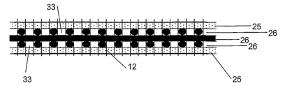
Figures 2 to 9 represent other embodiments of a composite according to the
present
invention comprising insulating layers, a fabric and a matrix.
In figure 2 the composite comprises three layers of individual yarns 26, e.g.
steel
yarns having a diameter of 0.175 mm, which are provided on their outside
surface with non
woven insulating layers 25. The non-woven layers 25 are provided between the
yarns and the
matrix 27, in particular a plastic (e.g. PVC) coat. Further represented is a
knitted connection
thread 12, interconnecting the insulating layer 25 and the layers of
individual metal yarns 26.
3o The figure further represents the free spaces 33, provided between the
individual elements in
the layers of individual elements 26.
Figure 3 represents another embodiment of a composite according to the present
invention. The composite comprises insulating layers 28, 29, which are
provided between the
CA 02541806 2006-03-07
WO 2005/023537 PCT/EP2003/010129
24
matrix 27 and two layers of individual elements, e.g. steel yarns 26 having a
diameter of
0.150 mm and surrounded with PETP fibers and glued together. The ratio
steel/PETP may
comprise 50/50. The upper insulating layer 28 may be a foam layer of e.g.
80g/m2, the lower
insulating layer 29 may be a plastic foil with a thickness of 0.10 mm. The
figure further
represents the free spaces 33, provided between the individual elements in the
layers of
individual elements 26.
Figure 4 represents another embodiment of a composite according to the present
invention. The composite comprises insulating layers 28, 29, e.g. a non woven
or a foil, that
are provided on the outside of three layers of individual yarns 26, e.g. steel
yarns 26 having a
1o diameter of 0.20 mm. Further represented is a knitted connection thread 12,
interconnecting
the insulating layer 28, 29 and the layers of individual metal yarns 26. The
composite further
comprises an aluminum foil 30, e.g. damped aluminum foil on a PETP foil, glued
32 on one of
the insulating layers 28 and a PVC or rubber coating layer 27, provided on
another insulating
layer 29. The composite is further provided with a releasable back sheet 31,
which is glued
32 on the aluminum foil 30. It is preferred that the glue does not react or
interfere with
softeners and/or ozone absorbers. The figure further represents the free
spaces 33, provided
between the individual elements in the layers of individual elements 26.
Figure 5 represents another embodiment of a composite according to the present
invention. The composite comprises insulating layers 28, 29, e.g. a non woven
and a foam
layer, that are provided on the outside of three layers of individual yarns
26, e.g, steel yarns
26 having a diameter of 0.20 mm. Further represented is a knitted connection
thread 12,
interconnecting the insulating layers 28, 29 and the layers of individual
metal yarns 26. The
composite further comprises an aluminum foil 30, e.g. damped aluminum foil on
a PETP foil,
glued 32 on one insulating layer 29, and a PVC or rubber coating layer 27,
provided on the
other insulating layer 28. Free spaces 33 are provided between the individual
elements in the
layers of individual elements 26.
Figure 6 represents another embodiment of a composite according to the present
invention. The composite comprises two insulating layer 28, 29, e.g. aluminum
foils, that are
provided on the outside of three layers of individual yarns 26, e.g. steel
yarns 26 having a
3o diameter of 0.20 mm. The composite further comprises a PVC or rubber
coating layer 27,
provided on either side of the insulating layers 28, 29. One of the insulating
layers 28 acts as
a positive conductor, while the other insulating layer 29 acts as a negative
conductor. When
an electrically conducting material, e.g. a knife, brings both conductive
layers in connection to
CA 02541806 2006-03-07
WO 2005/023537 PCT/EP2003/010129
each other, a signal is detected and transmitted to a control unit, which will
generate an alarm
signal. Free spaces 33 are provided between the individual elements in the
layers of
individual elements 26.
Figure 7 represents another embodiment of a composite according to the present
5 invention. The composite comprises four layers of individual elements 26,
preferably
consisting of metal or other conductive yarns (e.g. steel yarns). The
composite further
comprises an insulating layer 25 between two layers of reinforcement elements
26, so that a
part of the conductive yarns are insulated versus other conductive yarns. In
addition, a matrix
(coating) 27 is provided on the lower side and the upper side of the
composite, separated
io from a layer of reinforcement elements 26 by means of an insulating layer
28. The whole is
stitched or sewed together with a non conductive yarn 12. Free spaces 33 are
provided
between the individual elements in the layers of individual elements 26.
Figure 8 represents another embodiment of a composite according to the present
invention. The composite comprises two layers of individual elements 26,
preferably
15 consisting of metal or other conductive yarns (e.g. steel yarns). The
composite further
comprises insulating layers (e.g. non woven) 28, 29 on either side of the two
layers of
reinforcement elements 26. A coating (e.g. PVC, PVCC) is provided on top of
one of the
insulating layers 29. In addition, a damped or sputtered aluminum or other
metal foil 30 is
provided on top of one of the insulating layers 28. On top of this foil 30
glue 32 can be
2o provided, which is preferably resistant against softeners and ozone. The
whole is stitched or
sewed together with a non conductive yarn 12. Free spaces 33 are provided
between the
individual elements in the layers of individual elements 26.
Figure 9 represents another embodiment of a composite according to the present
invention. The composite comprises two layers of interwoven individual
elements 26,
25 preferably consisting of metal or other conductive yarns (e.g. steel
yarns). The composite
further comprises an insulating layer (e.g. non woven) 28 provided by means of
glue, a
thermoset or thermoplastic material 32 on one side of a layer of reinforcement
elements 26.
In addition, a conductive foil 30 is provided on top of the insulating layer
28 by means of glue,
a thermoset or thermoplastic material 32. On top of this foil 30 glue, or a
coating layer 27 can
3o be provided. Free spaces 33 are provided between the individual elements in
the layers of
individual elements 26.
CA 02541806 2006-03-07
WO 2005/023537 PCT/EP2003/010129
26
Hereunder, a few examples of fabrics, suitable for being used in the composite
according to the invention are provided.
In an example, a fabric may contain a warp and a weft. The warp ends may
contain
fully or partially insulated individual elements of conductive material, and
the weft may have
non-insulated or partially or fully insulated individual elements of
conductive material. An
example could be a steel thread covered with plastic as PVC, PP, PA, PETP,
PEB, PBT,
PVDF, or any mixture thereof or could be covered with an insulating yarn spun
or twisted or
braided around the thread.
In another example, as represented on Fig. 20, such fabric may comprise a weft
1o reinforcement individual element 1 and a warp reinforcement individual
element 2, a weft
binding individual element 3 and a warp binding individual element 4 whereby
the
reinforcement individual elements 1 and 2 do not bind each other or if wanted
only at wider
distances, e.g. 0.5, 1 or 3 mm, the way of binding can be changed and the
number of ends or
picks of as well individual elements and binding elements can be different
than one on any
row. In the represented example, the fabric comprises non-insulated weft
reinforcement
individual element 1 and insulated warp reinforcement individual element 2,
which are made
of conductive material. As soon as someone tries to cut through the presented
fabric, the
insulated warp ends will be brought into contact with the non-insulated weft
yarns, as the
insulation will disappear when cutting through. This contact will activate an
alarm.
2o In another example of a fabric according to the present invention is
represented on
Fig. 21. The fabric comprises two layers of non-woven individual elements 5, 6
of which one
serves as a positive layer 5, the other one as a negative or neutral layer 6.
They can be
insulated one versus the other by a insulating material 11, e.g. of
polyethylene, rubber, PVC,
polypropylene, polyamide, polyester or other coatings or any combination
thereof. The non-
woven elements comprise conductive material, e.g. conductive fibers or
conductive polymers.
In yet another example, as represented on Fig. 22, the fabric comprises
insulated
non-woven elements, insulated warp reinforcement individual elements 9 and
insulated bias
individual elements 10. Insulating knitted connection thread 12 is provided,
stitching through
the fabric and keeping all ends together by knitting. The cutting resistant
yarns are insulated
by at least one non-conductive layer 11 separating the conductive yarns
layers. Again,
contact can be made or disrupted by connecting the different layers of
conductive yarn ends.
Alternatively, the fabric may comprise, as represented on Fig. 23 insulated
non-woven
individual elements 9 and insulated bias individual elements 10, which are
made of
CA 02541806 2006-03-07
WO 2005/023537 PCT/EP2003/010129
27
conductive material. Insulating knitted connection thread 12 is provided,
stitching through the
fabric and keeping all ends together by knitting. The cutting resistant yarns
are insulated by at
least one non-conductive layer 11 separating the conductive yarns layers. To
have a good
contact the fabric may have one flat metal wire; preferably copper wire per
layer of yarns.
Fig. 22 and 23 provide a schematic representation for the concept of providing
a
knitted connection thread. A more detailed representation of the knitted
connection thread is
provided in fig. 24 and 25. Fig. 24 and 25 represent a fabric as in fig. 22
and 23, respectively
wherein the connection thread is knitted up and down through the fabric
forming knots or
connections 13, which are interconnected.
to Fig. 26 is a schematic representation of an activation mechanism of the
alarm system.
In this figure a reinforced fabric 18 is represented comprising at least two
conductive layer 14,
being insulated 16 in relation to each other. One of the layers acts as a
positive conductor
14, while the other layer acts as a negative conductor 15. When an
electrically conducting
material, e.g. a knife 17, brings both conductive layers in connection to each
other, a signal is
15 detected and transmitted to a control unit, which will generate an alarm
signal.
Fig. 27 is a schematic representation of the alarm system. A truck comprises a
canvas capable which is partly or wholly made of a fabric suitable for
activating an alarm
system according to the invention. The represented fabric is provided with a
sensor capable
of detecting a contact made in an electrical circuit or cutting off or closure
of an electrical
2o circuit provided in the fabric. Such detection is transmitted either
directly A or indirectly B, e.g.
via a satellite system 19 such as a global positioning system (GPS), to a
control unit 20,
which subsequently activates an alarm signal.
In a preferred embodiment of the present invention, the alarm system can be
interrupted or inactivated from a certain distance.
Figures 10b, 11c, 12b, 12c, 12d depict the force vectors in the plane of force
elucidating the enhanced cutting resistance aspect of the fabrics of the
present invention.
Figure 10b elucidates the force vector of a prior art fabric while the other
figures
depict the force vectors acting upon fabrics according to the invention. The
active (downward)
force vector, for example the result of a vandalism action by a cutting knife
on the yarns of the
3o present invention (figures 11-19) will be resolved in the plane of force
into a cutting force
vector acting perpendicular on the individual yarn and a rest force vector. It
is clear that the
rest force vector is zero on a fabric according to the prior art (figure 10a),
while on a fabric
according to the invention (figures 11-19) a positive rest force vector will
be present and
CA 02541806 2006-03-07
WO 2005/023537 PCT/EP2003/010129
28
therefore reducing the active downward force vector into a smaller cutting
force vector acting
perpendicular on the individual yarns. It is clear that due to the bias
directions and/or bias
layers, there is a considerable loss of the cutting force (perpendicular on
the yarns).
Furthermore, due to the weak connections between the individual elements or
yarns
and the downward directed active force vector, several individual elements
will be loosened
and will be collected together and form a resistant barrier presenting a high
cutting
resistance. It is clear that the cutting resistant value increases
surprisingly high with a fabric
according to the present invention whereof the examples are depicted in
figures 11-19.
Figure 11a shows a bias laid fabric comprising a longitudinal reinforcement
yarn up
21 and two bias directions 22, 23; three main enforcements bond together.
Figure 12a shows a four laid fabric comprising a longitudinal reinforcement
yarn up
21, a horizontal reinforcement yarn up 24 and two bias directions 22, 23; four
main
enforcements bond together.
Figure 13 shows a fabric according to invention comprising a weft
reinforcement
individual element 1 and a warp reinforcement individual element 2, a weft
direction binding
individual element 3 and a warp direction binding individual element 4 whereby
the
reinforcement individual elements 1 and 2 do not bind each other or if wanted
only at wider
distances, e.g. 3 mm, the way of binding can be changed and the number of ends
or picks of
as well individual elements and binding elements can be different than one on
any row.
2o Figure 14 shows a multi-axial insertion fabric comprising four main
directions, being
one warp 21, one weft 24 and two bias directions 22, 23 and a longitudinal
knitted connection
thread 12, stitching through the fabric and keeping all ends together by
knitting.
Figure 15 shows a multi-axial weft insertion fabric comprising three main
directions
being two bias directions 22, 23 and one weft direction 24, and a longitudinal
knitted
connection thread or yarn 12.
Figure 16 shows a laid fabric comprising two bias directions 22, 23 and one
horizontal
weft direction 24. The connections are made by chemical means, e.g. rubber,
PVC, PVA, PP,
PE, PBT, PVDF, mixtures thereof or other means of chemical bonding.
Figure 17 shows a laid fabric comprising four directions being one weft
direction 24,
one warp direction 21 and two bias directions 22, 23.
Figure 18 shows a bias laid fabric comprising two directions 22, 23.
Figure 19 shows a bias laid fabric comprising a longitudinal carrier yarn 4 up
and
under the two main directions 22, 23.
CA 02541806 2006-03-07
WO 2005/023537 PCT/EP2003/010129
29
All these laid fabrics are bond; this means the ends are kept together by
chemical or
fusion bonding or combinations thereof.
It will be evident that there are numerous other embodiments of the present
invention,
which, while not expressly described above, are clearly within the scope and
spirit of the
invention and are the equivalents thereof. The above description is therefore
to be considered
to be exemplary only, and the actual scope of the invention is to be
determined solely from
the appended claims.