Language selection

Search

Patent 2542057 Summary

Third-party information liability

Some of the information on this Web page has been provided by external sources. The Government of Canada is not responsible for the accuracy, reliability or currency of the information supplied by external sources. Users wishing to rely upon this information should consult directly with the source of the information. Content provided by external sources is not subject to official languages, privacy and accessibility requirements.

Claims and Abstract availability

Any discrepancies in the text and image of the Claims and Abstract are due to differing posting times. Text of the Claims and Abstract are posted:

  • At the time the application is open to public inspection;
  • At the time of issue of the patent (grant).
(12) Patent Application: (11) CA 2542057
(54) English Title: WELD PREP JOINT FOR ELECTRON BEAM OR LASER WELDING
(54) French Title: JOINT DE PREPARATION POUR SOUDURE AU FAISCEAU ELECTRONIQUE OU AU LASER
Status: Deemed Abandoned and Beyond the Period of Reinstatement - Pending Response to Notice of Disregarded Communication
Bibliographic Data
(51) International Patent Classification (IPC):
  • B23K 15/00 (2006.01)
  • B23K 33/00 (2006.01)
  • F01D 05/02 (2006.01)
(72) Inventors :
  • BURNETT, MARK EDWARD (United States of America)
  • SPIEGEL, LYLE B. (United States of America)
  • YEHLE, GARY EDWARD (United States of America)
  • BABCOCK, WILLIAM EDWARD (United States of America)
(73) Owners :
  • GENERAL ELECTRIC COMPANY
(71) Applicants :
  • GENERAL ELECTRIC COMPANY (United States of America)
(74) Agent: CRAIG WILSON AND COMPANY
(74) Associate agent:
(45) Issued:
(22) Filed Date: 2006-04-06
(41) Open to Public Inspection: 2006-10-13
Availability of licence: N/A
Dedicated to the Public: N/A
(25) Language of filing: English

Patent Cooperation Treaty (PCT): No

(30) Application Priority Data:
Application No. Country/Territory Date
11/104,404 (United States of America) 2005-04-13

Abstracts

English Abstract


A weld prep joint (22) for welding a pair of axially aligned first and second
machine
rotor forgings (14, 16) includes a first weld joint configuration in an end of
the first
rotor forging (14) including a first radial weld surface (26) and a first
axial rabbet
surface (28); a second weld joint configuration on an end of the second rotor
forging
(16) including a second radial weld surface (30) adapted to engage the first
radial
weld surface, a second axial rabbet surface (34) adapted to engage the first
axial
rabbet surface (28), and a third radial non-weld surface (33) extending
radially
inwardly of the second rabbet surface (34) and axially offset from the second
radial
weld surface (30).


Claims

Note: Claims are shown in the official language in which they were submitted.

WHAT IS CLAIMED IS:
1. A weld prep joint (22) for welding a pair of axially aligned first and
second
machine rotor forgings (14, 16) comprising:
a first weld joint configuration in an end of said first rotor forging (14)
including a
first radial weld surface (26) and a first axial rabbet surface (28);
a second weld joint configuration on an end of said second rotor forging (16)
including a second radial weld surface (30) adapted to engage said first
radial weld
surface (26), a second axial rabbet surface (34) adapted to engage said first
axial
rabbet surface (28), and a third radial non-weld surface (33) extending
radially
inwardly of said second rabbet surface (34) and axially offset from said
second radial
weld surface (30).
2. The weld prep joint of claim 1 wherein said first and second radial weld
surfaces
(26, 30) extend perpendicular to a longitudinal axis of said rotor forgings
(14, 16).
3. The weld prep joint of claim 2 wherein said third radial non-weld surface
(33)
extends parallel to said first and second radial weld surfaces (26, 30).
4. The weld prep joint of claim 1 wherein said third radial non-weld surface
(33) has
a radial length of two or more inches.
5. The weld prep joint of claim 1 wherein said first and second radial weld
surfaces
(26, 30) have a radial length of nine or more inches.
6. The weld prep joint of claim 4 wherein said first and second radial weld
surfaces
(26, 30) have a radial length of nine or more inches.
7. The weld prep joint of claim 1 and further comprising a circumferential
groove
(36) at an intersection of said second radial weld surface (30) and said
second axial
rabbet surface (34).

8. A method of welding a pair of axially-aligned rotor forgings (14, 16)
comprising:
(a) preparing weld prep joints on opposed ends of said rotor forgings, one of
said
joints including a first radial weld surface (16) and a first axial rabbet
surface (28), the
other of said joints including a second radial weld surface (30) and a second
axial
rabbet surface (34);
(b) joining said rotor forgings axially by a concentric interference fit
between said
first and second axial rabbet surfaces with said first and second radial weld
surfaces
engaged; and
(c) utilizing a laser or electron beam welding machine, welding the rotor
forgings
together, creating a weld area at least along said first and second radial
weld surfaces.
9. The method of claim 8 wherein said weld area extends radially inwardly of
said
first and second axial rabbet surfaces (28, 34).
10. The method of claim 8 wherein said first and second radial weld surfaces
(26, 30)
extend perpendicular to a longitudinal axis of said rotor forgings (14, 16).
6

Description

Note: Descriptions are shown in the official language in which they were submitted.


146521
CA 02542057 2006-04-06
WELD PREP JOINT FOR ELECTRON BEAM OR LASER WELDING
BACKGROUND OF THE INVENTION
This invention relates to electron beam or laser welding and, specifically, to
a steam
turbine rotor weld prep joint configured to facilitate a single pass full
penetration
fusion weld of axially-aligned rotor forgings using a focused high energy
beam.
Certain turbine rotors are comprised of a one piece "monoblock" forging. More
recently, to facilitate manufacture, shipment and assembly, discrete rotor
components
or forgings have been welded together to duplicate the original single
forging.
Welded rotors have not been completely satisfactory, however, due to
difficulty in
alignment and preparation of end faces for welding.
BRIEF DESCRIPTION OF THE INVENTION
This invention provides a unique weld prep joint for rotor forgings having two
geometry aspects that are particularly beneficial. First, the weld prep joint
is
configured to provide a rabbet interference fit for consistent concentric
assembly of
axially-aligned rotor forging components prior to welding. Secondly, the
radial
surfaces to be welded are offset from the rabbet surfaces such that the rabbet
surfaces
act as a backing, thus preventing burn-through and material drop-through from
forming on the rotor bore surfaces, thus eliminating internal rotor surface
rework.
In the exemplary embodiment, the rotor components are machined to provide
mating
axial rabbet surfaces on each of the two components creating a concentric
interference
fit between the axially-aligned forging components, thereby eliminating rotor
vibration. The arrangement also allows relative axial movement of the two
components prior to the welding operation.
More specifically, one of the rotor forging components is provided with a
first axial
rabbet surface and a radial weld surface. The other rotor forging component is
machined to include an underlying axial lip with a second axial rabbet surface
mated
to the axial rabbet surface of the first component, and a second radial weld
surface
adapted for engagement with the first radial weld surface of the first rotor
forging.
1

146521
CA 02542057 2006-04-06
The laser or electron beam welding process produces a radially extending weld
area
along the first and second radial weld surfaces, and also extending radially
into the lip
portion of the second rotor forging component. By extending the weld area
radially
inwardly of the mated rabbet surfaces (i.e., into a low stress area), the
potential for
stress cracking at the rabbet surface joint is minimized.
Accordingly, in one aspect, the present invention relates to a weld prep joint
for
welding a pair of axially aligned first and second machine rotor forgings
comprising a
first weld joint configuration in an end of the first rotor forging including
a first radial
weld surface and a first axial rabbet surface; a second weld joint
configuration on an
end of the second rotor forging including a second radial weld surface adapted
to
engage the first radial weld surface, a second axial rabbet surface adapted to
engage
the first axial rabbet surface, and a third radial non-weld surface extending
radially
inwardly of the second rabbet surface and axially offset from the second
radial weld
surface.
In another aspect, the invention relates to a welded rotor assembly comprising
a pair
of axially aligned rotor forgings joined by a circumferentially extending weld
area,
the weld area defined by a pair of axially aligned weld prep joints including
a first
weld joint configuration in an end of the first rotor forging having a first
radial weld
surface and a first axial rabbet surface, and a second weld joint
configuration on an
end of the second rotor forging including a second radial weld surface engaged
with
the first radial weld surface; a second axial rabbet surface engaged with the
first axial
rabbet surface; and a third radial non-weld surface extending radially
inwardly of the
second rabbet surface and axially offset from the second radial weld surface.
In still another aspect, the invention relates to a method of welding a pair
of axially-
aligned rotor forgings comprising (a) preparing weld prep joints on opposed
ends of
the rotor forgings, one of the joints including a first radial weld surface
and a first
axial rabbet surface, the other of the joints including a second radial weld
surface and
a second axial rabbet surface; (b) joining the rotor forgings axially by a
concentric
interference fit between the first and second axial rabbet surfaces with the
first and
second radial weld surfaces engaged; and (c) utilizing a laser or electron
beam
2

CA 02542057 2006-04-06
146521
welding machine, welding the rotor forgings together, creating a weld area at
least
along the first and second radial weld surfaces.
The invention will now be described in detail in connection with the drawings
identified below.
BRIEF DESCRIPTION OF THE DRAWINGS
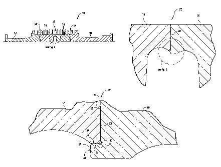
FIGURE 1 is a partial axial cross-section of a low pressure turbine rotor with
three
weld joints;
FIGURE 2 is an enlarged detail taken from Figure 1; and
FIGURE 3 is an enlarged detail taken from Figure 2.
DETAILED DESCRIPTION OF THE INVENTION
Referring to Figures 1 and 2, a rotor 10 for a turbine (e.g., a steam turbine)
is
constructed as a welded assembly of four rotor forging components (or simply,
forgings) 12, 14, 16 and 18 joined at three weld joints 20, 22 and 24. The
weld joints
in the exemplary embodiment are substantially identical, and only one need be
described in detail here. Weld joint 22 between components 14 and 16 is best
seen in
the enlarged detail of Figure 2. 'The rotor forging component 14 is machined
in a
weld prep process to include a first radial weld surface 26 perpendicular to
the
longitudinal axis of the rotor, and a first annular rabbet surface 28 (Figure
3) that
extends axially, parallel to the longitudinal axis.
The rotor forging component 16 is machined to include a second radial weld
surface
30 adapted to engage first weld surface 24, and an annular axial lip 32
radially inward
of the first rabbet surface 28. The lip 32 is formed to include a second
annular,
axially extending rabbet surface 34 adapted to engage rabbet surface 28, and a
forward face surface 33 of 2 or more inches in radial height forming an axial
termination surface of the lip. Surfaces 30 and 33 are thus axially offset by
a distance
equally the length of the lip 32.
3

146521
CA 02542057 2006-04-06
More specifically, the mating rabbet surfaces 28, 34 are machined so as to
obtain a
concentric interference fit between the axially-aligned forging components 14,
16. At
the same time, the radial facing weld surface 26, 30 abut each other at a
location
where the lip 32 joins with the remainder of the forging component, i.e., the
weld
location at the interface of radial weld surfaces 24, 30 is axially offset
from the mating
rabbet surfaces 28, 34 so that there is no need for a full penetration weld
that would
otherwise require rework to clean up burn-through and/or drop-through material
from
the welding process. An annular groove 36 at the juncture of the rabbet
surface 34
and radial weld surface 30 provides a receptor for molten metal during the
welding
process and is believed to assist in controlling the weld area termination
point within
the lip 32.
With the forging components located as shown in Figures 2 and 3, the laser or
electron beam welding tool (not shown) is rotated about the rotor to weld the
components along the radial interface. Figure 3 shows the weld area 38 of the
components that are made molten during the process and that form the weld. In
the
exemplary embodiment, the weld penetrates axially about .200 inch on each side
of
the radial interface at surfaces 24, 30. At the same time, the weld extends
radially
along the interface of surfaces 26, 30 nine or more inches and radially
inwardly
through about %2 the height of the lip 32. It is important that the radial
depth of the
weld extend below the mated rabbet surfaces, and thus below a relatively
higher stress
point. In other words, cracks are far less likely to propagate if the weld
terminates in
an area of low stress, such as that in the interior of the lip 32, radially
below the rabbet
surfaces. .
While the invention has been described in connection with what is presently
considered to be the most practical and preferred embodiment, it is to be
understood
that the invention is not to be limited to the disclosed embodiment, but on
the
contrary, is intended to cover various modifications and equivalent
arrangements
included within the spirit and scope of the appended claims.
4

Representative Drawing
A single figure which represents the drawing illustrating the invention.
Administrative Status

2024-08-01:As part of the Next Generation Patents (NGP) transition, the Canadian Patents Database (CPD) now contains a more detailed Event History, which replicates the Event Log of our new back-office solution.

Please note that "Inactive:" events refers to events no longer in use in our new back-office solution.

For a clearer understanding of the status of the application/patent presented on this page, the site Disclaimer , as well as the definitions for Patent , Event History , Maintenance Fee  and Payment History  should be consulted.

Event History

Description Date
Inactive: IPC expired 2014-01-01
Application Not Reinstated by Deadline 2011-04-06
Time Limit for Reversal Expired 2011-04-06
Deemed Abandoned - Failure to Respond to Maintenance Fee Notice 2010-04-06
Application Published (Open to Public Inspection) 2006-10-13
Inactive: Cover page published 2006-10-12
Inactive: First IPC assigned 2006-09-29
Inactive: IPC assigned 2006-09-29
Inactive: IPC assigned 2006-09-13
Letter Sent 2006-05-12
Inactive: Filing certificate - No RFE (English) 2006-05-12
Application Received - Regular National 2006-05-10

Abandonment History

Abandonment Date Reason Reinstatement Date
2010-04-06

Maintenance Fee

The last payment was received on 2009-03-23

Note : If the full payment has not been received on or before the date indicated, a further fee may be required which may be one of the following

  • the reinstatement fee;
  • the late payment fee; or
  • additional fee to reverse deemed expiry.

Patent fees are adjusted on the 1st of January every year. The amounts above are the current amounts if received by December 31 of the current year.
Please refer to the CIPO Patent Fees web page to see all current fee amounts.

Fee History

Fee Type Anniversary Year Due Date Paid Date
Registration of a document 2006-04-06
Application fee - standard 2006-04-06
MF (application, 2nd anniv.) - standard 02 2008-04-07 2008-03-28
MF (application, 3rd anniv.) - standard 03 2009-04-06 2009-03-23
Owners on Record

Note: Records showing the ownership history in alphabetical order.

Current Owners on Record
GENERAL ELECTRIC COMPANY
Past Owners on Record
GARY EDWARD YEHLE
LYLE B. SPIEGEL
MARK EDWARD BURNETT
WILLIAM EDWARD BABCOCK
Past Owners that do not appear in the "Owners on Record" listing will appear in other documentation within the application.
Documents

To view selected files, please enter reCAPTCHA code :


To view images, click a link in the Document Description column (Temporarily unavailable). To download the documents, select one or more checkboxes in the first column and then click the "Download Selected in PDF format (Zip Archive)" or the "Download Selected as Single PDF" button.

List of published and non-published patent-specific documents on the CPD .

If you have any difficulty accessing content, you can call the Client Service Centre at 1-866-997-1936 or send them an e-mail at CIPO Client Service Centre.

({010=All Documents, 020=As Filed, 030=As Open to Public Inspection, 040=At Issuance, 050=Examination, 060=Incoming Correspondence, 070=Miscellaneous, 080=Outgoing Correspondence, 090=Payment})


Document
Description 
Date
(yyyy-mm-dd) 
Number of pages   Size of Image (KB) 
Abstract 2006-04-05 1 20
Description 2006-04-05 4 201
Drawings 2006-04-05 3 31
Claims 2006-04-05 2 64
Representative drawing 2006-10-03 1 13
Courtesy - Certificate of registration (related document(s)) 2006-05-11 1 129
Filing Certificate (English) 2006-05-11 1 168
Reminder of maintenance fee due 2007-12-09 1 112
Courtesy - Abandonment Letter (Maintenance Fee) 2010-05-31 1 174
Reminder - Request for Examination 2010-12-06 1 117