Sélection de la langue

Search

Sommaire du brevet 2542057 

Énoncé de désistement de responsabilité concernant l'information provenant de tiers

Une partie des informations de ce site Web a été fournie par des sources externes. Le gouvernement du Canada n'assume aucune responsabilité concernant la précision, l'actualité ou la fiabilité des informations fournies par les sources externes. Les utilisateurs qui désirent employer cette information devraient consulter directement la source des informations. Le contenu fourni par les sources externes n'est pas assujetti aux exigences sur les langues officielles, la protection des renseignements personnels et l'accessibilité.

Disponibilité de l'Abrégé et des Revendications

L'apparition de différences dans le texte et l'image des Revendications et de l'Abrégé dépend du moment auquel le document est publié. Les textes des Revendications et de l'Abrégé sont affichés :

  • lorsque la demande peut être examinée par le public;
  • lorsque le brevet est émis (délivrance).
(12) Demande de brevet: (11) CA 2542057
(54) Titre français: JOINT DE PREPARATION POUR SOUDURE AU FAISCEAU ELECTRONIQUE OU AU LASER
(54) Titre anglais: WELD PREP JOINT FOR ELECTRON BEAM OR LASER WELDING
Statut: Réputée abandonnée et au-delà du délai pour le rétablissement - en attente de la réponse à l’avis de communication rejetée
Données bibliographiques
(51) Classification internationale des brevets (CIB):
  • B23K 15/00 (2006.01)
  • B23K 33/00 (2006.01)
  • F01D 05/02 (2006.01)
(72) Inventeurs :
  • BURNETT, MARK EDWARD (Etats-Unis d'Amérique)
  • SPIEGEL, LYLE B. (Etats-Unis d'Amérique)
  • YEHLE, GARY EDWARD (Etats-Unis d'Amérique)
  • BABCOCK, WILLIAM EDWARD (Etats-Unis d'Amérique)
(73) Titulaires :
  • GENERAL ELECTRIC COMPANY
(71) Demandeurs :
  • GENERAL ELECTRIC COMPANY (Etats-Unis d'Amérique)
(74) Agent: CRAIG WILSON AND COMPANY
(74) Co-agent:
(45) Délivré:
(22) Date de dépôt: 2006-04-06
(41) Mise à la disponibilité du public: 2006-10-13
Licence disponible: S.O.
Cédé au domaine public: S.O.
(25) Langue des documents déposés: Anglais

Traité de coopération en matière de brevets (PCT): Non

(30) Données de priorité de la demande:
Numéro de la demande Pays / territoire Date
11/104,404 (Etats-Unis d'Amérique) 2005-04-13

Abrégés

Abrégé anglais


A weld prep joint (22) for welding a pair of axially aligned first and second
machine
rotor forgings (14, 16) includes a first weld joint configuration in an end of
the first
rotor forging (14) including a first radial weld surface (26) and a first
axial rabbet
surface (28); a second weld joint configuration on an end of the second rotor
forging
(16) including a second radial weld surface (30) adapted to engage the first
radial
weld surface, a second axial rabbet surface (34) adapted to engage the first
axial
rabbet surface (28), and a third radial non-weld surface (33) extending
radially
inwardly of the second rabbet surface (34) and axially offset from the second
radial
weld surface (30).

Revendications

Note : Les revendications sont présentées dans la langue officielle dans laquelle elles ont été soumises.


WHAT IS CLAIMED IS:
1. A weld prep joint (22) for welding a pair of axially aligned first and
second
machine rotor forgings (14, 16) comprising:
a first weld joint configuration in an end of said first rotor forging (14)
including a
first radial weld surface (26) and a first axial rabbet surface (28);
a second weld joint configuration on an end of said second rotor forging (16)
including a second radial weld surface (30) adapted to engage said first
radial weld
surface (26), a second axial rabbet surface (34) adapted to engage said first
axial
rabbet surface (28), and a third radial non-weld surface (33) extending
radially
inwardly of said second rabbet surface (34) and axially offset from said
second radial
weld surface (30).
2. The weld prep joint of claim 1 wherein said first and second radial weld
surfaces
(26, 30) extend perpendicular to a longitudinal axis of said rotor forgings
(14, 16).
3. The weld prep joint of claim 2 wherein said third radial non-weld surface
(33)
extends parallel to said first and second radial weld surfaces (26, 30).
4. The weld prep joint of claim 1 wherein said third radial non-weld surface
(33) has
a radial length of two or more inches.
5. The weld prep joint of claim 1 wherein said first and second radial weld
surfaces
(26, 30) have a radial length of nine or more inches.
6. The weld prep joint of claim 4 wherein said first and second radial weld
surfaces
(26, 30) have a radial length of nine or more inches.
7. The weld prep joint of claim 1 and further comprising a circumferential
groove
(36) at an intersection of said second radial weld surface (30) and said
second axial
rabbet surface (34).

8. A method of welding a pair of axially-aligned rotor forgings (14, 16)
comprising:
(a) preparing weld prep joints on opposed ends of said rotor forgings, one of
said
joints including a first radial weld surface (16) and a first axial rabbet
surface (28), the
other of said joints including a second radial weld surface (30) and a second
axial
rabbet surface (34);
(b) joining said rotor forgings axially by a concentric interference fit
between said
first and second axial rabbet surfaces with said first and second radial weld
surfaces
engaged; and
(c) utilizing a laser or electron beam welding machine, welding the rotor
forgings
together, creating a weld area at least along said first and second radial
weld surfaces.
9. The method of claim 8 wherein said weld area extends radially inwardly of
said
first and second axial rabbet surfaces (28, 34).
10. The method of claim 8 wherein said first and second radial weld surfaces
(26, 30)
extend perpendicular to a longitudinal axis of said rotor forgings (14, 16).
6

Description

Note : Les descriptions sont présentées dans la langue officielle dans laquelle elles ont été soumises.

146521
CA 02542057 2006-04-06
WELD PREP JOINT FOR ELECTRON BEAM OR LASER WELDING
BACKGROUND OF THE INVENTION
This invention relates to electron beam or laser welding and, specifically, to
a steam
turbine rotor weld prep joint configured to facilitate a single pass full
penetration
fusion weld of axially-aligned rotor forgings using a focused high energy
beam.
Certain turbine rotors are comprised of a one piece "monoblock" forging. More
recently, to facilitate manufacture, shipment and assembly, discrete rotor
components
or forgings have been welded together to duplicate the original single
forging.
Welded rotors have not been completely satisfactory, however, due to
difficulty in
alignment and preparation of end faces for welding.
BRIEF DESCRIPTION OF THE INVENTION
This invention provides a unique weld prep joint for rotor forgings having two
geometry aspects that are particularly beneficial. First, the weld prep joint
is
configured to provide a rabbet interference fit for consistent concentric
assembly of
axially-aligned rotor forging components prior to welding. Secondly, the
radial
surfaces to be welded are offset from the rabbet surfaces such that the rabbet
surfaces
act as a backing, thus preventing burn-through and material drop-through from
forming on the rotor bore surfaces, thus eliminating internal rotor surface
rework.
In the exemplary embodiment, the rotor components are machined to provide
mating
axial rabbet surfaces on each of the two components creating a concentric
interference
fit between the axially-aligned forging components, thereby eliminating rotor
vibration. The arrangement also allows relative axial movement of the two
components prior to the welding operation.
More specifically, one of the rotor forging components is provided with a
first axial
rabbet surface and a radial weld surface. The other rotor forging component is
machined to include an underlying axial lip with a second axial rabbet surface
mated
to the axial rabbet surface of the first component, and a second radial weld
surface
adapted for engagement with the first radial weld surface of the first rotor
forging.
1

146521
CA 02542057 2006-04-06
The laser or electron beam welding process produces a radially extending weld
area
along the first and second radial weld surfaces, and also extending radially
into the lip
portion of the second rotor forging component. By extending the weld area
radially
inwardly of the mated rabbet surfaces (i.e., into a low stress area), the
potential for
stress cracking at the rabbet surface joint is minimized.
Accordingly, in one aspect, the present invention relates to a weld prep joint
for
welding a pair of axially aligned first and second machine rotor forgings
comprising a
first weld joint configuration in an end of the first rotor forging including
a first radial
weld surface and a first axial rabbet surface; a second weld joint
configuration on an
end of the second rotor forging including a second radial weld surface adapted
to
engage the first radial weld surface, a second axial rabbet surface adapted to
engage
the first axial rabbet surface, and a third radial non-weld surface extending
radially
inwardly of the second rabbet surface and axially offset from the second
radial weld
surface.
In another aspect, the invention relates to a welded rotor assembly comprising
a pair
of axially aligned rotor forgings joined by a circumferentially extending weld
area,
the weld area defined by a pair of axially aligned weld prep joints including
a first
weld joint configuration in an end of the first rotor forging having a first
radial weld
surface and a first axial rabbet surface, and a second weld joint
configuration on an
end of the second rotor forging including a second radial weld surface engaged
with
the first radial weld surface; a second axial rabbet surface engaged with the
first axial
rabbet surface; and a third radial non-weld surface extending radially
inwardly of the
second rabbet surface and axially offset from the second radial weld surface.
In still another aspect, the invention relates to a method of welding a pair
of axially-
aligned rotor forgings comprising (a) preparing weld prep joints on opposed
ends of
the rotor forgings, one of the joints including a first radial weld surface
and a first
axial rabbet surface, the other of the joints including a second radial weld
surface and
a second axial rabbet surface; (b) joining the rotor forgings axially by a
concentric
interference fit between the first and second axial rabbet surfaces with the
first and
second radial weld surfaces engaged; and (c) utilizing a laser or electron
beam
2

CA 02542057 2006-04-06
146521
welding machine, welding the rotor forgings together, creating a weld area at
least
along the first and second radial weld surfaces.
The invention will now be described in detail in connection with the drawings
identified below.
BRIEF DESCRIPTION OF THE DRAWINGS
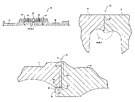
FIGURE 1 is a partial axial cross-section of a low pressure turbine rotor with
three
weld joints;
FIGURE 2 is an enlarged detail taken from Figure 1; and
FIGURE 3 is an enlarged detail taken from Figure 2.
DETAILED DESCRIPTION OF THE INVENTION
Referring to Figures 1 and 2, a rotor 10 for a turbine (e.g., a steam turbine)
is
constructed as a welded assembly of four rotor forging components (or simply,
forgings) 12, 14, 16 and 18 joined at three weld joints 20, 22 and 24. The
weld joints
in the exemplary embodiment are substantially identical, and only one need be
described in detail here. Weld joint 22 between components 14 and 16 is best
seen in
the enlarged detail of Figure 2. 'The rotor forging component 14 is machined
in a
weld prep process to include a first radial weld surface 26 perpendicular to
the
longitudinal axis of the rotor, and a first annular rabbet surface 28 (Figure
3) that
extends axially, parallel to the longitudinal axis.
The rotor forging component 16 is machined to include a second radial weld
surface
30 adapted to engage first weld surface 24, and an annular axial lip 32
radially inward
of the first rabbet surface 28. The lip 32 is formed to include a second
annular,
axially extending rabbet surface 34 adapted to engage rabbet surface 28, and a
forward face surface 33 of 2 or more inches in radial height forming an axial
termination surface of the lip. Surfaces 30 and 33 are thus axially offset by
a distance
equally the length of the lip 32.
3

146521
CA 02542057 2006-04-06
More specifically, the mating rabbet surfaces 28, 34 are machined so as to
obtain a
concentric interference fit between the axially-aligned forging components 14,
16. At
the same time, the radial facing weld surface 26, 30 abut each other at a
location
where the lip 32 joins with the remainder of the forging component, i.e., the
weld
location at the interface of radial weld surfaces 24, 30 is axially offset
from the mating
rabbet surfaces 28, 34 so that there is no need for a full penetration weld
that would
otherwise require rework to clean up burn-through and/or drop-through material
from
the welding process. An annular groove 36 at the juncture of the rabbet
surface 34
and radial weld surface 30 provides a receptor for molten metal during the
welding
process and is believed to assist in controlling the weld area termination
point within
the lip 32.
With the forging components located as shown in Figures 2 and 3, the laser or
electron beam welding tool (not shown) is rotated about the rotor to weld the
components along the radial interface. Figure 3 shows the weld area 38 of the
components that are made molten during the process and that form the weld. In
the
exemplary embodiment, the weld penetrates axially about .200 inch on each side
of
the radial interface at surfaces 24, 30. At the same time, the weld extends
radially
along the interface of surfaces 26, 30 nine or more inches and radially
inwardly
through about %2 the height of the lip 32. It is important that the radial
depth of the
weld extend below the mated rabbet surfaces, and thus below a relatively
higher stress
point. In other words, cracks are far less likely to propagate if the weld
terminates in
an area of low stress, such as that in the interior of the lip 32, radially
below the rabbet
surfaces. .
While the invention has been described in connection with what is presently
considered to be the most practical and preferred embodiment, it is to be
understood
that the invention is not to be limited to the disclosed embodiment, but on
the
contrary, is intended to cover various modifications and equivalent
arrangements
included within the spirit and scope of the appended claims.
4

Dessin représentatif
Une figure unique qui représente un dessin illustrant l'invention.
États administratifs

2024-08-01 : Dans le cadre de la transition vers les Brevets de nouvelle génération (BNG), la base de données sur les brevets canadiens (BDBC) contient désormais un Historique d'événement plus détaillé, qui reproduit le Journal des événements de notre nouvelle solution interne.

Veuillez noter que les événements débutant par « Inactive : » se réfèrent à des événements qui ne sont plus utilisés dans notre nouvelle solution interne.

Pour une meilleure compréhension de l'état de la demande ou brevet qui figure sur cette page, la rubrique Mise en garde , et les descriptions de Brevet , Historique d'événement , Taxes périodiques et Historique des paiements devraient être consultées.

Historique d'événement

Description Date
Inactive : CIB expirée 2014-01-01
Demande non rétablie avant l'échéance 2011-04-06
Le délai pour l'annulation est expiré 2011-04-06
Réputée abandonnée - omission de répondre à un avis sur les taxes pour le maintien en état 2010-04-06
Demande publiée (accessible au public) 2006-10-13
Inactive : Page couverture publiée 2006-10-12
Inactive : CIB en 1re position 2006-09-29
Inactive : CIB attribuée 2006-09-29
Inactive : CIB attribuée 2006-09-13
Lettre envoyée 2006-05-12
Inactive : Certificat de dépôt - Sans RE (Anglais) 2006-05-12
Demande reçue - nationale ordinaire 2006-05-10

Historique d'abandonnement

Date d'abandonnement Raison Date de rétablissement
2010-04-06

Taxes périodiques

Le dernier paiement a été reçu le 2009-03-23

Avis : Si le paiement en totalité n'a pas été reçu au plus tard à la date indiquée, une taxe supplémentaire peut être imposée, soit une des taxes suivantes :

  • taxe de rétablissement ;
  • taxe pour paiement en souffrance ; ou
  • taxe additionnelle pour le renversement d'une péremption réputée.

Les taxes sur les brevets sont ajustées au 1er janvier de chaque année. Les montants ci-dessus sont les montants actuels s'ils sont reçus au plus tard le 31 décembre de l'année en cours.
Veuillez vous référer à la page web des taxes sur les brevets de l'OPIC pour voir tous les montants actuels des taxes.

Historique des taxes

Type de taxes Anniversaire Échéance Date payée
Enregistrement d'un document 2006-04-06
Taxe pour le dépôt - générale 2006-04-06
TM (demande, 2e anniv.) - générale 02 2008-04-07 2008-03-28
TM (demande, 3e anniv.) - générale 03 2009-04-06 2009-03-23
Titulaires au dossier

Les titulaires actuels et antérieures au dossier sont affichés en ordre alphabétique.

Titulaires actuels au dossier
GENERAL ELECTRIC COMPANY
Titulaires antérieures au dossier
GARY EDWARD YEHLE
LYLE B. SPIEGEL
MARK EDWARD BURNETT
WILLIAM EDWARD BABCOCK
Les propriétaires antérieurs qui ne figurent pas dans la liste des « Propriétaires au dossier » apparaîtront dans d'autres documents au dossier.
Documents

Pour visionner les fichiers sélectionnés, entrer le code reCAPTCHA :


Pour visualiser une image, cliquer sur un lien dans la colonne description du document (Temporairement non-disponible). Pour télécharger l'image (les images), cliquer l'une ou plusieurs cases à cocher dans la première colonne et ensuite cliquer sur le bouton "Télécharger sélection en format PDF (archive Zip)" ou le bouton "Télécharger sélection (en un fichier PDF fusionné)".

Liste des documents de brevet publiés et non publiés sur la BDBC .

Si vous avez des difficultés à accéder au contenu, veuillez communiquer avec le Centre de services à la clientèle au 1-866-997-1936, ou envoyer un courriel au Centre de service à la clientèle de l'OPIC.

({010=Tous les documents, 020=Au moment du dépôt, 030=Au moment de la mise à la disponibilité du public, 040=À la délivrance, 050=Examen, 060=Correspondance reçue, 070=Divers, 080=Correspondance envoyée, 090=Paiement})


Description du
Document 
Date
(aaaa-mm-jj) 
Nombre de pages   Taille de l'image (Ko) 
Abrégé 2006-04-05 1 20
Description 2006-04-05 4 201
Dessins 2006-04-05 3 31
Revendications 2006-04-05 2 64
Dessin représentatif 2006-10-03 1 13
Courtoisie - Certificat d'enregistrement (document(s) connexe(s)) 2006-05-11 1 129
Certificat de dépôt (anglais) 2006-05-11 1 168
Rappel de taxe de maintien due 2007-12-09 1 112
Courtoisie - Lettre d'abandon (taxe de maintien en état) 2010-05-31 1 174
Rappel - requête d'examen 2010-12-06 1 117