Note: Descriptions are shown in the official language in which they were submitted.
i
CA 02542331 2006-04-07
Cylindrical Baling Press
BACKGROUND
1. Field of the Invention
The present invention relates to a cylindrical baling press used in
agriculture for the forming of cylindrical bales of harvested crop material.
More
specifically, it relates to an improvement that reduces jamming and tracking
problems
by freeing entrapped crop material from a belt of the baling press.
2. Description of Related Art
Cylindrical baling presses have a baling chamber enclosed by lateral
walls, with the other surfaces being enclosed in part by one or more belts
guided
around rollers so as to form loops and an opening for crop material. At the
locations
where the belts) move away from the cylindrical bale, crop material tends to
become
entrapped within interior spaces of the loops. This can lead to problems with
jamming
and/or tracking of the belt(s). In the book "Fundamentals of machine
operations, hay
and forage harvesting", FMO 141 B, D-00, p. 153, it is suggested that the
lateral
surfaces be left open. However, this solution is not effective until the
baling process is
nearly complete, at which point the risk of jamming and tracking problems is
greatly
reduced. In addition, this solution is most effective where the belts) are
approaching
the cylindrical bale, in which location the above problems rarely occur.
The present invention seeks to solve these issues by providing a general
means to avoid accumulations of crop material in loops or between belt
sections of a
cylindrical baling press.
1
CA 02542331 2006-04-07
SUMMARY
The present invention provides a means by which crop material
accumulated in a belt loop against a lateral wall, and engaged by peripheral
surfaces of
a rotating cylindrical bale, is removed from the interior space of the belt
loop. The
present invention is not limited to belts, but encompasses any tensile means
which
may surround a baling chamber.
According to one embodiment, the lateral wall includes an opening near
a roller where crop material then accumulates. Removal occurs between a
forward
edge of the lateral wall opening and the space between the lateral wall and
the roll.
Crop material presses directly against an end face of the rotating cylindrical
bale and is
carried along by the bale and ejected through the opening.
In an alternate embodiment, a recess or outward bulge of the lateral
wall, rather than an opening, is provided. As a result, the crop material will
be fed to
the end face of the cylindrical bale and be held adjacent to the end face
until it
becomes absorbed into the bale. The shape of the recess may be, for example, a
wedge shape, which progressively approaches a peripheral surface, where the
crop
material is forced against the bale.
While most of the crop material is withdrawn from within the belt loop, not
all of the crop material is necessarily fed to the end face of the cylindrical
bale. To
move all of the crop material to the end face, a conveying device may be
provided to
feed it back into the bale. The conveying device may be of an active type (for
example
screws, paddles, blowers, or the like) or may be passive (for example a chute
or the
like). Screw conveyors may convey in the axial direction or the tangential
direction.
2
i
CA 02542331 2006-04-07
In addition, removed material may be re-fed into the bale by depositing
the removed material onto the baler's intake and feed device. The intake and
feed
device is usually located below the opening or recess. This makes it simple
for said
crop material to be conveyed back into the baling process.
In order to successfully handle particularly tough, wet, and/or rigid crop
material, a fragmenting device may also be provided near the end of the
roller. This
device will cut up long stalks and the like and enable them to be incorporated
into
the bale. The fragmenting device may be fixed to the roller itself, or may
cooperate
with the roller, for example, by means of blades on the roll and/or apart from
the roll.
Alternatively, chopping devices, rotary blades, or the like may be provided
which are
separately driven but which provide the same function.
Further objects, features and advantages of this invention will become
readily apparent to persons skilled in the art after a review of the following
description, with reference to the drawings and claims that are appended to
and
form a part of this specification.
BRIEF DESCRIPTION OF THE DRAWINGS
An exemplary embodiment of the present invention is illustrated in the
drawings, which embodiment will be described in more detail hereinbelow.
Fig. 1 is a side view of a cylindrical baling press according to the
present invention;
Fig. 2 is a top detail view of the baling press of Fig. 1 showing the end
of a roller and a protruding section of a lateral wall;
3
CA 02542331 2006-04-07
Fig. 3 is a top view of the cylindrical baling press of Fig. 1 showing a
conveying device near the end of the roller; and
Fig. 4 is a side view of the roll of Fig. 2 of the cylindrical baling press
showing a fragmenting device and an open section of the lateral wall.
DETAILED DESCRIPTION
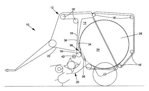
A conventional, towed cylindrical baling press according to the present
invention is illustrated in Fig. 1 and designated at 10. It includes a vehicle
frame 12,
lateral walls 14, rollers 16 and 16', a belt 18, an intake and feed device 20
and a
baling chamber 24. The baling chamber 24 creates bales out of crop materials,
for
example, hay, straw, silage, or other crops. The baling chamber 24 is capable
of
varying in size, although other embodiments may have a baling chamber 24 with
fixed dimensions. In the present embodiment, the size of the baling chamber 24
is
varied by shifting the position of the rollers 16 and 16' in response to the
size of a
cylindrical bale 28 being formed within the baling chamber 24. In some
embodiments the baling press 10 may be industrial in scale and stationary,
used, for
example, to process wastes, wood, or any other material where forming into a
bale
may be useful for storage, transport or disposal.
Looking more closely at the vehicle chassis 12 of the towed embodiment
shown in Fig. 1, it includes an axle with wheels, and a tow shaft for coupling
it behind a
tractor vehicle, for example, a farm tractor. The vehicle frame 12 also
includes a
framework 22 which supports lateral walls 14, the rollers 16 and 16' and other
devices
(not illustrated), such as holding, confining, and positioning and binding
devices.
4
CA 02542331 2006-04-07
The lateral walls 14 are large enough to approximately cover the end
faces of the baling chamber 24. Depending on the general configuration of the
apparatus, the lateral walls 14 may be segmented parts of the vehicle chassis
12 or
may be separate metal plates which cover the entire end face and may be
movable or
even controllable. Regardless of the configuration of the lateral walls 14,
the present
invention includes an open section 26 located near the outboard end of the
roller 16.
The open section 26 is configured to avoid contact with an end face of a
cylindrical
bale 28.
The rollers 16 and 16' have various functions and therefore different
designs and configurations. In general, all of the rollers 16 and 16' have a
roller
body 30 rotatably mounted to the framework 22 or lateral walls 14, by a shaft
32
(see Fig. 2). Some of the rollers 16 and 16' are disposed on a stressing arm
(not
shown), configured to move the rollers 16 and 16' and hold the belt 18 under
constant tension.
According to the present invention, the roller 16 is of primary
significance. The roller 16 is configured such that, after being routed around
the
baling chamber 24, the belt 18 is guided over and partially around the roller
16 and up
to one of the other rollers 16'. Consequently, two belt sections 34 and 36
(see Fig. 2)
are formed, defining a space 38 in between. The roller 16 is arranged such
that one of
the belt sections 34 and 36 moves away from the outer circumferential surface
of the
cylindrical bale 28. This presents the risk that the belt 18 will carry away
crop material
and cause it to enter the space 38, leading jamming of the rollers 16 and 16'
and/or
tracking problems with the belt 18. Jamming regularly occurs near the end of
the roller
16 toward the lateral walls 14.
i
CA 02542331 2006-04-07
The rollers 16 and 16' may have different lengths. However, at least the
shaft 32 of the roller 16 extends laterally beyond the baling chamber 24. In
Fig. 4, an
embodiment is illustrated wherein the end region of the roller 16 includes a
fragmenting
device 40, described below in more detail.
The belt 18 may be a full-surfaced belt 18 which extends over nearly
the entire width of the baling chamber 24. Alternatively, it may be configured
as a
plurality of belts 18 arranged in parallel with a minimal separation between
the belts
such that nearly the entire width of the baling chamber 24 is covered (see
Fig. 3). In
either configuration, the belt 18 is guided by the roller 16, and redirected
by
approximately 180°.
At the beginning of the baling process the belt 18 contacts the roller 16
directly, because they extend from below the roller 16 to the side of the
neighboring
roller 16' adjacent to the baling chamber 24. Initially the baling chamber 24
is kept to
a minimal size. Increasing resistance applied to a lower belt by a tensioning
device
(not shown) forms a dense bale. The belts 18 cannot extend fully to the
lateral walls
14 and, if a plurality of belts 18 are employed, the belts 18 may even move
away from
the lateral walls 14. This creates the possibility that the crop material may
leave the
baling chamber 24 and enter the space 38. In addition, there is a risk that
the crop
material will penetrate in between the belts 18 and the respective rollers 16
and 16' and
become trapped within the space 38. A conveying device 42 may also be provided
(Fig. 3), near the roller 16.
The intake and feed device 20 is of a conventional design. It includes
a pick-up and, in the embodiment illustrated, a rotor (which may be in the
form of a
crop cutting device) which conveys the pressed crop material from the pick-up
into
6
CA 02542331 2006-04-07
the baling chamber 24. The intake and feed device 20 is disposed below the tow
roller 16 and, in the embodiment shown, is wider than the baling chamber 24.
The fragmenting device 40 (see Fig. 4) includes cutters 46 (with cutting
edges) which extend radially and run along the axis of the roller body 30. In
the
present embodiment, these cutters 46 are positioned relative to a cooperating
cutter
48 to cut plant stalks and the like into smaller pieces. The cooperating
cutter 48 may
be mounted to either the framework 22 or the lateral walls 14. Instead of
mounting
the cutters 46, along the axis of the roller body 30, they may also be aligned
at an
angle to the axis or along a spiral or helical path. The cutters 46 are an
optional
feature included only if conditions so require.
The conveying device 42 is in the form of a screw conveyor driven, for
example, by belts, a gear drive, electrical motor, or hydraulic motor. In
other
embodiments, the conveying device 42 may be undriven if configured to rotate
by
contacting the crops being fed into the baling chamber 24 by the intake and
feed
device 20. If the conveying device 42 is in the form of a screw conveyor (as
shown in
Figs. 1 and 4), it moves the crop material along its axial length toward the
center of the
baling press 10. The conveying device 42 may be arranged to move crops on
either its
upper or lower side, depending on where the crops are to be deposited. For
most
applications, other than particularly difficult conditions, the conveying
device 42 is not
necessary.
The open section 26 is located on the lateral wall 14 relative to the
space 38 and the end of the roller 16. In the embodiment illustrated, the open
section 26 is configured as a protrusion in the lateral wall 14 defining an
opening.
The protrusion is arranged to extend away from the end face of the cylindrical
bale
7
CA 02542331 2006-04-07
28 and the lateral wall 14 and directed toward the end of the roller 16. The
opening
within the open section 26 permits the crop material trapped within the space
38,
which is being moved or agitated by the belt 18, to be ejected either downward
onto
the intake and feed device 20 or be directed by the protrusion into the
cylindrical bale
28. The intake and feed device 20 conveys the crop material formerly trapped
within
the space 38 to be conveyed back into the chamber 24, where it is picked up by
the
cylindrical bale 28, preventing it from causing further problems or being
wasted.
In an alternate embodiment (not shown), the open section 26 does not
include the protrusion extending away from the lateral wall 14, but rather
just includes
the opening. In this embodiment, a forward edge 44 (see Fig. 4) of the lateral
wall 14
extends through an arc across the circular surface formed by the side of the
cylindrical
bale 28, creating an open circular segment in the lateral wall 14. The shape
of the
opening need not be that of an arc; any shape suitable to allow entrapped crop
material to escape the space 38 may be provided. In this embodiment, all crop
material feed from the space 38 is ejected onto the intake and feed device 20
and
returned to the baling chamber 24. In Fig. 4, the open section 26 is shown
only in a
partial view to show the edge 44 and illustrate the embodiment described
above.
As a person skilled in the art will readily appreciate, the above
description is meant as an illustration of implementation of the principles
this
invention. This description is not intended to limit the scope or application
of this
invention in that the invention is susceptible to modification, variation and
change,
without departing from spirit of this invention, as defined in the following
claims.
8