Note: Descriptions are shown in the official language in which they were submitted.
CA 02542398 1997-12-17
_ 1 _
Description
AUTOMATICALLY ADJUSTABLE PASSENGER MIRROR FOR A TRAILERED
VEHICLE
Technical Field
The invention relates to an assembly for
automatically rotating a vehicle rear view mirror. More
specifically, the invention relates to both an assembly
for automatically rotating a rear view mirror mounted on a
passenger side of a vehicle comprising a tractor hauling
or semi-detached trailer, and to the rear view mirror
itself.
Background Art
Trailered vehicles are well-known. Referring to Fig.
1, a trailered vehicle 20 comprises a semi-detached
trailer 22 mounted to a tractor 24. Trailer 22 is mounted
at a hitching point 26, typically referred to as a "fifth
wheel," positioned at a rear end 28 of the tractor's
chassis 30. The tractor and trailer generally align to
define an imaginary axis 32. A passenger-side rear view
mirror 34 typically is mounted on a passenger-side door of
the tractor, and positioned generally in alignment with
the axis 32, so that the driver can see the passenger-side
rear corner 36 of the trailer 22. The driver typically
adjusts this passenger-side mirror 34 either electrically,
or by hand, according to the length of the trailer 22.
The above-described relationship is shown in Fig. 1(a),
depicting the right hand side as the passenger side, as is
common for example in the United States, Canada and
continental Europe. The driver's field of vision in the
passenger-side mirror is depicted by reference number 38.
A problem occurs when the driver enters a turn,
either going forward or reversing. As the tractor turns,
the
CA 02542398 1997-12-17
-2-
trailer pivots with respect to the tractor, forming an angle
therebetween. The passenger-side rear view mirror, however,
remain stationary. The trailer 22 therefore blocks the field
of vision 38, causing the driver to lose sight of the
passenger-side rear corner 36 of the trailer, along with any
object in the vicinity. This problem is depicted in
Fig. 1(b). Tighter turns obviously exacerbate this problem.
The resultant loss of rear visibility creates
potentially dangerous situations. Whether driving on winding
roads, or attempting to back the trailer into a parking lot
or a loading dock, the driver's inability to see other
vehicles, persons, or other objects in his passenger-side
mirror can result in property damage or more serious
accidents.
Reports published in 1994 indicate that out of 330,000
reported truck crashes in the U.S. in 1991, 19.1
(approximately 198,000) of these accidents involved backing,
turning, lane-changing, or merging maneuvers by trailered
vehicles. These crashes accounted for 1.0$ of all
fatalities, 10.8$ of injuries, and 6.3~ of costs for
trailered vehicle accidents that year, with total direct
monetary losses estimated at over $250 million.
A number of commercially available warning systems exist
that give a driver a warning of objects behind his truck
during a turn. Despite the desirability of such systems,
surveys of professional truck drivers have noted several
shortcomings with the available systems. For example,
existing devices are not easy to install. Another problem
exists with the reliability of the existing systems,
including damage to the systems while in use. Another
problem is the difficulty of using the existing systems. In
short, existing systems to detect and warn drivers of objects
behind a truck have limited areas of coverage, provide
inconsistent warnings, and rarely are used.
CA 02542398 1997-12-17
-3-
A better solution is to enable the driver to rely on his
passenger-side rear view mirror, by providing the mirror with
the capability to rotate in response to a vehicle turn. Past
attempts to provide such a device have met with limited
success, as evidenced by the fact that no such device is in
widespread use in the trucking industry.
An automatically adjustable passenger-side rear view
mirror assembly is desired for trailered vehicles that is
easy to install and operate, and is reliable under normal
truck-driving conditions and environments.
Additional objects and advantages of the invention will
be set forth in the description which follows, and in part
will be obvious from the description, or may be learned by
practice of the invention. The objects and advantages of the
invention may be realized and obtained by means of the
combinations described in the attached claims.
Disclosure of the Invention
In one aspect, the invention provides a mirror rotation
assembly for a vehicle having a tractor and a pivotably
connected semi-detached trailer, the tractor including a
rotatable mirror the assembly comprising: a rotatable wheel;
a support coupled to the rotatable wheel such that the wheel
contacts an underside of the trailer; a counter configured to
count a number of rotations or partial rotations of the wheel
as the trailer pivots with respect to the tractor; a motor
configured to rotate the rotatable mirror; a controller
configured to instruct the motor to rotate the rotatable
mirror based on the number of wheel rotations or partial
rotations; and a feedback device configured to provide a
mirror position signal to the controller, the feedback device
including a pulley system with a position sensing device.
CA 02542398 1997-12-17
-4-
In another aspect, there is provided a position feedback
device for a remote controlled vehicle mirror comprising a
mirror housing attachable to a frame of a vehicle mirror to
be rotatable with the frame, such that a fixed shaft projects
through the mirror housing; a first pulley supported in the
mirror housing and fixedly attachable to the fixed shaft; a
second pulley supported in the mirror housing to be rotatable
with the mirror housing and the frame; a timing belt
extending between the two pulleys; a potentiometer attached
to the second pulley and rotatable with the second pulley;
and a cable projecting from the potentiometer and attachable
to a remote means for controlling the vehicle mirror.
In a further aspect, there is provided a remote
controlled vehicle mirror assembly, comprising a frame
attachable to a vehicle and mounted to be rotatable about a
fixed shaft; a mirror face attached to the frame; and a
mirror position feedback device, comprising: a housing
attached to the frame to be rotatable with the frame, the
fixed shaft projecting through the housing; a first pulley
supported in the housing and fixedly attached to the fixed
shaft; a second pulley supported in the housing to be
rotatable with the housing and the mirror frame; a timing
belt extending between the two pulleys; a potentiometer
attached to the second pulley and rotatable with the second
pulley; and a cable projecting from the potentiometer and
attachable to a remote means for controlling rotation of the
frame.
In yet another aspect, there is provided a position
feedback device for a remote controlled rotatable vehicle
mirror assembly comprising a first pulley attached to a fixed
shaft of the mirror assembly; a second pulley rotatable with
the mirror assembly; a timing belt extending between the two
pulleys; a potentiometer attached to the second pulley and
CA 02542398 1997-12-17
-5-
rotatable with the second pulley; and a transmission means
for transmitting information related to the vehicle mirror
assembly rotation from the potentiometer to a remote means
for controlling the vehicle mirror assembly.
In still another aspect, there is provided position
feedback device for a remote controlled rotatable vehicle
mirror, comprising a housing attachable to a vehicle mirror
to be rotatable with the vehicle mirror; a sensing means
supported in the housing for sensing an amount of rotation of
the vehicle mirror, the sensing means including a
potentiometer, a fixed pulley, a rotatable pulley, and a
timing belt coupling the two pulleys, the potentiometer
coupled to the rotatable pulley to detect the rotation of the
rotatable pulley; and transmitting means supported by the
housing for transmitting the amount of the vehicle mirror
rotation to a remote means for controlling the vehicle mirror
assembly.
Brief Description of the Drawings
Preferred embodiments of the present invention will be
described in detail below with reference to the accompanying
drawings. Together with the general description given above
and the detailed description of the preferred embodiments
given below, the drawings serve to explain the principles of
the invention.
Fig. 1(a) is a top view of a trailered vehicle including
a tractor and a semi-detached trailer, depicting the normal
field of vision of a passenger-side rear view mirror;
Fig. 1(b) is a top view of a tractor and semi-detached
trailer of the prior art, in which the field of vision in the
CA 02542398 1997-12-17
-6-
passenger-side rear view mirror is reduced or eliminated
during a vehicle turn; ,
Fig. 1(c) is a top view of a tractor and semi-detached
trailer including an automatically adjustable rear view
mirror assembly according to the present invention, its which
the driver retains the field of vision in the passenger-side
rear view mirror during a vehicle turn;
Fig. 2 is a side view of certain components of a mirror
rotation assembly according to the present invention; '
Fig. 3 is a top view of the mirror rotation assembly
components depicted in Fig. 2;
Fig. 4 is a top schematic view depicting the placement
of a processor and wiring according to the present invention;
Fig. 5 is a side view of a vehicle tractor depicting
placement of mirror rotation assembly components;
Fig. 6 is a front view of a control panel used with the
present invention, located in the cab of the vehicle tractor;
Fig. 7 is a side view of a mirror assembly used with the
present invention;
Fig. 8 is a front view of the mirror assembly shown in
Fig. 7;
Fig. 9 is a top view of the mirror assembly shown in~~
Fig. 7;
Fig. 10 is a detailed front view of a mirror assembly
having a detachable mirror face, which can be used with the
present invention;
Fig. 11 is a perspective view of a mirror assembly with
a position feedback device attached to the frame; and
Fig. 12 is a cutaway side view of a mirror position
feedback device in accordance with the invention.
Pest Mede for Carrying Out tha Invention
Reference will now be made in detail to the presently
preferred embodiments of the invention as broadly illustrated
in the accompanying drawings.
CA 02542398 1997-12-17
A mirror rotation assembly is provided for a vehicle
having a tractor and a pivotally connected semi-detached
trailer. Referring to Fig. 1, vehicle 20 includes a trailer
22 which connects pivotally to a tractor 24 at a pivot point
26 commonly known in the trucking industry as the "fifth
wheel." The fifth wheel 26 is positioned proximate a rear
end 28 of tractor chassis 30. The tractor and trailer align
to define an imaginary axis 32. A rear view mirror 34 is
provided on the passenger-side door, to provide the driver a
field of vision 38 encompassing the passenger-side rear
corner 36 of the trailer. The overall configuration of a
trailered vehicle, and the attachment between the trailer and
the tractor, are well known and will not be described
further.
In accordance with the invention, an elongated arm
having first and second ends is provided, the first end
pivotally mountable to a support on the chassis of the
tractor with the arm generally transverse to an axis defined
by the tractor and the trailer, the second end supporting a
rotatable wheel. As broadly depicted in Fig. 2, a support 40
is attachable to a plurality of positions on the tractor
chassis. Preferably, support 40 is a steel cross member 42
mountable to channels 29 in the chassis at a number of
selected positions in front of fifth wheel 26, using steel
hold down clamps 94, bolts 46, and neoprene gaskets 48.
Clamps 44 preferably are steel clamps. The use of clamps and
bolts to secure cross member 42 to chassis 30 allows the
driver to loosen the bolts and move the cross-member 42 to
the desired position, depending on the particular trailer
being towed. One of ordinary skill in the art will recognize
that most commercial trailers in the United States have a
steel plate with holes in it mounted on the underside of the
trailer, either 12 inches or 22 inches in front of the fifth
wheel. The position of the cross member 42 on the chassis
therefore should be adjustable as necessary to avoid holes in
CA 02542398 1997-12-17
_8_
this plate. Neoprene gaskets 48 allow for variations in
chassis surfaces.
As further broadly, depicted in Fig. 2, an elongated
control arm 50 has a first end 52 and a second end 54. First
end 52 attaches pivotally to support 40 at pivot point 56. A
control wheel 58~ preferably including a molded rubber tire
having a maximum capacity of 400 psi, is rotatably mounted at
pivot point 60 at second end 54 of control arm 50.
In accordance with the invention, a,pivot assembly is
provided to pivot the arm from a disengaged position
proximate the chassis to an engaged position with the wheel
in rolling contact with an underside of the trailer. As
broadly depicted in Fig. 2, a cylinder 62, preferably a dual-
action pneumatic cylinder, is pivotally connected to support
40 at pivot point 64. Piston rod 66 projects from cylinder
62, and is pivotally connected to control arm 50 at pivot
point 68, intermediate first end 52 and second end 59.
As broadly embodied herein, pressurized fluid is
provided to actuate cylinder 62 via fluid line 70.
Preferably, 15 psig is supplied to cylinder 62 via the fluid
line. In the preferred embodiment, the pressurized fluid is
compressed air, preferably supplied by the vehicle's air
compressor, via a solenoid control. valve 72. This can be the
same compressed air used in the vehicle brake system.
However, it is within the scope of the invention to provide a
separate pneumatic system to operate cylinder 62.
In accordance with the invention, control arm 50 and
cylinder 62 are positioned on support 90 so that when
cylinder 62 is pressurized, control arm 50 will be pivoted
upward from a disengaged position 80 proximate the chassis,
to an engaged position 82 with wheel 58 in rolling contact
with the underside surface of trailer 22. Moreover, in
accordance with the invention, these components are
positioned so that the arc 84 defined by the arm's motion
from disengaged position 80 to engaged position 82 is
CA 02542398 1997-12-17
-9-
transverse to the axis 32 defined by the aligned tractor and
trailer. The reason for this positioning will be apparent
from the description of the operation of the invention given
below.
It is also preferable that, when control arm 50 is in
the engaged position 82, wheel 58 be maintained in
substantially continuous rolling contact with the underside
of trailer 22. This feature of the invention takes into
account normal road conditions, which will cause trailer 22
to move up and down as the vehicle wheels encounter bumps in
the road. In order to help maintain this substantially
continuous contact, a regulator 86 preferably is provided in
fluid line 70 to adjust the pressure in cylinder 62 as
necessary to adjust the position of control arm 50 and keep
control wheel 58 in contact with trailer 22. Preferably,
regulator 86 will operate to maintain substantially constant
pressure in cylinder 62.
In accordance with the invention, a counter is provided,
operable to count a number of rotations or partial rotations
of the wheel as the trailer pivots with respect to the
tractor during a vehicle turn. As broadly depicted herein,
and referring to Figs. 2 and 3, an electronic counting
mechanism 90 is attached to support 42. A rotatable cable
92, preferably a standard flex drive cable, links counting
mechanism 90 to control wheel 58. Cable 92 can be, for
example, a standard speedometer cable covered with a plastic
sheath. As wheel 58 turns in response to a turn of the
vehicle and corresponding pivot by the trailer about pivot
point 26, cable 92 rotates in correspondence. The rotations
or partial rotations of cable 92 in turn are converted in
counter 90 into electronic pulses. Counter 90 counts these
electronic pulses.
Anotherloption for counting rotations of wheel 58, not
shown in the drawings, is to place windows in the wheel 58,
and mount a counter with a visual scan capability proximate
CA 02542398 1997-12-17
-10-
the wheel to count the windows as they, rotate past the
Gounte,r .
As broadly depicted in Figs. 4 and 5, electronic counter
90 is connected electrically to processor 100 (described
below) with wire 96 mounted in the chassis and running into
the tractor. Electronic pulses from counter 90 travel via
wire 96 to the processor. Although a wire is shown and
described, other modes of transmitting a signal from the
counter 90 to the processor also are contemplated and fall
within the scope of the invention. For example, fiber optic
cable, a radio transmitter, or other modes of signal
transmission can be used.
In accordance with the invention, a motor is provided
connectable to a rotatable mirror on the tractor, and a
processor is programmed to receive the number of wheel
rotations from the counter, calculate a degree of vehicle
urn corresponding to the number of wheel rotations,
(calculate a degree of mirror rotation corresponding to the
degree of vehicle turn, and instruct the motor to rotate the
mirror according to the calculated degree of mirror rotation.
As broadly depicted in Figs. 4 and 5, a computer processor
100 is connected via wire 96 to counter 90, and mounted
within tractor 29. Processor 100 .receives the electronic
pulses from counter 90. Processor 100'is programmed to
calculate a degree of vehicle turn corresponding to the
number of wheel rotations (i.e., electronic pulses) received
from counter 90. Processor 100 then calculates an amount of
mirror rotation, corresponding to the degree of vehicle turn,
necessary to maintain a view of the passenger-side rear
corner 36 of the trailer 22 within field of vision 38.
In order for the system to operate effectively, certain
information should be input to processor 100 prior to the
vehicle turn. A control box 110, shown broadly in Fig. 6,
preferably is mounted in the cab in a position allowing easy
manipulation by the driver. In addition to an on/off switch
CA 02542398 1997-12-17
-11-
112, an active/inactive switch 113, and system indicia 114,
control box 110 includes a mirror positioning control 116 and
a calibration control 118. Power to control box 110 is
supplied from the vehicle's normal 12V or 24V electrical
system. The mirror positioning control 116 enables the
driver to set the mirror 34 in the desired location to
provide an acceptable field of vision 38, generally along an
axis substantially parallel to axis 32. Calibration control
118 enables the driver to input the length of the trailer 22.
Presetting the trailer length into the processor is critical
to determine the proper amount of mirror rotation to retain
an acceptable field of vision during the vehicle turn,
because the amount of rotation needed will be a function of
the trailer length.
Indicators 114 preferably include an "Active/Inactive"
signal light to advise the driver when fluid pressure has
been supplied to the cylinder and the control arm is engaged.
The "Active" signal can be configured to light when pressure
is supplied to the cylinder. It is preferred, however, that
a limit switch 115 be provided proximate solenoid control
valve 72, activated by pressure when wheel 58 comes in
contact with trailer 22, and deactivated when wheel 58 no
longer contacts trailer 22, to provide the driver a positive
indication,that the system actually is engaged and capable of
operating.
Preferably, processor 100 is connected electrically via
wire 120 to a motor 122 in mirror assembly 39. As was the
case with the connection between counter 90 and processor
100, wire 120 can be replaced with an optical fiber, a radio
transmitter, or another signal transmitter well-known in the
art.
As broadly embodied in Figs. 7 and 8, motor 122 is a
servo-motor positioned within frame 129 of mirror assembly
34. Frame 129 and mirror face 126 are mounted pivotally on
universal mounting bracket 128 and post 130. Motor 122
CA 02542398 1997-12-17
-12-
connects to mirror frame 124 via appropriate mechanical
gearing and linkages (not shown), in order to rotate mirror
frame 124 and face 126 about post 130.
It further is preferable that mirror assembly 34 be
capable of providing varying optical capabilities to the
driver. For this, purpose, it is preferred that a plurality
of clips 134 be provided in an opening of frame 124, and that
a plurality of different mirror faces~126, each having
different optical characteristics, e.g., ,a regular face
mirror, a panoramic view mirror, a wide angle'mirror, a
convex mirror, a spot mirror, or the like, be provided. In
addition, selected mirror faces 126 can have multiple optical
characteristics. As broadly depicted in Fig. 10, mirror face
,126 comprises an upper portion 136, a.dividing line 138, and
a lower portion 140. Upper portion 136 and lower portion 190
have different optical characteristics. The driver can
select the mirror face 126 appropriate for the driving to be
done, and easily insert or remove mirror faces 126 by opening
and closing clips 134.
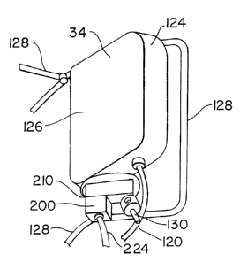
The invention further comprises a~mirror position
feedback device 200, depicted in Figs. 11 and 12.
The mirror position feedback device comprises a housing
attachable to the frame of the mirror to be rotatable with
the frame, the fixed shaft of the mirror projecting through
the housing. Referring to Figs. 11 and 12, a housing 210 is
provided for housing the feedback components. The housing
210 preferably is open at the top, and includes a plastic or
rubber seal 212 arcund the periphery of the opening. The
housing preferably is configured to attach to frame 124 of
the mirror on the bottom side, with fixed shaft 130
projecting through the housing 210. Because of this
connection, the housing 210 will rotate with mirror frame 124
about the fixed shaft 130.
The mirror position feedback device further comprises a
first pulley supported in the housing and fixedly attached to
CA 02542398 1997-12-17
-13-
the fixed shaft. As shown in Fig. 12, a first pulley 214 is
supported inside housing 210, and attached fixedly to fixed
shaft 130. When attached, first pulley 214 will not rotate
with the mirror frame 124 and housing 210. Instead, first
pulley 214 will remain fixed in position.
The invention further comprises a second pulley
supported in the housing to be rotatable with the housing and
the mirror frame. Referring to Fig. 12, a second pulley 216
is supported within the housing 210, spaced from the first
pulley 214. Second pulley 216 is supported so as to rotate
with the housing 210, as mirror frame 124 rotates.
As shown in Fig. 12, first pulley 214 has a first
selected diameter dl, and second pulley 216 has a second
selected diameter d2. First diameter dl is larger than
second diameter d2. It is preferred that dl be twice as
large as d2, for the reasons explained below.
As broadly embodied herein, the mirror position feedback
device comprises a timing belt extending between the two
pulleys. Referring to Fig. 12, a timing belt 218 extends
between first pulley 214 and second pulley 216.
The invention further comprises a potentiometer attached
to the second pulley and rotatable with the second pulley.
As shown in Fig. 12, a potentiometer 220 is fixed to second
pulley 216 via a shaft 222. The potentiometer 220 calculates
the actual amount of mirror rotation based on the amount of
rotation of second pulley 216 and the amount of movement of
timing belt 218. Potentiometer 220 can rotate a full 360°.
The preferred 2:1 ratio of the first pulley diameter dl to
the second pulley diameter d2 means that for every 2° of
rotation of second pulley 216 there will be 1° of rotation of
the mirror frame 124. The potentiometer 220 measures the
actual rotation.
A cable projects from the potentiometer and is
attachable to a remote means for remotely controlling the
mirror. As shown in Figs. 11 and 12, a cable 224 projects
CA 02542398 1997-12-17
-14-
through'a grommet 226 and attaches to,potentiometer 21U. The
other end of cable 224 is connected to processor 100. In
this way, the actual degree of mirror rotation measured by
the potentiometer 220 can be fed back,to the system, and
compared to the desired amount of mirror rotation based on
the degree of vehicle turn. The processor 100 then can
calculate whether additional mirror rotation is needed to
ensure the driver can keep the rear passenger-side corner of
the trailer 22 in his field of vision 38. The processor can
vary the mirror rotation signal sent to mirror rotation motor
122 accordingly.
The mirror position feedback device described above is
not limited for use with the mirror control assembly
described herein. A similar mirror position feedback device
can be attached to any remotely controlled vehicle mirror
assembly.
The illustrated embodiment of the present invention
operates as follows. After hooking up,trailer 22 to fifth
wheel 26, the driver manually sets support 90 to the proper
position front to rear on chassis,30, ,and tightens down bolts
46. Entering the cab, the driver energizes the system with
switch 112, sets the desired position of mirror assembly 34
with mirror positioning switch 116,, and calibrates the system
with calibration switch 118 by setting in the length of the
trailer. Typically, the mirror position is set along an axis
generally parallel with axis 32 defined by the tractor and
trailer, thereby providing the driver with a view of the rear
passenger-side corner 36 of the trailer.
After the system is energized with switch 112, the
pneumatic cylinder is activated with switch 113. Solenoid-
cperated valve 72 cpens and fluid pressure is provided via
fluid line 70 to cylinder 62. Piston arm 66 retracts,
pulling control arm 50 from disengaged position 80 to engaged
position 82, with wheel 58 in rolling contact with the
CA 02542398 1997-12-17
-15-
underside of trailer 22, along a line transverse to axis 32
defined by tractor 24 and trailer 22.
When the driver turns the vehicle, trailer 22 pivots
with respect to tractor 24 about pivot point 26. As trailer
22 pivots, control wheel 58 turns, thereby rotating cable 92.
As cable 92 rotates, the corresponding wheel rotations or
partial rotations in the form of electronic pulses are
counted by electronic counter 90. Electronic pulses then are
transmitted to processor 100.
Processor 100 calculates a degree of vehicle turn
corresponding to the counted rotations or partial rotations
of control wheel 58. Already knowing the position of mirror
assembly 36 and the length of trailer 22, processor 100
calculates a degree of mirror rotation corresponding to the
degree of vehicle turn necessary to maintain the rear
passenger corner of the trailer in the mirror's field of
vision.
Processor 100 transmits the calculated degree of mirror
rotation to servo-motor 122. Servo-motor 122 rotates mirror
face 126 in order to establish a field of vision 38(a) as
shown in Fig. 1(c). The processor 100 receives feedback from
the mirror portion feedback device in order to determine
whether the active amount of rotation corresponds to the
desired amount of rotation. If not, the processor 100 can
vary the rotation signal accordingly to obtain the desired
field of vision.
Likewise, when trailer 22 pivots back into alignment
with tractor 24 at the end of the turn, wheel 58 rolls and
cable 90 pivots in the opposite direction, resulting in a
signal to rotate the mirror back to the original position,
restoring original field of vision 38.
In this manner, the driver always can see the rear
passenger-side corner of the trailer, even during a vehicle
turn. Moreover, because regulator 86 maintains constant
pressure in cylinder 62 as the trailer moves up and down,
CA 02542398 1997-12-17
-16-
wheel 58 is kept in substantially continuous contact with the
underside of trailer 22, even on rough roads. Preferably,
when limit switch 115 is provided, the driver has continuous
positive indication at control box 110 when wheel 58 is
engaging the underside of trailer 22.
Modifications can be made to the above-described
invention. For example, the presence of ice, slush, and salt
on roads in northern climates can interfere with the
operation of control arm 50 and wheel 58. In order to
protect these components from the external environment, a
detachable or permanent protective housing 120 (depicted
broadly in Fig. 2) can be provided. The interchangeability
of signal transmitting devices between counter and processor,
and between processor and servo-motor, also has been
discussed. The system can be provided only with a servo-
motor to connect to an existing mirror assembly, or can be
provided with its own rotatable mirror assembly to mount on
the tractor. The mirror assembly itself can include a single
mirror face, or a plurality of interchangeable mirror faces
with varying optical characteristics. A separate power
source and/or pressurized fluid source can be provided, or
the system can operate from the vehicle's electrical system
and/or high pressure air system. The control panel 110 also
can be configured to enable the driver to de-energize the
automatic mirror rotation capability and take direct control
of mirror rotation.
Additionally, although the invention has been described
with respect to a passenger-side mirror on the right-hand
side of the vehicle, it can also be configured to work with
the driver's-side mirror assembly, or with a passenger-side
mirror on the left-hand side of the vehicle for use in
countries where drivers drive on the right side of the road.
Additional modifications readily will occur to those
skilled in the art. For example, in order to work with
trailers lacking a smooth underside surface, e.g,, fuel
CA 02542398 1997-12-17
-17-
tankers, car carriers, or ten and twenty-yard dirt haulers, a
flat steel plate can be mounted an the front end trailer
underside for wheel 58 to roll against. Such modifications
are well within the skill level of persons of ordinary skill.
The invention in its broader aspects, therefore, is not
limited to the specific details and embodiments described
above or shown in the drawings. Departures may be made from
such details without departing from the spirit or scope of
the invention.