Note: Descriptions are shown in the official language in which they were submitted.
CA 02542500 2006-04-11
-1-
PALLET CONTAINER
The invention relates to a pallet container for the storage and transport of
liquid
or free-flowing goods, with a thin-walled inner container of thermoplastic
material,
with ;a tubular lattice frame closely surrounding the inner plastic container
in the
form of a support jacket, and with a bottom pallet upon which the inner
plastic
container rests and with which the tubular lattice frame is securely fixed,
wherein
the inner plastic container includes for withdrawal of the liquid goods at the
lower
side, approximately in mid-section in a side wall near its bottom a blown,
calibrated tubular pipe for allowing attachment of a closeable discharge
fitting.
The invention further relates to a method of making such a pallet container.
Prior Art:
The structural configuration of such pallet containers is generally known and
its
essE:ntial components are described e.g. in the publication DE-A 34 42 701
(We).
Typiically, discharge fittings are screwed by means of a coupling nut onto an
outer thread of the outlet pipe of the inner container; known are however also
further weld-on connections for discharge fittings. A pallet container with a
discharge fitting welded directly onto the inner plastic container is known,
e.g.,
from publication DE-A 34 42 700 (We). Following the blow-molding process, a
boti:om-proximal opening is hereby provided in the inner container for
insertion of
about half of the housing of the discharge fitting and welded against the wall
of
the inner container.
Further known from the prior art are constructions with pre-fabricated
threaded
pipes or entire housings for fittings as insert into the opened blow mold with
subsequent welding with the plastic container during the blow-molding process.
These constructive variations suffer however particular drawbacks:
- The placement of the threaded pipe or housing into the blow mold is
complicated and not safe,
- welding of the insert with the inner container during blow molding process
CA 02542500 2006-04-11
-2-
is comparably undefined (no precisely controllable contact pressure),
- the through-flow opening in the inner container must be opened
subsequently through the pipe or the valve housing (e.g. drilling with
respective
contamination)
- the fitting must be completed on the container (complex);
- testing the critical component "fitting" can only be implemented on the
container itself.
- the constructions with fittings directly welded onto the container wall
represent a particular variant which does not allow use of the inner container
for
threadable fittings; this is e.g. disadvantageous for later reconditioning.
The construction, known from publication DE-A 34 42 700 with attached
connection for the discharge fitting by welding, has the following drawbacks:
- the fabrication process of the inner container is suited especially to the
type of construction of a sliding-type fitting;
- the discharge opening is incorporated subsequently into the inner
container, i.e. after the blow-molding process but before welding the
discharge
fitting,
- the region of the inner container for welding of the discharge fitting is
blown without additional aids, i.e. the thin wall thicknesses result from the
blovving process and are subject to the typical fluctuations with insufficient
reproducibility and slight stability (bending strength),
- the construction of the inner container represents a special variant which
is not applicable for fittings that can be screwed on.
Publication EP-A 0 704 385 (Prot) discloses a pallet container in which the
thrE;aded pipe is placed as pre-fabricated injection-molded part into the blow
mold and welded onto the inner plastic container, wherein the discharge
fitting is
sut>sequently screwed on by means of a coupling nut.
CA 02542500 2006-04-11
-3-
It is an object of the invention to provide a pallet container with inner
plastic
container, wherein the inner container includes a blown, calibrated tubular
pipe,
which inner plastic container allows cost-efficient manufacturing of the
connE;ction for the discharge fitting and has a particularly high load-bearing
capability (bending strength) when the discharge fitting is handled for
withdrawing goods.
The invention is characterized by a fitting with is fixedly connected to the
pipe of
the inner container by means of welding or bonding. When welded connection is
involved, various processes can be used, such as hot plate welding, laser
welding, friction welding, ultrasonic welding, or vibration welding. Hot plate
welding is used in a preferred embodiment because it is very economical while
providing easy access to the welding spot. However, also bonding by means of a
special plastics adhesive can be executed in a simple and inexpensive manner.
In contrast to the use of a coupling nut to screw the discharge fitting
connections
onto the outlet pipe, a fixed connection has the following advantages:
- Higher safety: screw connections and in particular the necessarily used
ring seals always pose a risk potential for leakage. Seals used heretofore
have
either poor sealing capabilities (slight rebound capability, cold flow, high
hardness) or no universal chemically resistance (aging, brittleness);
- Threadable connections with components of plastic (here in any event the
outlet pipe) are subject to a decrease of the tightening moment in view of the
cold
flow and thus may become leaky;
- Less costs: When fixedly connected by means of bonding or welding, the
need for the coupling nut and the ring seal is eliminated (cost savings);
- The discharge fitting is connected with the inner container preferably in
complete and pre-checked conditions.
Hereby, all types of constructions of discharge fittings, such as e.g. flap
valve,
sliding valve, ball valve, etc, may advantageously be applicable.
The connection during welding (or bonding) of fitting and inner container is
CA 02542500 2006-04-11
-4-
implemented after the blow molding process on the cooled inner plastic
container
in a separate working step under reproducible, controlled joining conditions
such
as, e.g. optimum joining time, joining temperature, joining pressure, etc.
In contrast to threads simply blown onto blow-molded parts (imprecise thread
formation, poor reproducibility), calibrated threaded pipes have good
reproducibility with exact formation of the outer thread turns (just like in
an
injectiion molding process) because the threaded pipe is held on the inside on
the
blow pin and the thread is pressed and formed on the outside by a split
threaded
calibration piece in the mold partition plane of the two-part blow mold or a
respE:ctive mold slide.
The <;omponents inner container and fitting have the following features:
- The inner container with outlet pipe attached by calibration does not
require additional finishing works of the inner container to produce the
discharge
opening; this is realized during the blowing process itself.
- Defined wall thicknesses (outer and inner contours defined by mold insert
or blow pin needle, respectively) can be realized in the outlet pipe.
- In the region of the outlet pipe, reproducibly limited, increased wall
thicknesses of the inner container can be realized, combined with gain in
strength and gain in material for the subsequent welding. The direct contact
surface for welding can be configured substantially freely and can be
optimized
for welding.
- During welding operation (or bonding operation), the calibrated threaded
pipe is held in a tongs-like fixing device having two semi-shells with
internal
thread for precise engagement in the outer thread of the outlet pipe, so that
a
high contact pressure can be applied during welding.
According to a preferred embodiment, the contact surface of the blown outlet
pipes (with outer thread) for the welding is provided with inwardly descending
slant, thereby realizing a better melting of the plastic material.
CA 02542500 2006-04-11
-5-
According to another preferred embodiment, the contact surface of the blown
outlet pipe (e.g. with flanged rim) for the welding is of flat design.
Advantageously, the outer contour of the calibrated pipe is hereby configured
such that a secure mechanical resistance is established for applying the
required
mechanical joining pressure for some welding processes (e.g. hot plate
welding).
The welded connections eliminate the ring seal and coupling nut; they
represent
a significantly lesser error source for leakage because the typically used
ring seal
ages very often or is attacked by aggressive contents (e.g. swelling,
embrittling).
According to another preferred embodiment, the contact surface of the
calibrated
outlet pipe is provided with a screw thread (universal pipe!).
During welding operation, a tool for securing the outlet pipe engages its
outer
thread so that a high joining pressure can be applied when welding the tubular
connection piece of the discharge fitting.
There thus-configured inner containers can thus be used for screwed-on or
welded-on discharge fittings. The following advantage results hereby: Weld-on
discharge fittings can be removed during reconditioning through simple
mechanical separation of the fixedly interconnected components outlet valve
and
inner container and very easily replaced for further utilization by a screwed-
on
fitting with seal and coupling nut, as practiced currently in typical pallet
containers.
The discharge fitting according to the invention of plastic is preferably
configured
with extended inlet pipe having a diameter (external e.g. 62.5 mm) which is as
closely suited as possible to the inner diameter of the outlet pipe (about
63.~i mm) so as to allow a precision fit and problem-free joining with optimum
material fusion on the welding surfaces. The outlet pipe has a length of about
20
to 50 mm, preferably about 35 mm.
they extended inlet pipe (about 20 to 40 mm, preferably about 30 mm) resists
encountered forces during mechanical loads when tested (in particular drop
test)
and application (attachment of hose connections or other couplings on the
CA 02542500 2006-04-11
-6-
discharge fitting) and relieves thereby the welded connection (high bending
strength). The configuration of the discharge fitting is designed in the area
of
welding (inlet pipe and welding flange) preferably such that the same fitting
construction with respective coupling nut and seal can find application as
threadable fitting.
The round connection piece of the discharge fitting with welding flange is
welded
to the end surface of the outlet pipe calibrated onto the inner plastic
container.
This E:nd surface of the outlet pipe is preferably slanted from outside
inwardly so
that tlhe slanted tip of the slant is initially melted during welding to
thereby
compensate tolerances of the outlet pipe as caused during blow molding. The
outer contour of the calibrated pipe with flange rim or outer thread is
configured
such that a secure mechanical resistance is established for applying the
necessary mechanical joining pressure for the welding operation.
Exemplary embodiments of the invention will now be explained and described in
more detail with reference to the drawings: It is shown in:
Fig. 1 a pallet container according to the invention,
Fig. 2 a longitudinal section of a discharge fitting,
Fig. 3 a front view of a discharge fitting,
Fig. 4 a longitudinal section A - A of the discharge fitting according to
Fig. 3,
Fig. 5a a side view of the discharge fitting before welding,
Fig. 5b a side view of the discharge fitting after welding, and
Fig. 6 a perspective view of the discharge fitting
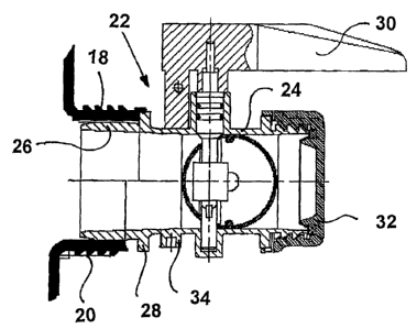
Reference character 10 designates in Fict-1 a pallet container having a
thin-walled inner container 12 of thermoplastic material, a tubular lattice
frame 14
closing surrounding the inner plastic container 12 as support jacket, and a
bottom
pallet 16 on which the inner plastic container 12 rests and with which the
tubular
CA 02542500 2006-04-11
-7-
lattice frame 14 is securely connected. The inner plastic container 12
includes for
withdrawal of liquid goods at the lower side, approximately in mid-section in
a
side wall near its bottom a blown, calibrated tubular pipe 18 with outer
thread 20
for alNowing attachment of a closeable discharge fitting 22. The pipe 18 may,
however, also be provided with a flange rim on which the discharge fitting is
secured by means of a tensioning clamp, wherein the discharge fitting may be
designed as flap valve, sliding valve, or ball valve.
The discharge fitting 22 according to the invention, shown in Fia. 22, is made
substantially of plastic and equipped according to an exemplified embodiment
with <~ flap valve closure, actuatable by a rotary grip 30, and is closed on
the
outside with a screw cap 32. The housing 24 of the discharge fitting 22 is
provided on the container side with an inlet pipe 26 which is inserted at
precision
fit in the pipe 18 up to its flange ring 28. In the lower drawing half, the
pipe 18
with outer thread 20 is slightly set back in relation to the flange ring 28
(situation
before welding), while the upper drawing half shows the pipe 18 bearing upon
the
flange rim 28 of the housing 24 of the discharge fitting 22 and securely
welded
therewith (situation after welding).
In view of a good accessibility and optimum geometries of welding spots, the
cost-efficient hot plate welding process is preferably used for the welding
operation. The discharge fitting is hereby welded onto the outlet pipe in a
complete and pre-checked state. The inner container, withdrawn from the blow
mold, does not require any refinishing of the pipe for the welding operation.
The thin-walled inner plastic container typically has a mean wall thickness of
about 3 mm, while the calibrated pipe for the discharge fitting has a wall
thickness of about 5 mm, when a configuration with an inner diameter of about
63 mm is involved. The constructive advantages of the configuration according
to
the invention are as follows: calibrated pipe with proper material thickness
for
welding and joining contour; standard pipe with outer thread for attachment of
the
respectively desired discharge fitting by screwing or welding; long inlet and
relief
pipes on the fitting with high load-bearing capability for bending stress
during
' ~ CA 02542500 2006-04-11
_8_
frequent operation of the rotary valve.
For viscous goods, pipes and discharge fittings of greater nominal width or
greater diameter of about 80 mm or even 120 mm to 150 mm may be provided.
Hereby, it is shown: the greater the diameter, the better and safer a fixed
connection (welded or bonded) of pipe and discharge fitting in comparison to a
conventional screw connection.
Fig. 3 is a front view of the discharge fitting 22, showing in particular the
front
screw cap 32 and the rotary grip 30. Fia-4 shows a longitudinal section along
the
line A-A of this discharge fitting 22. A support device 38, which is
prefabricated
as a separate injection-molded part and includes an annular outer rim and a
star-shaped or cross-shaped inner part, is inserted on the container-side
securely
into tree inlet pipe 26 of the discharge fitting 22. This cross-shaped support
device
(injec'tion-molded plastic part with fiber reinforcement) is provided to
prevent the
pipe 'I 8 from assuming an oval shape which could potentially occur as a
result of
warping or shrinkage, when the inner plastic container unevenly cools down in
this rE:gion.
Fia~5~a shows again the container pipe 18 with outer thread 20 and the
discharge
fitting 22 before insertion and before welding, whereas Fig. 5b shows the
welded
state. The inlet pipe 26 is hereby pushed into the pipe 18 up to the flange
ring 28,
and the end surface of the pipe is fixedly welded to the flange ring 28.
Refinishing
work of the welded seam is hereby not necessary.
Flq-6 shows again by way of perspective view the cross-shaped support
device 38 which is arranged in the inlet pipe 28 and extends transversely to
the
diameter and which is configured here in one piece and integrated in the
housing 22 of the discharge fitting 22.
In accordance with a particular variation, the pallet container is provided
for use
in potentially explosive zones or for use with combustible goods; in this
case, the
inner container is configured antistatically or electrically diverting on the
outside,
and i:he housing of the discharge fitting is also made of electrically
conductive
CA 02542500 2006-04-11
_g_
plastic and provided with a connection 34 for threaded attachment of a ground
cable (compare Fig. 2).
The particular advantage of this present invention resides also in the fact
that a
"normal" inner plastic container with calibrated pipe 18 and outer thread 20
is
used for welding the discharge fitting thereto; there are no modifications
necessary on the blow mold or the blown part (inner container). Thus, customer
s
desires can easily be satisfied, regardless whether a pallet container is
desired
with typical discharge fitting which is screwed on by means of a coupling nut
or is
fixedly welded in. Also, a pallet container with fixedly welded discharge
fitting can
be reused again. Reconditioning requires only a simple separation of the
welded
discharge fitting, an internal milling of the pipes, and a new fitting can be
screwed
on or welded in.
A pallet container with welded discharge fitting can be used for almost any
aggressive goods because there is no need to consider the susceptibility of
the
seal that is no longer necessary.
CA 02542500 2006-04-11
-10-
List of Reference Numerals
pallet container
12 inner container
14 tubular lattice
frame
16 bottom pallet
18 pipe (12)
outer thread
(18)
22 discharge fitting
24 housing (22)
26 inlet pipe (24)
28 flange ring (26)
rotary grip (22)
32 screw cap (22)
34 cable connection
36 safety screw
38 stabilization
cross