Language selection

Search

Patent 2542607 Summary

Third-party information liability

Some of the information on this Web page has been provided by external sources. The Government of Canada is not responsible for the accuracy, reliability or currency of the information supplied by external sources. Users wishing to rely upon this information should consult directly with the source of the information. Content provided by external sources is not subject to official languages, privacy and accessibility requirements.

Claims and Abstract availability

Any discrepancies in the text and image of the Claims and Abstract are due to differing posting times. Text of the Claims and Abstract are posted:

  • At the time the application is open to public inspection;
  • At the time of issue of the patent (grant).
(12) Patent Application: (11) CA 2542607
(54) English Title: ORNAMENTAL GARDEN HOSE STORAGE DEVICE
(54) French Title: DISPOSITIF DE RANGEMENT ORNEMENTAL POUR TUYAU D'ARROSAGE DE JARDIN
Status: Deemed Abandoned and Beyond the Period of Reinstatement - Pending Response to Notice of Disregarded Communication
Bibliographic Data
(51) International Patent Classification (IPC):
  • B65H 75/40 (2006.01)
  • B65H 75/44 (2006.01)
(72) Inventors :
  • HIGGINS, CHRISTOPHER LYNDON (Australia)
(73) Owners :
  • ABACUS (C.I.) LIMITED AS TRUSTEE OF THE BAYVIEW TRUST
(71) Applicants :
  • ABACUS (C.I.) LIMITED AS TRUSTEE OF THE BAYVIEW TRUST (United Kingdom)
(74) Agent: BORDEN LADNER GERVAIS LLP
(74) Associate agent:
(45) Issued:
(86) PCT Filing Date: 2004-10-13
(87) Open to Public Inspection: 2005-04-21
Availability of licence: N/A
Dedicated to the Public: N/A
(25) Language of filing: English

Patent Cooperation Treaty (PCT): Yes
(86) PCT Filing Number: PCT/AU2004/001395
(87) International Publication Number: WO 2005035417
(85) National Entry: 2006-04-13

(30) Application Priority Data:
Application No. Country/Territory Date
2003905583 (Australia) 2003-10-13

Abstracts

English Abstract


A functional garden device includes an upper portion (10) and a lower portion
(60). Lower portion (60) includes a retractable hose reel (80) for garden hose
(90) which passes through orifice (63) in wall (65). Upper portion (10) has a
separate, unrelated function to the hose storage portion (60) and may form
part of a fountain, pond, statue, refrigerated storage area or a planting
container.


French Abstract

Cette invention concerne un dispositif de jardin fonctionnel comprenant une partie supérieure (10) et une partie inférieure (60). La partie inférieure (60) comprend une enrouleur rétractable (80) pour un tuyau de jardin (90) qui traverse un orifice (63) dans une paroi (65). La partie supérieure (10) a une fonction distincte et sans rapport avec la partie de rangement pour tuyau (60) et peut faire partie d'une fontaine, d'un bassin, d'une statue, d'une zone de rangement réfrigérée ou d'un bac à plantes.

Claims

Note: Claims are shown in the official language in which they were submitted.

CLAIMS
1. a hose storage device with a retractable hose reel contained inside a
portion of
a functional whole item said functional whole item having a functional use 1
which use is other than the hose storage device function 2. The said
functional
whole item may be one discrete item carrying out functional use1 whilst
containing a hose storage device function 2.

Description

Note: Descriptions are shown in the official language in which they were submitted.


CA 02542607 2006-04-13
WO 2005/035417 PCT/AU2004/001395
ORNAMENTAL GARDEN HOSE STORAGE DEVICE
FIELD OF THE INVENTION
The present invention relates to storage of items within functional garden
items and more particularly to containers for storage and access to hoses or
hose- reels
where the hose storage container is or forms part of a whole item which item
has a
function separate from and/or unrelated to the function of a hose storage
container
BACKGROUND TO THE INVENTION
Any discussion of the prior art throughout the specification should in no way
l0 be considered as an admission that such prior art is widely known or forms
part of
common general knowledge in the field.
Kownacki in US Patent 5988207 and Macey Smith in US Patent 6467499
teach us the use of a decorative storage devices for a garden hose.
One problem that exists with prior art is that the storage device is often
located
far from the desired point of use such that the hose is too short and/or the
hose-reel
must be very large to accommodate sufficient hose to accomplish the desired
task.
Especially in larger gardens it is not desirable to have unsightly hose-reel
storage
devices located in the garden area .
Another problem is that expensive materials such as plastic are used to form
at
least a portion of hose-reel cover.
A further problem is that in situations such as apartments where space on any
balcony or outside area is restricted it is desirable to limit the number of
items in an
area.
It is an object of the present invention to overcome or ameliorate at least
one
of the disadvantages of the prior art, or to provide a useful alternative.

CA 02542607 2006-04-13
WO 2005/035417 PCT/AU2004/001395
SUMMARY OF THE INVENTION
One aspect of the present invention is directed to a hose storage device with
a
retractable hose reel contained inside a portion of a functional whole item
said
functional whole item having a functional use 1 which use is other than the
hose
storage device function 2. The said functional whole item may be one discrete
item
carrying out functional usel whilst containing a hose storage device function
2 .
A portion, preferably the upper portion of the device may be used to contain
or form
1o part of any useful garden item. For example but not limited to:-
to contain or function as a pot containing plants and/or
to contain or function as fountain or pond and/or
to contain or function as a base for or form part of statuary or statues
and/or
to contain or function as or form part of illumination means and/or
to contain or function as a device or storage area which may be refrigerated
or heated
The preferred , but not limiting, form of the invention is an urn or pot of
appropriate
diameter and height to contain a retractable hose reel. The upper portion of
the
preferred form is watertight in the case where it forms part of a fountain or
may have
2o strategically placed drain holes to direct drainage water away from the
roots of plants
in such a way so as not to flow into the lower portion and damage the garden
hose and
retractable hose reel mechanism.
BRIEF DESCRIPTION OF DRAWINGS
Preferred embodiments of the invention will now be described, by way of
example only, with reference to the accompanying drawings in which:
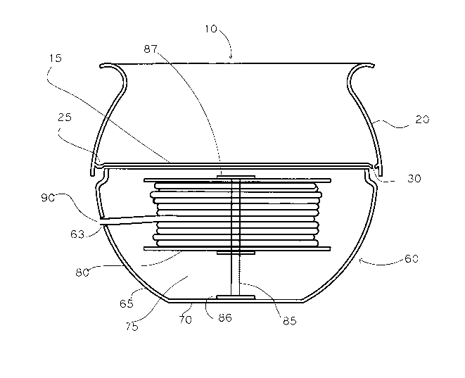
Fig. 1 depicts a sectional view of an urn or pot containing a retractable hose
storage device. The said urn may be formed from any suitable material but is
preferably formed using fibre-glass reinforced concrete which is suitable to
produce
3o inexpensive thin walled lightweight products suitable for mass production
methods.
The device may be described as follows:-

CA 02542607 2006-04-13
WO 2005/035417 PCT/AU2004/001395
A device designed to form any functional item appropriate for a garden or
conservatory or outdoor area and which device contains a concealed retractable
hose
storage device

CA 02542607 2006-04-13
WO 2005/035417 PCT/AU2004/001395
DETAILED DESCRIPTION OF PREFERRED EMBODIMENTS
The preferred , but not limiting, form of the invention is an urn or pot of
appropriate
diameter and height to contain a retractable hose reel. The upper portion of
the
preferred form is watertight in the case where it forms part of a fountain or
may have
1o strategically placed drain holes to direct drainage water away from the
roots of plants
in such a way so as not to flow into the lower portion and damage the garden
hose and
retractable hose reel mechanism.
Fig. 1 which shows a sectional view of an urn consisting of a container upper
portion 10 and a container lower portion 60 upon which the upper portion
rests.
The container upper portion 10 has a base 15 and sides 20 which are contiguous
and
form a water tight vessel. The base 15 has a channel 25 around its outer
perimeter
adjoining the sides 20. The purpose of the channel 25 is so that when the
container
2o upper portion is to be used as plant containing means then the said channel
provides a
means of collecting and directing water which falls upon the base 15 to holes
30
placed strategically at one or more locations in the base of the said channel
so that
water may drain from the container upper portion without flooding the
container lower
portion.
An additional one of the holes 30 may be used to provide access for water from
a
separate irrigation water supply (not shown) to provide water for any plants
contained
in the said container upper portion.
The container lower portion 60 consists sides 65 and a base 70 and, one of
said sides
has an orifice 63 of appropriate shape and dimension to permit the hose 90 to
be
withdrawn from the hose reel when required said orifice may be formed (not
shown)
as part of a recess in the said side such that any "clip - on " hose fitting
is recessed

CA 02542607 2006-04-13
WO 2005/035417 PCT/AU2004/001395
into the said recess thereby tending to hide said hose fitting. Said orifice
63 may
instead be a vertical slot
The said container lower portion 60 contains the retractable hose reel 80 and
s supporting axle 85 on axle end locating/and or fastening means 86 and 87
The side 65 or base 70 has one or more holes and/or channels to permit
connection of
supply means such as water supply to the hose on the hose reel and/or
electricity
supply to operate lighting andfor pumps and/or valves to control water. Said
hose
l0 fitting andlor connecting hose and/or electricity supply cable may be
located within an
appropriately formed recess or channel ( not shown) in the side 65 and/or base
70 of
the said container lower portion 60. Such recess and/or channel will be formed
to hide
or disguise the said supply entry and in the case of a channel in the base70
will permit
supply to enter into the container lower portion 60 without the hose or pipe
or cable
15 being crushed by the weight of the device. Said supply may have one or more
switches andlor valves to constrict and/or adjust and/or shut-off supply of
water
and/or electricity.
The said container lower portion contains a space 75 between the lower edge of
the
20 hose-reel 80 and the base 70 such space being provided to allow the fitting
of a
counterweight such as sand-bags to steady the device against the force exerted
when
pulling hose from the reel. Alternatively, the device may be steadied by
fixing the
base 70 by known fastening means into the desired position onto the surface
upon
which it stands.
The said container lower portion 60 may also be constructed with a cover piece
62
(not shown ) to which is connected by known means axle end locating/and or
fastening means 87 and said lower portion 60 may also have formed on the inner
surface of base 70 locating or housing means (not shown) such as lugs or
ridges
forming an annular locating means to locate annular axle end locating/and or
fastening
means 86 so that said axle end locating/and or fastening means 86 is
restrained from
moving when the hose-reel is under stress of extraction or retraction of the
hose.

CA 02542607 2006-04-13
WO 2005/035417 PCT/AU2004/001395
In another example (not shown) , the base 15 may be formed to create a
downwards
slope inwards from the sides 20 to a low point hole in the centre above the
axle 85 and
axle 85 may be hollow so that drainage water can pass through the hollow axle
or a
drainage tube inside the hollow axle and pass out of the urn without staining
the sides
65 of lower portion 60 below holes 30.

Representative Drawing
A single figure which represents the drawing illustrating the invention.
Administrative Status

2024-08-01:As part of the Next Generation Patents (NGP) transition, the Canadian Patents Database (CPD) now contains a more detailed Event History, which replicates the Event Log of our new back-office solution.

Please note that "Inactive:" events refers to events no longer in use in our new back-office solution.

For a clearer understanding of the status of the application/patent presented on this page, the site Disclaimer , as well as the definitions for Patent , Event History , Maintenance Fee  and Payment History  should be consulted.

Event History

Description Date
Application Not Reinstated by Deadline 2009-10-13
Time Limit for Reversal Expired 2009-10-13
Deemed Abandoned - Failure to Respond to Maintenance Fee Notice 2008-10-14
Inactive: IPRP received 2007-07-24
Inactive: Cover page published 2006-06-23
Letter Sent 2006-06-20
Inactive: Notice - National entry - No RFE 2006-06-16
Application Received - PCT 2006-05-15
Inactive: Correspondence - Formalities 2006-04-28
National Entry Requirements Determined Compliant 2006-04-13
Application Published (Open to Public Inspection) 2005-04-21

Abandonment History

Abandonment Date Reason Reinstatement Date
2008-10-14

Maintenance Fee

The last payment was received on 2007-10-05

Note : If the full payment has not been received on or before the date indicated, a further fee may be required which may be one of the following

  • the reinstatement fee;
  • the late payment fee; or
  • additional fee to reverse deemed expiry.

Please refer to the CIPO Patent Fees web page to see all current fee amounts.

Fee History

Fee Type Anniversary Year Due Date Paid Date
Basic national fee - standard 2006-04-13
Registration of a document 2006-04-13
MF (application, 2nd anniv.) - standard 02 2006-10-13 2006-07-26
MF (application, 3rd anniv.) - standard 03 2007-10-15 2007-10-05
Owners on Record

Note: Records showing the ownership history in alphabetical order.

Current Owners on Record
ABACUS (C.I.) LIMITED AS TRUSTEE OF THE BAYVIEW TRUST
Past Owners on Record
CHRISTOPHER LYNDON HIGGINS
Past Owners that do not appear in the "Owners on Record" listing will appear in other documentation within the application.
Documents

To view selected files, please enter reCAPTCHA code :


To view images, click a link in the Document Description column. To download the documents, select one or more checkboxes in the first column and then click the "Download Selected in PDF format (Zip Archive)" or the "Download Selected as Single PDF" button.

List of published and non-published patent-specific documents on the CPD .

If you have any difficulty accessing content, you can call the Client Service Centre at 1-866-997-1936 or send them an e-mail at CIPO Client Service Centre.


Document
Description 
Date
(yyyy-mm-dd) 
Number of pages   Size of Image (KB) 
Claims 2006-04-13 1 10
Abstract 2006-04-13 2 61
Drawings 2006-04-13 1 17
Description 2006-04-13 6 186
Representative drawing 2006-04-13 1 12
Cover Page 2006-06-23 1 36
Description 2006-04-14 5 261
Claims 2006-04-14 3 104
Reminder of maintenance fee due 2006-06-19 1 110
Notice of National Entry 2006-06-16 1 192
Courtesy - Certificate of registration (related document(s)) 2006-06-20 1 105
Courtesy - Abandonment Letter (Maintenance Fee) 2008-12-09 1 174
Reminder - Request for Examination 2009-06-16 1 116
Correspondence 2006-04-28 1 31
PCT 2006-04-13 5 158
PCT 2006-04-13 1 42
PCT 2006-04-14 11 523