Sélection de la langue

Search

Sommaire du brevet 2542607 

Énoncé de désistement de responsabilité concernant l'information provenant de tiers

Une partie des informations de ce site Web a été fournie par des sources externes. Le gouvernement du Canada n'assume aucune responsabilité concernant la précision, l'actualité ou la fiabilité des informations fournies par les sources externes. Les utilisateurs qui désirent employer cette information devraient consulter directement la source des informations. Le contenu fourni par les sources externes n'est pas assujetti aux exigences sur les langues officielles, la protection des renseignements personnels et l'accessibilité.

Disponibilité de l'Abrégé et des Revendications

L'apparition de différences dans le texte et l'image des Revendications et de l'Abrégé dépend du moment auquel le document est publié. Les textes des Revendications et de l'Abrégé sont affichés :

  • lorsque la demande peut être examinée par le public;
  • lorsque le brevet est émis (délivrance).
(12) Demande de brevet: (11) CA 2542607
(54) Titre français: DISPOSITIF DE RANGEMENT ORNEMENTAL POUR TUYAU D'ARROSAGE DE JARDIN
(54) Titre anglais: ORNAMENTAL GARDEN HOSE STORAGE DEVICE
Statut: Réputée abandonnée et au-delà du délai pour le rétablissement - en attente de la réponse à l’avis de communication rejetée
Données bibliographiques
(51) Classification internationale des brevets (CIB):
  • B65H 75/40 (2006.01)
  • B65H 75/44 (2006.01)
(72) Inventeurs :
  • HIGGINS, CHRISTOPHER LYNDON (Australie)
(73) Titulaires :
  • ABACUS (C.I.) LIMITED AS TRUSTEE OF THE BAYVIEW TRUST
(71) Demandeurs :
  • ABACUS (C.I.) LIMITED AS TRUSTEE OF THE BAYVIEW TRUST (Royaume-Uni)
(74) Agent: BORDEN LADNER GERVAIS LLP
(74) Co-agent:
(45) Délivré:
(86) Date de dépôt PCT: 2004-10-13
(87) Mise à la disponibilité du public: 2005-04-21
Licence disponible: S.O.
Cédé au domaine public: S.O.
(25) Langue des documents déposés: Anglais

Traité de coopération en matière de brevets (PCT): Oui
(86) Numéro de la demande PCT: PCT/AU2004/001395
(87) Numéro de publication internationale PCT: WO 2005035417
(85) Entrée nationale: 2006-04-13

(30) Données de priorité de la demande:
Numéro de la demande Pays / territoire Date
2003905583 (Australie) 2003-10-13

Abrégés

Abrégé français

Cette invention concerne un dispositif de jardin fonctionnel comprenant une partie supérieure (10) et une partie inférieure (60). La partie inférieure (60) comprend une enrouleur rétractable (80) pour un tuyau de jardin (90) qui traverse un orifice (63) dans une paroi (65). La partie supérieure (10) a une fonction distincte et sans rapport avec la partie de rangement pour tuyau (60) et peut faire partie d'une fontaine, d'un bassin, d'une statue, d'une zone de rangement réfrigérée ou d'un bac à plantes.


Abrégé anglais


A functional garden device includes an upper portion (10) and a lower portion
(60). Lower portion (60) includes a retractable hose reel (80) for garden hose
(90) which passes through orifice (63) in wall (65). Upper portion (10) has a
separate, unrelated function to the hose storage portion (60) and may form
part of a fountain, pond, statue, refrigerated storage area or a planting
container.

Revendications

Note : Les revendications sont présentées dans la langue officielle dans laquelle elles ont été soumises.


CLAIMS
1. a hose storage device with a retractable hose reel contained inside a
portion of
a functional whole item said functional whole item having a functional use 1
which use is other than the hose storage device function 2. The said
functional
whole item may be one discrete item carrying out functional use1 whilst
containing a hose storage device function 2.

Description

Note : Les descriptions sont présentées dans la langue officielle dans laquelle elles ont été soumises.

CA 02542607 2006-04-13
WO 2005/035417 PCT/AU2004/001395
ORNAMENTAL GARDEN HOSE STORAGE DEVICE
FIELD OF THE INVENTION
The present invention relates to storage of items within functional garden
items and more particularly to containers for storage and access to hoses or
hose- reels
where the hose storage container is or forms part of a whole item which item
has a
function separate from and/or unrelated to the function of a hose storage
container
BACKGROUND TO THE INVENTION
Any discussion of the prior art throughout the specification should in no way
l0 be considered as an admission that such prior art is widely known or forms
part of
common general knowledge in the field.
Kownacki in US Patent 5988207 and Macey Smith in US Patent 6467499
teach us the use of a decorative storage devices for a garden hose.
One problem that exists with prior art is that the storage device is often
located
far from the desired point of use such that the hose is too short and/or the
hose-reel
must be very large to accommodate sufficient hose to accomplish the desired
task.
Especially in larger gardens it is not desirable to have unsightly hose-reel
storage
devices located in the garden area .
Another problem is that expensive materials such as plastic are used to form
at
least a portion of hose-reel cover.
A further problem is that in situations such as apartments where space on any
balcony or outside area is restricted it is desirable to limit the number of
items in an
area.
It is an object of the present invention to overcome or ameliorate at least
one
of the disadvantages of the prior art, or to provide a useful alternative.

CA 02542607 2006-04-13
WO 2005/035417 PCT/AU2004/001395
SUMMARY OF THE INVENTION
One aspect of the present invention is directed to a hose storage device with
a
retractable hose reel contained inside a portion of a functional whole item
said
functional whole item having a functional use 1 which use is other than the
hose
storage device function 2. The said functional whole item may be one discrete
item
carrying out functional usel whilst containing a hose storage device function
2 .
A portion, preferably the upper portion of the device may be used to contain
or form
1o part of any useful garden item. For example but not limited to:-
to contain or function as a pot containing plants and/or
to contain or function as fountain or pond and/or
to contain or function as a base for or form part of statuary or statues
and/or
to contain or function as or form part of illumination means and/or
to contain or function as a device or storage area which may be refrigerated
or heated
The preferred , but not limiting, form of the invention is an urn or pot of
appropriate
diameter and height to contain a retractable hose reel. The upper portion of
the
preferred form is watertight in the case where it forms part of a fountain or
may have
2o strategically placed drain holes to direct drainage water away from the
roots of plants
in such a way so as not to flow into the lower portion and damage the garden
hose and
retractable hose reel mechanism.
BRIEF DESCRIPTION OF DRAWINGS
Preferred embodiments of the invention will now be described, by way of
example only, with reference to the accompanying drawings in which:
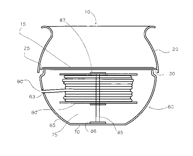
Fig. 1 depicts a sectional view of an urn or pot containing a retractable hose
storage device. The said urn may be formed from any suitable material but is
preferably formed using fibre-glass reinforced concrete which is suitable to
produce
3o inexpensive thin walled lightweight products suitable for mass production
methods.
The device may be described as follows:-

CA 02542607 2006-04-13
WO 2005/035417 PCT/AU2004/001395
A device designed to form any functional item appropriate for a garden or
conservatory or outdoor area and which device contains a concealed retractable
hose
storage device

CA 02542607 2006-04-13
WO 2005/035417 PCT/AU2004/001395
DETAILED DESCRIPTION OF PREFERRED EMBODIMENTS
The preferred , but not limiting, form of the invention is an urn or pot of
appropriate
diameter and height to contain a retractable hose reel. The upper portion of
the
preferred form is watertight in the case where it forms part of a fountain or
may have
1o strategically placed drain holes to direct drainage water away from the
roots of plants
in such a way so as not to flow into the lower portion and damage the garden
hose and
retractable hose reel mechanism.
Fig. 1 which shows a sectional view of an urn consisting of a container upper
portion 10 and a container lower portion 60 upon which the upper portion
rests.
The container upper portion 10 has a base 15 and sides 20 which are contiguous
and
form a water tight vessel. The base 15 has a channel 25 around its outer
perimeter
adjoining the sides 20. The purpose of the channel 25 is so that when the
container
2o upper portion is to be used as plant containing means then the said channel
provides a
means of collecting and directing water which falls upon the base 15 to holes
30
placed strategically at one or more locations in the base of the said channel
so that
water may drain from the container upper portion without flooding the
container lower
portion.
An additional one of the holes 30 may be used to provide access for water from
a
separate irrigation water supply (not shown) to provide water for any plants
contained
in the said container upper portion.
The container lower portion 60 consists sides 65 and a base 70 and, one of
said sides
has an orifice 63 of appropriate shape and dimension to permit the hose 90 to
be
withdrawn from the hose reel when required said orifice may be formed (not
shown)
as part of a recess in the said side such that any "clip - on " hose fitting
is recessed

CA 02542607 2006-04-13
WO 2005/035417 PCT/AU2004/001395
into the said recess thereby tending to hide said hose fitting. Said orifice
63 may
instead be a vertical slot
The said container lower portion 60 contains the retractable hose reel 80 and
s supporting axle 85 on axle end locating/and or fastening means 86 and 87
The side 65 or base 70 has one or more holes and/or channels to permit
connection of
supply means such as water supply to the hose on the hose reel and/or
electricity
supply to operate lighting andfor pumps and/or valves to control water. Said
hose
l0 fitting andlor connecting hose and/or electricity supply cable may be
located within an
appropriately formed recess or channel ( not shown) in the side 65 and/or base
70 of
the said container lower portion 60. Such recess and/or channel will be formed
to hide
or disguise the said supply entry and in the case of a channel in the base70
will permit
supply to enter into the container lower portion 60 without the hose or pipe
or cable
15 being crushed by the weight of the device. Said supply may have one or more
switches andlor valves to constrict and/or adjust and/or shut-off supply of
water
and/or electricity.
The said container lower portion contains a space 75 between the lower edge of
the
20 hose-reel 80 and the base 70 such space being provided to allow the fitting
of a
counterweight such as sand-bags to steady the device against the force exerted
when
pulling hose from the reel. Alternatively, the device may be steadied by
fixing the
base 70 by known fastening means into the desired position onto the surface
upon
which it stands.
The said container lower portion 60 may also be constructed with a cover piece
62
(not shown ) to which is connected by known means axle end locating/and or
fastening means 87 and said lower portion 60 may also have formed on the inner
surface of base 70 locating or housing means (not shown) such as lugs or
ridges
forming an annular locating means to locate annular axle end locating/and or
fastening
means 86 so that said axle end locating/and or fastening means 86 is
restrained from
moving when the hose-reel is under stress of extraction or retraction of the
hose.

CA 02542607 2006-04-13
WO 2005/035417 PCT/AU2004/001395
In another example (not shown) , the base 15 may be formed to create a
downwards
slope inwards from the sides 20 to a low point hole in the centre above the
axle 85 and
axle 85 may be hollow so that drainage water can pass through the hollow axle
or a
drainage tube inside the hollow axle and pass out of the urn without staining
the sides
65 of lower portion 60 below holes 30.

Dessin représentatif
Une figure unique qui représente un dessin illustrant l'invention.
États administratifs

2024-08-01 : Dans le cadre de la transition vers les Brevets de nouvelle génération (BNG), la base de données sur les brevets canadiens (BDBC) contient désormais un Historique d'événement plus détaillé, qui reproduit le Journal des événements de notre nouvelle solution interne.

Veuillez noter que les événements débutant par « Inactive : » se réfèrent à des événements qui ne sont plus utilisés dans notre nouvelle solution interne.

Pour une meilleure compréhension de l'état de la demande ou brevet qui figure sur cette page, la rubrique Mise en garde , et les descriptions de Brevet , Historique d'événement , Taxes périodiques et Historique des paiements devraient être consultées.

Historique d'événement

Description Date
Demande non rétablie avant l'échéance 2009-10-13
Le délai pour l'annulation est expiré 2009-10-13
Réputée abandonnée - omission de répondre à un avis sur les taxes pour le maintien en état 2008-10-14
Inactive : IPRP reçu 2007-07-24
Inactive : Page couverture publiée 2006-06-23
Lettre envoyée 2006-06-20
Inactive : Notice - Entrée phase nat. - Pas de RE 2006-06-16
Demande reçue - PCT 2006-05-15
Inactive : Correspondance - Formalités 2006-04-28
Exigences pour l'entrée dans la phase nationale - jugée conforme 2006-04-13
Demande publiée (accessible au public) 2005-04-21

Historique d'abandonnement

Date d'abandonnement Raison Date de rétablissement
2008-10-14

Taxes périodiques

Le dernier paiement a été reçu le 2007-10-05

Avis : Si le paiement en totalité n'a pas été reçu au plus tard à la date indiquée, une taxe supplémentaire peut être imposée, soit une des taxes suivantes :

  • taxe de rétablissement ;
  • taxe pour paiement en souffrance ; ou
  • taxe additionnelle pour le renversement d'une péremption réputée.

Veuillez vous référer à la page web des taxes sur les brevets de l'OPIC pour voir tous les montants actuels des taxes.

Historique des taxes

Type de taxes Anniversaire Échéance Date payée
Taxe nationale de base - générale 2006-04-13
Enregistrement d'un document 2006-04-13
TM (demande, 2e anniv.) - générale 02 2006-10-13 2006-07-26
TM (demande, 3e anniv.) - générale 03 2007-10-15 2007-10-05
Titulaires au dossier

Les titulaires actuels et antérieures au dossier sont affichés en ordre alphabétique.

Titulaires actuels au dossier
ABACUS (C.I.) LIMITED AS TRUSTEE OF THE BAYVIEW TRUST
Titulaires antérieures au dossier
CHRISTOPHER LYNDON HIGGINS
Les propriétaires antérieurs qui ne figurent pas dans la liste des « Propriétaires au dossier » apparaîtront dans d'autres documents au dossier.
Documents

Pour visionner les fichiers sélectionnés, entrer le code reCAPTCHA :


Pour visualiser une image, cliquer sur un lien dans la colonne description du document. Pour télécharger l'image (les images), cliquer l'une ou plusieurs cases à cocher dans la première colonne et ensuite cliquer sur le bouton "Télécharger sélection en format PDF (archive Zip)" ou le bouton "Télécharger sélection (en un fichier PDF fusionné)".

Liste des documents de brevet publiés et non publiés sur la BDBC .

Si vous avez des difficultés à accéder au contenu, veuillez communiquer avec le Centre de services à la clientèle au 1-866-997-1936, ou envoyer un courriel au Centre de service à la clientèle de l'OPIC.


Description du
Document 
Date
(aaaa-mm-jj) 
Nombre de pages   Taille de l'image (Ko) 
Revendications 2006-04-13 1 10
Abrégé 2006-04-13 2 61
Dessins 2006-04-13 1 17
Description 2006-04-13 6 186
Dessin représentatif 2006-04-13 1 12
Page couverture 2006-06-23 1 36
Description 2006-04-14 5 261
Revendications 2006-04-14 3 104
Rappel de taxe de maintien due 2006-06-19 1 110
Avis d'entree dans la phase nationale 2006-06-16 1 192
Courtoisie - Certificat d'enregistrement (document(s) connexe(s)) 2006-06-20 1 105
Courtoisie - Lettre d'abandon (taxe de maintien en état) 2008-12-09 1 174
Rappel - requête d'examen 2009-06-16 1 116
Correspondance 2006-04-28 1 31
PCT 2006-04-13 5 158
PCT 2006-04-13 1 42
PCT 2006-04-14 11 523