Language selection

Search

Patent 2542676 Summary

Third-party information liability

Some of the information on this Web page has been provided by external sources. The Government of Canada is not responsible for the accuracy, reliability or currency of the information supplied by external sources. Users wishing to rely upon this information should consult directly with the source of the information. Content provided by external sources is not subject to official languages, privacy and accessibility requirements.

Claims and Abstract availability

Any discrepancies in the text and image of the Claims and Abstract are due to differing posting times. Text of the Claims and Abstract are posted:

  • At the time the application is open to public inspection;
  • At the time of issue of the patent (grant).
(12) Patent: (11) CA 2542676
(54) English Title: GASIFICATION BOILER FOR SOLID FUELS, IN PARTICULAR FOR BALES OF STRAW, WITH OPTIMISED EXHAUST GAS VALUES
(54) French Title: CHAUDIERE A GAZEIFICATION POUR COMBUSTIBLES SOLIDES, EN PARTICULIER DES BOTTES DE PAILLE, PRESENTANT DES VALEURS D'ECHAPPEMENT OPTIMISEES
Status: Deemed expired
Bibliographic Data
(51) International Patent Classification (IPC):
  • F23G 7/06 (2006.01)
  • F23G 5/027 (2006.01)
(72) Inventors :
  • HERLT, CHRISTIAN (Germany)
(73) Owners :
  • HERLT, CHRISTIAN (Germany)
(71) Applicants :
  • HERLT, CHRISTIAN (Germany)
(74) Agent: BORDEN LADNER GERVAIS LLP
(74) Associate agent:
(45) Issued: 2010-12-07
(86) PCT Filing Date: 2004-10-07
(87) Open to Public Inspection: 2005-05-06
Examination requested: 2007-10-18
Availability of licence: N/A
(25) Language of filing: English

Patent Cooperation Treaty (PCT): Yes
(86) PCT Filing Number: PCT/DE2004/002240
(87) International Publication Number: WO2005/040680
(85) National Entry: 2006-04-13

(30) Application Priority Data:
Application No. Country/Territory Date
103 49 365.4 Germany 2003-10-16

Abstracts

English Abstract


The invention relates to a gasification boiler for the combustion of solid
fuels, in
particular bales of straw, for heating purposes and for the production of hot
water. The
inventive boiler is characterised by optimal combustion and ash separation.
The aim of
the invention is to carry out the combustion of small particles in the most
complete
manner possible and to achieve an almost total separation of the ashes from
the
combustion gas upstream of the heat exchangers. To achieve this, according to
the first
feature of claim 1, the combustion and gasification chamber comprises lateral
depressions that are configured next to the central grating and combustion
chamber.
Coarse particles collect in said depressions, leaving the fine particles to be
carried with
the combustion gas into the combustion chamber. According to the second
feature of
said claim, a cylindrical combustion chamber, configured as an additional
component, is
connected to the outlet of the combustion chamber. Said secondary combustion
chamber significantly increases the combustion time, allowing small particles
and
partially oxidised gases to burn completely. According to the third feature, a
cylindrical
ash separator, configured as an additional component, is connected to the
combustion
chamber.


French Abstract

L'invention concerne une chaudière à gazéification destinée à la combustion de combustibles solides, en particulier des bottes de paille, à des fins de chauffage et de production d'eau chaude. L'invention est caractérisée par une combustion et une séparation des cendres optimales. L'objectif de l'invention est d'obtenir une combustion la plus complète possible des petites particules également et une séparation quasi totale des cendres présentes dans le gaz de combustion en amont des échangeurs de chaleur. A cet effet, d'après le premier point de la revendication n·1, la chambre à combustible et de gazéification comporte des cavités ménagées latéralement à côté de la grille centrale et de l'espace de combustion. Les grosses particules sont collectées dans ces cavités, tandis que les particules fines sont acheminées avec le gaz de combustion dans l'espace de combustion. D'après le deuxième point, une chambre de combustion cylindrique se présentant sous la forme d'une unité modulaire additionnelle est rattachée à la sortie de l'espace de combustion. Cette chambre de postcombustion permet de prolonger considérablement le temps de combustion, les petites particules et les gaz partiellement oxydés pouvant ainsi être totalement brûlés. D'après le troisième point, un séparateur de cendres cylindrique se présentant sous la forme d'une unité modulaire additionnelle est rattaché à la chambre de combustion.

Claims

Note: Claims are shown in the official language in which they were submitted.


-8-

CLAIMS:


1. A gasification boiler for solid fuels with optimized exhaust
gas values and burn-up at the bottom, comprising a fuel and
gasification space which can be closed by means of a filling door
and has air feeds, a grating arranged at the bottom, a combustion
space situated below it, and ash separator, heat exchange surfaces
and fan arranged behind it in terms of flow,
wherein the fuel and gasification space has depressions for
collecting ash laterally next to the centrally arranged grating
and the combustion space,
wherein a cylindrical combustion chamber designed as an
additional constructional unit is connected to the outlet of the
combustion space, and
wherein a cylindrical ash separator which is designed as an
additional constructional unit and is connected to a known heat
exchanger is connected to the combustion chamber.

2. The gasification boiler as claimed in claim 1, wherein the
lower, lateral depressions of the fuel and gasification space are
of half-shell-shaped design and run parallel to the combustion
space and the latter is in each case assigned a small door for the
removal of ash.

3. The gasification boiler as claimed in claim 1 or 2, wherein
the cylindrical combustion chamber is connected at the bottom
tangentially to the outlet of the combustion space, so that the
combustion gas rises therein in a swirling manner and in that the
combustion chamber is adapted to be closed at the top by a cover.
4. The gasification boiler as claimed in any one of claims 1 to
3, wherein the cylindrical ash separator is connected at the top
tangentially to the outlet of the combustion chamber, and a flue
pipe with the opening approximately halfway up is arranged
centrally relative to the ash separator.


-9-


5. The gasification boiler as claimed in claim 4, wherein a
circular baffle plate is fitted below the opening of the flue pipe
in such a manner that an annular opening for the depositing of ash
remains from the outer wall, and in that the ash separator is
adapted to be closed at the top by a cover.

6. The gasification boiler as claimed in any one of claims 1 to
5, wherein the cylindrical combustion chamber, the cylindrical ash
separator and the heat exchanger are connected in a framework to
form a constructional unit.

7. The gasification boiler as claimed in any one of claims 1 to
6, wherein the said fuels are bales of straw.

Description

Note: Descriptions are shown in the official language in which they were submitted.


CA 02542676 2006-04-13
- 1 -

Gasification boiler for solid fuels, in particular for
bales of straw, with optimized exhaust gas values
Description
The invention relates to a gasification boiler for the
combustion of solid fuels, especially bales of straw,
for heating purposes and for the production of hot
water. The invention is distinguished by optimum
combustion and ash separation. The prescribed exhaust
gas values are therefore reliably kept to.

Prior art

The principle of fuel gasification in a furnace space
and of aftercombustion in a separate combustion space
has substantial advantages for fuels in lump form.
These are primarily a substantial, clean combustion,
and therefore low environmental pollution and a high
energy yield. The known designs comprise a closed fuel-
filling space with filling door, a lower burn-up and
gasification zone, a lower grating and combustion
nozzle with a combustion space, air feeds, heat
exchanger and ash separator situated under or behind
it. A heating boiler of this type for combustion of
solid material is described, for example, in
DE-A 34 08 602 and DE-C 37 18 022. To improve the
combustion, special air and combustion gas guides have
been proposed. According to DE-A 3411822, the filling
shaft is in the form of a double cone with gas outlet
openings and an annular combustion duct in the
extension. A uniform burn-up and simple construction
are intended to be realized therewith. DE-C 3617146
illustrates a special air feed for the primary air in
order to achieve a good combustion gas/air mixture. The
fan is mounted on the filling door and feeds external
air into three levels of the fuel shaft. The solution
in DE-C 3718022 contains two air feed levels in the


CA 02542676 2010-01-08
- 2 -

fuel shaft and one to the combustion space. With the recycling of
exhaust gas, particularly good gasification is intended to be
achieved.

The fuel comprising bales of straw causes particular requirements.
There is the problem of uniform gasification which is obstructed
by carbonization of the outer layers. A high content of
uncombusted small constituents and a low ash melting point have an
unfavourable effect on the exhaust gas values and dirty the
exchange surfaces (DE-A 41 34 754).

Summary of the Invention

It is desirable to carry out the combustion even of small
particles as completely as possible and to virtually completely
separate the ash from the combustion gas upstream of the heat
exchangers.

In one aspect, the present invention provides a gasification
boiler for solid fuels with optimized exhaust gas values and burn-
up at the bottom, comprising a fuel and gasification space which
can be closed by means of a filling door and has air feeds, a
grating arranged at the bottom, a combustion space situated below
it, and ash separator, heat exchange surfaces and fan arranged
behind it in terms of flow, wherein the fuel and gasification
space has depressions for collecting ash laterally next to the
centrally arranged grating and the combustion space, wherein a
cylindrical combustion chamber designed as an additional
constructional unit is connected to the outlet of the combustion
space, and wherein a cylindrical ash separator which is designed
as an additional constructional unit and is connected to a known
heat exchanger is connected to the combustion chamber.

In one aspect, the fuel and gasification space has depressions
laterally next to the centrally arranged grating and the


CA 02542676 2010-01-08
3 -

combustion space. Coarse particles accumulate in said depressions
while just the fine particles are still carried along by the
combustion gas into the combustion space. The coarse particles
can outgas in the depressions and do not load the combustion gas
flow. After the combustion has ended, the remaining ash can be
removed there.

In another aspect, a cylindrical combustion chamber designed as an
additional constructional unit is connected to the outlet of the
combustion space. This aftercombustion chamber considerably
extends the combustion time, as a result of which small particles
contained and partially oxidized gases completely combust. The
tangential introduction of the combustion gas acts as a cyclone,
so that further as accumulates at the bottom. This can be removed
through a cover.

According to another aspect, a cylindrical ash separator which is
designed as an additional constructional unit is connected to the
combustion chamber. In this ash separator, the remaining ash
constituents are removed from the flue gas. The heat exchanger
arranged downstream is therefore no longer loaded with ash.

The interaction of the three structural features therefore brings
about a more complete combustion, improved ash separator and
therefore lower loading of the exhaust gas. In addition, however,
the maintenance and service life of the heat exchanger are also
improved.

In one aspect of the invention, the lower, lateral depressions of
the fuel and gasification space are of half-shell-shaped design
and run parallel to the combustion space and the latter is in each
case assigned a small door for the removal of ash.

In another aspect of the invention, the cylindrical combustion
chamber is connected at the bottom tangentially to the outlet of


CA 02542676 2010-01-08
- 4 -

the combustion space, so that the combustion gas rises therein in
a swirling manner and in that the combustion chamber is adapted to
be closed at the top by a cover.

In a further aspect of the invention, the cylindrical ash
separator is connected at the top tangentially to the outlet of
the combustion chamber, and a flue pipe with the opening
approximately halfway up is arranged centrally relative to the ash
separator.
In one further aspect of the invention, a circular baffle plate is
fitted below the opening of the flue pipe in such a manner that an
annular opening for the depositing of ash remains from the outer
wall, and in that the ash separator is adapted to be closed at the
top by a cover.

In another aspect of the invention, the cylindrical combustion
chamber, the cylindrical ash separator and the heat exchanger are
connected in a framework to form a constructional unit.
Description of the Drawings

The invention is explained below by way of an example.
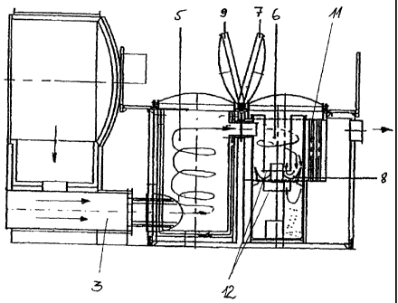
Figure 1 shows a gasification boiler in front view in section,
Figure 2 shows the side view of the entire heating installation in
section,
Figure 3 shows a plan view of the entire heating installation, and
Figure 4 show an enlargement around the ash separator of Figure 2.
Detailed Description

A fuel and gasification space 1 and, below it, a horizontal,
cylindrical combustion space 3 are arranged in a housing. A
filling door for the bales of straw and two doors for the removal
of ash are fixed on the front side. At the lower apex of the fuel


CA 02542676 2010-01-08
-

and gasification space 1, there is a longitudinal slot in the
bottom extending over the entire depth. A grating 2 is embedded
in said longitudinal slot. Situated below the grating 2 are gas
nozzles which lead into a combustion space 6. The latter
5 comprises pipe sections of refractory concrete which are guided in
a steel pipe. The fuel and gasification space 1 has depressions 4
parallel to the grating 2 and combustion space 3. Said
depressions are of half-shell-shaped design. The wall has a
respective door in the end region for the removal of ash.
The heating boiler with fuel and gasification space 1 and
combustion space 3 is designed as a constructional unit.

The combustion chamber 5, ash separator 6 and heat exchanger which
are arranged downstream are brought together by means of a
framework 10 to form a further constructional unit.

Combustion chamber 5 and ash separator 6 have a cylindrical
housing standing perpendicularly. The walls of the housings are
insulated and the latter are closed at the top by a shell-shaped
cover.

In the ash separator, a pipe is fitted centrally in the upper
region and below it a circular baffle plate (8) is fitted in such
a manner that an annular opening for the depositing of ash remains
from the outer wall.

The adjoining heat exchangers are arranged in a vertical flue gas
vent.
A circulating air fan causes the combustion gases to have a
rotational movement in the fuel and gasification space 1. The
loose, heavy particles of the combustion matter accumulate in the
outer, lateral depressions 4 where they completely combust.
Lightweight airborne particles are carried along by the combustion


CA 02542676 2010-01-08
- 6 -

gas flow and at the latest are completely combusted in the
combustion chamber 5. Repeated separation of the ash takes place
in the ash separator 6. When gas is admitted, the ash particles
are pressed against the inner wall and, when deflected by the
baffle plate 8, drop downward. The removal of ash takes place
through the upper covers 7, 9 and a door in the bottom region of
the ash separator 6. The gas flow cleaned in this manner is
conducted across the heat exchangers.


CA 02542676 2010-01-08
- 7 -

List of reference numbers

1. Fuel and gasification space
2. Grating
3. Combustion space
4. Lateral depression
5. Combustion chamber
6. Ash separator
7. Cover combustion chamber
8. Baffle plate
9. Cover ash separator
10. Framework
11. Heat exchanger
12. Flue pipe

Representative Drawing
A single figure which represents the drawing illustrating the invention.
Administrative Status

For a clearer understanding of the status of the application/patent presented on this page, the site Disclaimer , as well as the definitions for Patent , Administrative Status , Maintenance Fee  and Payment History  should be consulted.

Administrative Status

Title Date
Forecasted Issue Date 2010-12-07
(86) PCT Filing Date 2004-10-07
(87) PCT Publication Date 2005-05-06
(85) National Entry 2006-04-13
Examination Requested 2007-10-18
(45) Issued 2010-12-07
Deemed Expired 2022-10-07

Abandonment History

There is no abandonment history.

Payment History

Fee Type Anniversary Year Due Date Amount Paid Paid Date
Application Fee $400.00 2006-04-13
Maintenance Fee - Application - New Act 2 2006-10-10 $100.00 2006-10-10
Maintenance Fee - Application - New Act 3 2007-10-09 $100.00 2007-10-03
Request for Examination $800.00 2007-10-18
Maintenance Fee - Application - New Act 4 2008-10-07 $100.00 2008-09-26
Maintenance Fee - Application - New Act 5 2009-10-07 $200.00 2009-10-02
Maintenance Fee - Application - New Act 6 2010-10-07 $200.00 2010-09-17
Final Fee $300.00 2010-09-20
Maintenance Fee - Patent - New Act 7 2011-10-07 $200.00 2011-10-06
Maintenance Fee - Patent - New Act 8 2012-10-09 $200.00 2012-10-02
Maintenance Fee - Patent - New Act 9 2013-10-07 $200.00 2013-10-02
Maintenance Fee - Patent - New Act 10 2014-10-07 $250.00 2014-10-07
Maintenance Fee - Patent - New Act 11 2015-10-07 $250.00 2015-10-05
Maintenance Fee - Patent - New Act 12 2016-10-07 $450.00 2017-09-19
Maintenance Fee - Patent - New Act 13 2017-10-10 $450.00 2018-08-27
Maintenance Fee - Patent - New Act 14 2018-10-09 $450.00 2019-02-26
Maintenance Fee - Patent - New Act 15 2019-10-07 $650.00 2020-10-07
Maintenance Fee - Patent - New Act 16 2020-10-07 $459.00 2021-04-07
Late Fee for failure to pay new-style Patent Maintenance Fee 2021-04-07 $150.00 2021-04-07
Maintenance Fee - Patent - New Act 17 2021-10-07 $459.00 2021-11-02
Late Fee for failure to pay new-style Patent Maintenance Fee 2021-11-02 $150.00 2021-11-02
Owners on Record

Note: Records showing the ownership history in alphabetical order.

Current Owners on Record
HERLT, CHRISTIAN
Past Owners on Record
None
Past Owners that do not appear in the "Owners on Record" listing will appear in other documentation within the application.
Documents

To view selected files, please enter reCAPTCHA code :


To view images, click a link in the Document Description column. To download the documents, select one or more checkboxes in the first column and then click the "Download Selected in PDF format (Zip Archive)" or the "Download Selected as Single PDF" button.

List of published and non-published patent-specific documents on the CPD .

If you have any difficulty accessing content, you can call the Client Service Centre at 1-866-997-1936 or send them an e-mail at CIPO Client Service Centre.


Document
Description 
Date
(yyyy-mm-dd) 
Number of pages   Size of Image (KB) 
Maintenance Fee Payment 2020-10-07 1 33
Maintenance Fee Payment 2021-04-07 1 33
Abstract 2006-04-13 1 28
Claims 2006-04-13 2 58
Drawings 2006-04-13 2 37
Description 2006-04-13 6 167
Abstract 2010-03-24 1 28
Representative Drawing 2006-06-21 1 13
Cover Page 2006-06-27 1 56
Description 2010-01-08 7 224
Claims 2010-01-08 2 59
Drawings 2010-01-08 3 48
Cover Page 2010-11-19 2 65
Representative Drawing 2010-11-19 1 18
Assignment 2006-04-13 2 67
PCT 2006-04-13 4 170
Assignment 2006-04-13 1 32
Correspondence 2006-04-28 1 34
Maintenance Fee Payment 2017-09-19 1 25
Prosecution-Amendment 2007-10-18 1 30
Prosecution-Amendment 2007-11-23 1 38
Prosecution-Amendment 2009-07-08 2 58
Maintenance Fee Payment / Reinstatement 2018-08-27 1 26
Prosecution-Amendment 2010-01-08 13 355
Correspondence 2010-09-20 1 32
Maintenance Fee Payment 2019-02-26 1 27
Correspondence 2012-02-16 3 79
Assignment 2006-04-13 4 110