Note: Descriptions are shown in the official language in which they were submitted.
CA 02542698 2006-04-11
IMPROVED APPARATUS FOR APPLICATION OF LIQUIDS OR LIQUID-
SOLID DISPERSIONS TO SOIL HAVING A PIVOTABLE JOINT
CONNECTOR
Field of the Invention
This invention relates to farm equipment, and in particular to an improved
apparatus for applying liquids or liquid-solid dispersions, such as liquid
manure, to soil.
Background of the Invention and Description of the Prior Art
Liquid manure is a valuable source of nutrients for agricultural crops.
Other nutrient streams, typically liquid or liquid-solid dispersions, may
include
effluent from food processing plants, municipal bio-solids from sewage
treatment
plants, or commercially-available liquid fertilizers.
In the case of prior art implements and methods for applying such liquid-
solid dispersions to tracts of land, a dragline system is typically used to
provide
the liquid-solid slurry to the implement for subsequent delivery to the soil.
In this
regard, a slurry in the form of a liquid-solid dispersion is pumped from a
lagoon
or storage tank to the field by a piping system, where it is delivered to an
application implement via a flexible dragline. In the field the flexible
dragline is
coupled to the application implement, and the implement while coupled to the
flexible dragline is pulled across the field by a tractor , typically in a
serpentine
fashion, and the dragline supplies the liquid-solid dispersion to the
implement for
delivery to the soil.
The implement may spread the slurry in a broadcast manner on the
surface of the soil, or more preferably apply the slurry in along the
cultivation
path of the implement or rows of live crop. Alternatively the implement may
blend or bury the slurry in furrows or mix it with the soil during aeration or
tillage
of the soil.
-1-
CA 02542698 2006-04-11
The tractor, which tows the application implement, due to flexibility of the
dragline, can follow a serpentine path in the field to give uniform coverage
of the
land while being operatively connected to the flexible dragline.
Typically, with respect to prior art devices which are used in this manner
and which have capability of being operatively coupled to a flexible dragline,
a
swing pipe (invariably a ho(zontal conduit extending rearwardly of the towed
implement) is provided on the towed implement which assists when the tractor
reverses direction at the end of a field being fertilized. One end of such
swing
pipe pivotally is connected to the implement ; the other connects to the
dragline,
which is in turn operatively connected to the liquid-solid dispersion
distribution
system. The swing pipe, by being pivotable, better transmits the forces
required
to pull the dragline in a tensile manner to the dragline. The function of the
swing
pipe is further to conduct the slurry to the implement for delivery to the
soil, and
further to provide clearance with the structure of the implement when the
tractor
makes turns in the field during its following of a serpentine path in the
field.
A number of soil tillage or soil aeration devices of the above type towed
by a tractor are currently commercially available. Such devices, in addition
to
applying liquid-solid dispersions to the soil, may further till or aerated the
soil at
the same time as a liquid or liquid-solid dispersion, such as liquid
fertilizer or
liquid manure, is applied to the soil.
One such prior art apparatus is a soil tillage and liquid manure applicator
8 of the type shown in Fig. 1 hereto. Such apparatus 8 comprises a frame 13
and is adapted to be towed behind a tractor (not shown) by attachment of the 3-
point hitch of the tractor to lug members 12 on apparatus 8. Gangs of tined
rollers 14 are provided, each provided with protruding tines 16 to penetrate
the
soil when apparatus 8 is towed over the soil. Flexible supply hose 20 is
-2-
CA 02542698 2006-04-11
adapted to be attached, at the rear of apparatus 8, to swing pipe 50 which is
in
turn coupled in fluid communication with a vertically-extending manifold 26
which
is rotatable about vertical axis 30 to allow pivotable movement of swing pipe
50
in the direction shown by arrows "A". A plurality of flexible supply tubes 36
extend from flanges 32 on vertical manifold 26 to various points along the
frame
13 of apparatus 8 to allow the liquid manure to be directed to the soil at
various
points along the front of apparatus 8 in front of the gangs of tined rollers
14.
Disadvantageously, however, with apparatus 8 of the prior art, pivoting
of vertical manifold 26 during pivotable movement of swing pipe 8 causes wear
and friction in the many flexible supply tubes 36, resulting in necessary and
frequent replacement thereof. As typically many individual supply tubes 36 are
incorporated in such prior art apparatus 8 shown in Fig. 1(only four are shown
but frequently many more are employed) this is a serious and important
drawback to the implementation and continued use of such prior art apparatus
8.
Another prior art soil aerating and manure applicator apparatus is the
prior art apparatus 9 shown in Fig. 2 hereto.
As shown in Fig. 2, prior art apparatus 9 comprises a frame 13 which
may be towed by a tractor (not shown) over the ground. A swing pipe 50, having
fixed collar 56 thereon, is provided, for attachment to a flexible supply hose
(not
shown) . Swing pipe 50 is corralled and rotatably positioned within frame
members 15 of apparatus frame 13, and is thus pivotably rotatable in the
direction of arrows "A" about vertical axis 30.
Swing pipe 50 is coupled to and in fluid communication with a flexible
conduit member 54 at one end of conduit member 54. The opposite end of
flexible conduit member 54 is in fluid communication with manifold 26, which
serves to distribute the supply of liquid manure to various points along frame
13
-3-
CA 02542698 2006-04-11
via numerous supply tubes 36 extending therefrom. Such supply tubes 36
further extend in proximity to tines 16 on gangs of tined rollers 14, to allow
liquid manure to be mixed in with soil during the passage of the gangs of
tined
rollers 14 over the soil.
Disadvantageously with the prior art apparatus 9 of Fig. 2, during
pivoting of swing pipe 50 it is necessary that flexible conduit 54 twist to
permit
such pivotable movement of swing pipe 50. This has the undesirable effect that
conduit 54 may sometimes kink, depending on the degree of twist and the
pressure to which such flexible conduit is subject. In addition, twisting of
conduit
54 results in wear to flexible conduit 54 necessitating its replacement from
time
to time.
Accordingly, a real need exists for an improved apparatus capable of
applying liquid-solid dispersions to soil, having a horizontal supply conduit
which
pivots in at least the horizontal plane, and preferably also in the vertical
plane,
yet be durable and require little or more simplified maintenance.
Summary of the Invention
The present invention thus relates to an improved apparatus adapted for
providing liquids or liquid solid dispersions, typically a liquid manure
dispersion that is supplied to the apparatus via a flexible supply hose, to
soil.
One of the major improvements in the apparatus of the present
invention relates to providing means of permitting coupling of a conduit on
the
apparatus to the flexible supply hose which allows pivotable movement of the
point of connection to such flexible supply hose, thereby allowing more direct
transmittal of tensile pulling forces to the flexible supply hose and thus
-4-
CA 02542698 2006-04-11
reducing the incidence of non-axial applied forces to such supply hose which
may otherwise cause or contribute to kinking of such supply hose, while at
the same time ensuring a reliable and durable fluid connection of the flexible
supply hose to the apparatus and ultimate trouble-free supply of the liquid
dispersion to the soil.
Accordingly, in a broad aspect thereof, the present invention provides
for an apparatus for application of liquid and liquid solid solutions to soil,
comprising a boom member which is pivotably coupled to a frame, and which
supports and which is secured to a portion of a fluid conduit. A further
portion of the fluid conduit is flexible and bendable to allow the boom member
to which the fluid conduit is fixedly attached for a portion of its length to
pivot
about its point of pivotable coupling to the frame. A distal end of the
conduit
is adapted to be attached to a flexible supply hose, which does not form a
part of the invention, which supply hose supplies liquid and liquid-solid
dispersions to the apparatus.
As a result of possessing a flexible coupling and a further flexible
conduit portion, the apparatus, when connected to the flexible supply hose,
may more directly transmit axial pulling force to the flexible supply hose via
the boom member, due to the boom member being able to pivot and more
direct transfer of axial pulling forces to the flexible supply hose and
thereby
reduce the tendency of the flexible supply hose to kink and thereby restrict
or
block the supply of liquid or liquid solid dispersions to the apparatus.
Thus, in a broad aspect of the present invention, the improved
apparatus of the present invention for applying a liquid or a liquid-solid
dispersion to soil comprises :
frame means;
-5-
CA 02542698 2006-04-11
a manifold ;
a plurality of flexible tube members, at one end thereof in
fluid communication with said manifold and an other end thereof
adapted to permit delivery of said liquid or said liquid-solid dispersion
to said soil;
a boom member, having a distal end and a proximal end;
conduit means, at a proximal end thereof in fluid
communication with said manifold and at a distal end thereof fixedly
coupled to said distal end of said boom member, an intermediate
portion of said conduit means being flexible, said conduit means at
said distal end further being rigid and adapted to be releasibly
coupled to a flexible supply hose; and
means for pivotably coupling said boom member at its
proximal end to said frame means so as to allow pivotal movement
of said distal end of said boom member in at least a horizontal
plane;
wherein said distal end of said conduit means is thus
permitted to pivot in a horizontal plane by said boom member and by
said intermediate flexible portion of said conduit means.
Advantageously, using such configuration there is no necessity that the
manifold for distribution of the liquid slurry to the soil be pivotable, nor
that the
accompanying individual distribution hoses which supply the liquid dispersion
to
the soil be required to be flexible in either the vertical or horizontal
planes.
-6-
CA 02542698 2006-04-11
Likewise, the problems of the prior art apparatus which required
twisting (torsion) of a flexible conduit in order to permit movement of the
flexible
supply hose when coupled to the apparatus , and the resultant frequent kinking
of such flexible conduit due to such torsion, is thereby advantageously
avoided
with the design of the present invention.
In a preferred embodiment of the apparatus of the present invention the
means for pivotably coupling the boom member at its proximal end to the frame
means further comprises means to permit pivotable movement of said boom
member in a vertical plane. Such means to permit pivotable movement of the
boom in the vertical plane may comprise a universal joint to permit pivotable
movement in both a vertical plane and in a horizontal plane, or similar joint
means permitting a range of pivotal motion of the boom member in both a
vertical
plane and in a horizontal plane. Such means may alternatively comprise a pair
of pivotable joint connections of the boom member to the frame, a first
pivotable
connection permitting pivotable movement in a vertical plane, and a second
pivotable connection permitting pivotable movement in a horizontal plane.
In a further refinement of the apparatus of the present invention, means
is further incorporated into the pivotable connection of the boom member to
the
frame which serves to limit the degree of pivotal movement in the horizontal
and/or vertical plane. In a preferred embodiment such means for limiting the
degree of pivotable movement comprises a pin member.
In yet a further refinement of the apparatus of the present invention, a
hydraulic cylinder may be mounted at one end thereof to the frame means at
another end thereof to said boom member, adapted upon actuation to cause
pivotable rotation of said boom member in said vertical plane about said means
-7-
CA 02542698 2006-04-11
to permit pivotable movement so as to thereby cause said boom member to pivot
in said vertical plane and thereby raise said distal end of said boom member.
Brief Description of the Drawings
Further advantages and permutations will appear from the following
detailed description of various non-limiting embodiments of the invention,
taken
together with the accompanying drawings, in which:
FIG. I is a perspective view of a prior art aeration and liquid manure
application device which may be towed by and attached to a three-point hitch
of
a tractor, which utilizes a vertically extending pivotable manifold to which a
horizontally extending conduit is attached ;
FIG. 2 is a perspective view of another prior art aeration and liquid
manure application device which similarly may be towed by a tractor, which
utilizes an "L" shaped conduit having a collar, to which a chopper manifold is
in
fluid communication via a flexible hose;
FIG. 3 is an embodiment of an improved apparatus of the present
invention for application of liquid-solid dispersions to soil, having a
substantially
horizontally extending boom member pivotably coupled to the frame of the
apparatus;
Fig. 4 is a cross-sectional view along plane 4-4 of Figure 3;
FIG. 5 is a view similar to Fig. 4 showing an alternative arrangement of
the pivotable connection;
-8-
CA 02542698 2006-04-11
Fig. 6 is a perspective view of a further embodiment of the improved
apparatus of the present invention, incorporating a slightly modified
pivotable
joint connection;
Fig. 7 is a side view in the direction of arrow "B" of Fig. 6;
Fig. 8 is a view similar to Fig. 7, showing a further embodiment of the
pivotable connection of the present invention;
Fig. 9 is a view similar to Fig. 7, showing yet a further embodiment of ~
the pivotable connection of the present invention;
Fig. 10 is a detailed view of the pivotable connection shown in Fig. 5,
when said distal end (ie right hand side) of said boom member is angled
vertically downward; and
Fig. 11 is a view of the pivotable connection shown in Fig. 10, when the
connection is pivoted approximately 75 and the distal end (ie right hand
side) of
said boom member is angled vertically upward.
Detailed Description of Some Preferred Embodiments
In all figures, for consistency, identical components are identified with
identical reference numerals.
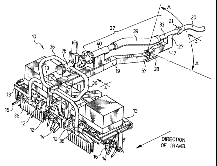
Fig. 3 shows apparatus 10 of the present invention, in one embodiment
thereof, for spreading liquid or solid-liquid dispersions to soil, adapted to
be
towed behind a tractor (not shown) by means of towing or by means of
attachment to a 3-point hitch of a tractor via attachment lugs 12.
-9-
CA 02542698 2006-04-11
Apparatus 10 of the present invention comprises a frame 13, adapted to
support gangs 14 of tines 16 , such tines individually penetrating the soil
when
apparatus 10 is towed over the soil, for aeration of the soil during
application of
liquid or liquid-solid dispersions, fertilizers, or slurries to the soil.
Such liquids or liquid-solid dispersions are supplied under pressure to
apparatus 10 via a flexible supply hose 20, which is removably fluidly coupled
to
apparatus 10 via a flange 21 or other commonly-employed fluid coupling, as
shown in Fig. 3.
Supported on frame 13 of apparatus 10 is manifold 76, to which are
attached a plurality of individual supply tubes 36 which supply liquid solid
dispersions from manifold 76 to the soil proximate individual tines 16 on
gangs of
rollers 14, to thereby ensure the liquid solid dispersions are able to
penetrate
and be absorbed by the soil.
As seen in Fig. 3, a first end of each supply tube 36 is in fluid
communication with manifold 76, and an opposite end situated close to the
surface of the soil to permit delivery of liquid or liquid-solid dispersions
to the
soil.
For reasons more fully elaborated on below, an elongate boom member
17, having a distal end 27 and a proximal end 28, is provided. Boom member 17
is pivotably coupled, at its distal end 28, to an elongate member 19 [which
forms
part of frame 13 of apparatus 10] by pivotable coupling 57 . The manner of
pivotable coupling and operation of pivotable coupling 57 is further
described,
below.
Conduit means 37 is further provided, for conveying liquid or solid-liquid
dispersions from flexible supply hose 20 to manifold 76. Conduit means 37 is
-10-
CA 02542698 2006-04-11
comprised of an intermediate flexible portion 39, a rigid distal end 33
adapted
for releasable coupling to flexible supply hose 20 via flange 21, and a rigid
proximal end 40. Proximal end 40 of conduit 37 is adapted for fluid
communication with manifold 76, as shown in Fig. 3.
Rigid distal end 33 of conduit means 37 is further rigidly secured to, and
adapted to be supported by, distal end 27 of boom member 17.
As best seen from Fig. 4 and Fig's. 10 and 11, pivotable coupling 57
couples distal end 28 of boom member 17 to elongate frame member 19, and
comprises a vertical pin member 60 which passes through apertures 61 in each
of protruding tabs 28a of boom member 17, and protruding tabs 19a of elongate
frame member 19, so as to pivotably secure elongate frame member 19 to boom
member 17. Distal end 27 of boom member 17, with distal end 33 of conduit
means 37 rigidly secured thereto, is accordingly permitted to pivot in a
horizontal
plane .
In the embodiment of the pivotable coupling 57 shown in Fig.s 10 & 11,
oversized apertures 61 permits some pivotable movement of boom member 17 in
the vertical plane (the plane of the paper in Fig. 10). However, as may be
seen
from Fig.'s 10 and 11, the diameter of pin member 61 relative to the (greater)
diameter of apertures 61 in tabs 19a and 28a serves to limit the amount (ie
degree) of angular pivoting of the distal end 27 of boom member 17 in the
vertical plane.
Advantageously, with such structural configuration, no tensile loads are
applied to flexible intermediate portion 39 of conduit means 37 during pulling
of
flexible supply hose 20 . Rather, all such tensile loads on said flexible
supply
hose 20 are provided via elongate frame member 19, pivotable coupling 57, and
boom member 17.
-11-
CA 02542698 2006-04-11
Also advantageously, although flexible intermediate member 39 due to it
being able to bend permits pivotable movement of the distal end 33 of conduit
means 37 in a horizontal plane, no twisting or torsion results to intermediate
member 39, and thus kinking , blockage, or unacceptable wear of intermediate
flexible portion 39 is avoided.
In another variation of the pivotable coupling 57 employed in the present
invention, as may be seen from Fig. 5, a universal joint 72 may be employed
for
pivotable coupling 57. As may also be seen from Fig. 5, in order to limit the
degree of pivotal motion of boom member 17 in the vertical plane to a fixed
angular rotation "a" and thereby avoid flexible supply tube 20 dragging on the
ground, in a preferred embodiment a pin member 60 may be incorporated into
universal joint 72 and adapted to extend into an oversize aperture 71 in
protruding tab 19a of elongate arm 19, so as to act as a guide and limit the
maximum upward and downward pivotal movement of distal end 27 of boom
member 17 in the vertical plane. In a preferred embodiment "a" is
approximately
5-90 and preferably about 100.
Fig. 6 shows another apparatus 11 of the present invention, with
features identical to Fig. 3 being identified with identical numerals. A
vertical
manifold 26 is provided in this embodiment, having a plurality of flanged
hydrants
34a-d, to which flexible supply tubes 36 are fluidly coupled.
As seen in Fig. 6 and in greater detal in Fig. 7, a universal joint 72 is
provided for pivotable coupling 57 to allow pivotable coupling of boom member
17 to elongate arm member 19 of frame 13. Notably, unlike the universal joint
72
shown in Fig. 5 having a pin member 60 to limit the angular rotation a of boom
member 17 , in the embodiment shown in Fig. 6 such means for limiting the
amount of angular movement comprises mating surfaces 97 and 98 on
-12-
CA 02542698 2006-04-11
lowermost extremities of elongate arm member 19 and boom member 17,
respectively, to limit the amount of vertical downward angular rotation a of
boom
member 17 below the horizontal.
Fig. 8 shows a further modification to the configuration shown in Fig. 7,
wherein a hydraulic cylinder 100 is provided, adapted to be supplied with
pressurized hydraulic fluid from the towing tractor (not shown) via hydraulic
supply line 102.
The purpose of such hydraulic cylinder 100 is two-fold.
Firstly, such hydraulic cylinder 100 serves to raise and lower as desired
distal end 33 of conduit means 37 to facilitate connection and de-coupling of
supply hose 20. In such manner the operator of the apparatus 11, if a kink is
seen to develop or have occurred in the flexible supply hose 20 during for
example turning of the apparatus 11 in the field, to raise or lower the distal
end of
conduit 33 to better or more directly apply tensile loads to supply hose 20
and
thereby reduce or avoid the incidence of kinking. Advantageously, such
configuration permits the operator of the apparatus 11 and the towing tractor
(not
shown) to make such adjustments from the cab of the tractor by operation of
the
tractor hydraulics in the cab of the tractor without having to stop the
tractor,
disembark from the cab, and physically man-handly the distal end 33 of conduit
means 37 to attempt to more directly align the distal end 33 of conduit means
37
with flexible supply hose 20 to thereby avoid kinking of the latter.
Secondly, hydraulic cylinder 100 serves to limit the amount of angular
pivoting (ie vertical movement) of distal end 33 of conduit means 37 below the
horizontal, thereby preventing distal end 33 (and attached flexible supply
hose
20) from becoming substantially vertical and thereby subjugating supply hose
20
-13-
CA 02542698 2006-04-11
( which typically lying on the field and thus horizontal) to a substantially
right-
angle bend and thus a potential kink in supply hose 20.
In the embodiment shown in Fig. 8, hydraulic cyiinder 100 is mounted at
one end to distal end 19a of elongate arm member 19 (part of frame 13), and at
another end mounted to boom member 27. Upon actuation such hydraulic
cylinder is adapted to cause pivotable upward rotation of boom member 17 in a
vertical plane about pivotable coupling 57 and thereby raise distal end 33 and
flexible supply hose 20 when coupled thereto.
Fig. 9 shows a further alternative embodiment of the pivotable coupling
57 of boom member 17 to elongate arm member 19 of frame 13, wherein instead
of a single pivotable connection in the form of a single universal joint 72
comprising pivotable coupling 57 as shown in Fig's. 7 & 8, such pivotable
coupling 57 comprises a first pivotable connection 80 to permit pivotable
movement of boom member 17 in a horizontal plane, and a second pivotable
connection 81 to permit pivotable movement of boom member 17 in a vertical
plane.
In a preferred embodiment as shown in Fig. 9, a hydraulic cylinder 100
may further be provided , for the purpose inter alia of limiting the extent of
downward angular rotation of boom member 17 as described above.
Alternatively, pivotable connection 81 may further comprise means for limiting
the extent of downward angular movement of boom member 17 by having a
lowermost extremity of elongate arm member 19, such as a mating face 97 as
utilized in the embodiment of the invention shown in Fig. 7, serve to limit
the
extent of permitted downward vertical movement of distal end 33 of conduit
means 37.
Although the disclosure described and illustrates preferred embodiments
of the invention, it is to be understood that the invention is not limited to
these
-14-
CA 02542698 2006-04-11
particular embodiments. Many variations and modifications will now occur to
those skilled in the art. For definition of the invention, reference is to be
made to
the appended claims.
-15-