Note: Descriptions are shown in the official language in which they were submitted.
CA 02542872 2006-04-18
WO 2005/044615 PCT/US2004/034011
TITLE
SUPPORT POST WITH LOCKING FEATURE
BACKGROUND
Field of the Invention
This patent relates to protective packaging for large
products such as household appliances. More particularly,
this patent relates to a packaging system that includes
laminated paper support posts that interlock with an EPS
base or top cap.
Description of the Related Art
The usual practice in the appliance manufacturing
industry has been to fasten the bottom of the appliance to a
wooden pallet or other type of base during manufacture. The
base is dimensioned to be oversized relative to the
appliance's width and depth so that the perimeter of the
base extends beyond the appliance perimeter. After the
appliance has been completely assembled (and while it is
mounted on the base) a rigid but collapsible four-sided
corrugated box or sleeve having open top and bottom ends is
placed over the appliance and secured to the base. Before a
top cap is placed over the box, support posts (a.k.a. corner
posts) are inserted at each corner of the appliance between
the appliance and the corrugated sleeve so that the posts
extend from the base up to the top cap. The corner posts
fit snugly against the vertical corners of the packaged
appliance to cushion and protect it. The result is a
packaged appliance that is protected from impacts, but
cannot be viewed without removing the corrugated box.
( CA 02542872 2009-02-02
WO 2005/044615 PCT/US2004/034011
2
A trend in the appliance industry has been to package
appliances in open-sided (see-through) packages. Open-sided
packages do not incorporate a four-sided corrugated box or
sleeve. Instead, the open-sided package is wrapped in clear
plastic film.
A typical open-sided package for appliances consists of
a molded expanded polystyrene (EPS) base and top cap and
molded EPS corner protectors that interlock into the base
and top cap. An advantage of EPS packages is their
interlocking capability. A disadvantage of EPS packages is
that stacking strength is achieved by stacking through the
appliance since the EPS corner protectors provide minimal,
if any, stacking strength.
Sonoco Products CompanyTM, the assignee of the present
invention, has developed a primarily paper-based open-sided
package having high-strength load bearing corner posts. The
primarily paper-based package comprises a base on which the
appliance is secured, a top cap, and wound paper corner
posts. Because the corner posts do not interlock with the
base, the base is placed within a paper bottom tray which
helps hold the corner posts against the corners of the
appliance. Unlike the molded EPS package, stacking strength
is provided by the corner posts, not by the appliance.
Additional posts may be used as horizontal braces to provide
added strength protection for clamp lifting.
The paper-based open-sided package can withstand
substantial stacking, clamping and lifting forces. However,
in some applications, such as in the packaging of
dishwashers, the bottom tray may be exposed to wet
CA 02542872 2006-04-18
WO 2005/044615 PCT/US2004/034011
3
conditions, making it desirable to use a water-resistant
tray.
Thus it is an object of the present invention to
provide an open-sided package for a large appliance that
eliminates the paper bottom tray by providing a paper corner
post that interlocks with a molded EPS base and/or top cap.
A further object of the present invention is to provide
an open-sided package in which the corner posts, not the
appliance, bear the stacking load.
Another object of the present invention is to provide
an open-sided package for a large appliance that can
withstand substantial stacking, clamping and lifting forces.
Further and additional objects will appear from the
description, accompanying drawings, and appended claims.
CA 02542872 2006-04-18
WO 2005/044615 PCT/US2004/034011
4
SUMMARY OF THE INVENTION
The present invention is an improved open-sided
packaging assembly for protecting and cushioning a product
such as a large appliance. The assembly comprises a water-
resistant molded EPS base, a top cap, and four paper corner
posts extending from the base to the top cap. The corner
posts are shaped in such a way that when they are inserted
into the base or top cap they do not fall out. More
specifically, the corner posts have locking portions at
their bottom and top ends that enable them to interlock with
the molded EPS base and top cap.
In one particular embodiment the invention comprises
four longitudinal support posts, each having a bottom end
and two integrally formed locking tabs disposed at the
bottom end, and a rectangular base having openings disposed
therein at each corner, the openings being configured to
receive the bottom ends of the support posts in interlocking
fashion. The support posts are formed from a sheet of
paper wound into a tubular structure comprising an outer
wall and an inner, product-facing wall substantially
coextensive with the outer wall and joined to the outer wall
at outer ends to define a hollow space therebetween. The
two locking tabs are located at the outer ends of the post.
Each of the locking tabs is substantially planar and is
formed from adjacent portions of the outer wall and the
inner wall.
In a key feature of the invention, the two locking tabs
are oriented on non-parallel planes so as to prevent the
post from moving in any lateral direction during use. The
CA 02542872 2006-04-18
WO 2005/044615 PCT/US2004/034011
locking tabs are spaced inwardly from the outer perimeter of
the base so that portions of the base abut each outer wall
member to help hold the posts in place.
In a second embodiment, each of the paper corner posts
5 has a polygonal locking portion disposed at the bottom end
for interlocking with the molded EPS base. The polygonal
locking portion preferably is a hollow tubular subsection of
the post. For added stability, the corner posts may also
have a substantially planar locking tab located at one outer
end.
CA 02542872 2006-04-18
WO 2005/044615 PCT/US2004/034011
6
THE DRAWINGS
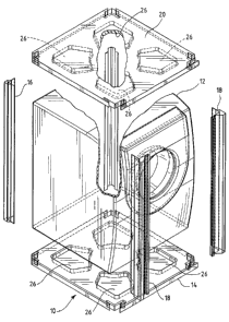
Figure 1 is a perspective view of an open-sided
packaging assembly according to the present invention,
including the molded EPS shipping base and the rear and
front corner posts.
Figure 2 is an exploded view of the packaging assembly
of Figure 1.
Figure 3 is a top plan view of the shipping base of
Figure 1.
Figure 4 is a top plan view of one of the rear corner
posts of Figure 1.
Figure 5 is a top plan view of one of the front corner
posts of Figure 1.
Figure 6 is a top plan view of the corner posts and
shipping base of Figure 1.
CA 02542872 2006-04-18
WO 2005/044615 PCT/US2004/034011
7
DETAILED DESCRIPTION OF THE INVENTION
Turning to the drawings, there is shown in Figures 1
and 2 a preferred embodiment of the present invention, a
packaging assembly 10 for protecting and cushioning a
product such as a large appliance 12. The packaging
assembly 10 comprises a base 14, two rear corner posts 16
and two front corner posts 18 affixed to the base 14, and a
top cap 20. Optional transparent film (not shown) may be
wrapped around the package 10 or draped over the product 12
to protect the product 12 from dust and dirt.
As best shown in Figure 3, the base 14 is substantially
rectangular and symmetrical about a front to rear central
axis. The base 14 has portions for supporting the product
and may have additional openings (not shown) for
accommodating product feet. Openings 22, 24 at the rear and
front corners have the same shape at the cross-sectional
shape of the bottom ends of the rear and front corner posts
16, 18 in order to receive the corner posts 16, 18 in
interlocking fashion. Preferably the base 14 is formed of
water-resistant molded expanded polystyrene (EPS) and may
have large depressions 26 disposed in the base 14 to lessen
the amount of material required to make the base 14. The
base 4 has an outer perimeter 15 somewhat larger than the
perimeter of the product so that corner posts that interlock
with the base 14 at the corners of the base 14 fit around
the product 12 exterior.
Figures 4 and 5 are top plan views of the rear and
front corner posts of Figure 1, respectively. Directing the
CA 02542872 2006-04-18
WO 2005/044615 PCT/US2004/034011
8
reader's attention to Figure 4, the rear corner posts 16
comprise an outer wall 28 made up of members 36, 38 and a
substantially L-shaped inner, product-facing inner wall 30
substantially coextensive with the outer wall 28 and joined
to the outer wall 28 at ends 32, 34 to define a hollow space
therebetween. The two mirror-image outer wall members 36,
38 are joined at a right angle along an outer edge 40 and
extend from the outer edge 40 to the outer ends 32, 34.
Beginning at the outer edge 40, the outer wall members 36,
38 comprise first, proximate sections 42, 44 extending at
right angles from the outer edge 40, second, intermediate
sections 46, 48 extending angularly inward (in the direction
of the product) from the first sections 42, 44 toward
engagement with the inner wall 30, and third, distal
sections 52, 54 extending from the second sections 46, 48 to
the ends 32, 34. The first sections 42, 44 define the outer
perimeter of the corner post 16 (and package assembly 10)
and thus make contact with the transparent film wrapping if
it is used. The third sections 52, 54 are substantially
parallel to the first sections 42, 44 in the preferred
embodiment and are in close proximity or adjacent to the
inner wall 30.
Still referring to Figure 4, the rear corner post inner
wall 30 comprises two planar inner wall members 56, 58
joined at a right angle along an inner corner 50 adjacent
the product. Each inner wall member 56, 58 extends from the
inner corner 50 to one of the outer ends 32, 34.
The distal sections of the inner wall members 56, 58
adjacent the distal sections 52, 54 of the outer wall 28
CA 02542872 2006-04-18
WO 2005/044615 PCT/US2004/034011
9
form locking tabs 60. As explained further below, the
locking tabs 60 fit within the rear openings 22 in the base
14. In a key aspect of the invention, the locking tabs 60
are substantially planar but are oriented on non-parallel
planes, so together they prevent the corner post from moving
in any lateral (horizontal) direction, thereby locking the
rear corner posts 16 in place.
In another key aspect of the invention, the locking
tabs 60 are spaced inwardly from the corner post outer
perimeter a distance S (delta). Consequently, as best shown
in Figure 6, tongue portions 99 of the base 14 abut the
outer wall 28 of the rear corner posts 16 to help hold the
corner post 16 in place. Specifically, the base 14 abuts
the second portions 46, 48 and third portions 52, 54 of the
rear post outer wall members 28. The distance S should be
large enough so that the portion 99 of the base interposed
between the corner post 16 and the perimeter 15 of the base
14 is wide enough to prevent breaking during use.
Figure 5 is a top plan view of a second embodiment of a
corner post according to the present invention, one that in
the illustrations is used for the front corner posts 18.
Each front corner post 18 has a hollow, tubular locking
portion 90 as described more fully below and, for added
stability, a substantially flat locking tab 80 similar in
shape and function to the rear corner post locking tabs 60.
Like the rear corner posts 16, each front corner post
18 comprises an outer wall 62 made up of members 72, 74 and
a substantially L-shaped inner, product-facing wall 64
substantially coextensive with the outer wall 62 and joined
CA 02542872 2006-04-18
WO 2005/044615 PCT/US2004/034011
to the outer wall 62 at ends 66, 68 to define at least one
hollow space therebetween. The outer wall first and second
members 72, 74 are joined at a right angle along an outer
edge 70 and extend from the outer edge 70 to the outer ends
5 66, 68.
The outer wall first member 72 is similar in shape to
the rear corner post outer wall members 36, 38. Beginning
at the outer edge 70, the outer wall first member 72
comprises a first, proximate section 76 extending from the
10 outer edge 70, a second, intermediate section 78 extending
angularly inward from the first section 76 toward engagement
with the inner wall 64, and a third, distal section 82
extending from the second section 78 to the first end 66.
The third section 82 is substantially parallel to the first
section 76 and together they define a locking tab 80 similar
in shape and function to the rear corner post locking tabs
60.
The outer wall second member 74 extends in a non-planar
fashion from the outer edge 70 to an end 68 where it meets
the inner wall 64. A first planar section 83 extends from
the outer edge 70 at a right angle to the outer wall first
member first section 76 to define the outer perimeter of the
front corner post 18. The outer wall second member 74 is
provided with an inwardly directed bead 84 having an apex 86
in close proximity with or adjacent the inner wall 64. The
bead 84 divides the corner post 18 into two longitudinal,
tubular, hollow subsections 88, 90. The smaller hollow
subsection 90 may be either fully or partially enclosed and
functions as a locking portion to further lock the corner
CA 02542872 2006-04-18
WO 2005/044615 PCT/US2004/034011
11
post 18 into the base 14. As explained further below, the
front corner post locking tab 80 and locking portion 90 fit
within the front openings 24 in the base 14 to hold the
front corner posts 18 in place.
The front corner post locking tab 80 is spaced inwardly
from the corner post outer perimeter so that, as best shown
in Figure 6, tongue portions 99 of the base 14 abut the
outer wall 62 of the front corner posts 18. Specifically,
the base 14 abuts the second portion 78 and third portion 82
of the front corner post outer wall member 72. The locking
tab 80 should be spaced far enough inward from the outer
perimeter so that the portion 99 of the base 14 interposed
between the corner post 18 and the perimeter 15 of the base
14 is wide enough to prevent breaking during use.
Likewise, the hollow subsection 90 that functions as a
locking portion should be spaced far enough inward from the
corner post outer perimeter so that the portion 92 of the
base 14 interposed between the corner post 18 and the base
perimeter 15 is wide enough to prevent breaking during use.
Since the locking portion 90 is polygonal, i.e., it
abuts the base 14 on at least three sides (as opposed to two
sides for the locking tabs 80), it can by itself prevent the
corner post 18 from moving laterally and thus the additional
locking tab 80 is not necessary. However, the locking tab
80 increases the stability of the package assembly by
providing additional interlocking capability. The locking
portions 90 may also be more suitable than the locking tabs
80 on the sides where the appliance has protrusions.
CA 02542872 2006-04-18
WO 2005/044615 PCT/US2004/034011
12
Figure 6 is a top plan view showing the rear and front
corner posts 16, 18 interlocked with the shipping base 14.
A dashed line indicates the outer dimensions of the product
12, which is not shown. The corner post locking tabs 60, 80
and the front corner post locking portions 90 fit within the
openings 22, 24 (Figure 3) in the base 14 to lock the corner
posts 16, 18 in position without the aid of a bottom tray as
in previous open-sided paper-based packaging designs. The
locking features (i.e. the locking tabs 60, 80 and the
hollow locking portion 90) are spaced inwardly (offset) from
the outer perimeter of the corner posts 14, 16 in order that
a portion of the base 14 may fit around the outside of the
locking features away from the product 12.
The packaging system 10 may also include a top cap 20
that covers the top of the product 20. For simplicity, the
top cap 20 may have the same configuration as the base 12 so
that the upper ends of the corner posts 16, 18 can be
inserted into openings in the top cap 20, as shown in Figure
1.
Preferably, both the base 12 and the top cap 20 are
formed of molded expanded polystyrene (EPS) material.
Alternatively, the base 12 and/or top cap 20 may be formed
of any suitable material that can be shaped, formed or die
25- cut to make openings for receiving the corner posts.
The corner posts are preferably formed from a sheet of
wound laminated paper, such as those manufactured by Sonoco
Products Company of Hartsville, South Carolina and described
in numerous United States and foreign patents, including
CA 02542872 2009-02-02
WO 2005/044615 PCTIUS2004/034011
13
Hughes U.S. Patent No. 5,267,651, Ortlieb U.S. Patent No.
5,593,039, Qiu U.S. Patent No. 6,186,329,=Muyskens U.S.
Patent No. 6,247,596 and Stebelton U.S. Patent No.
6,513,662. These corner posts basically are shaped paper
tubes and are made from a single sheet of paper wound
into a tube and shaped into the desired shape, typically
one with a modified "L" shaped cross section to fit smugly
about the vertical edge of the appliance. The corner posts
possess significant load bearing capability.
Although in the illustrated preferred embodiment the
rear corner posts 14 and front corner post 16 have different
designs, it should be understood that they need not
different. For example, the packaging assembly could be
comprised solely of posts having locking tabs similar to the
rear corner post 16 illustrated in Figure 4 or solely of
posts having a locking tab and a polygonal locking portion
similar to the front post 18 illustrated in Figure 5.
Alternatively, the corner posts could comprise a single
polygonal locking portion and no locking tab.
The locking features may be of any suitable
configuration that interlocks with the base and/or top cap.
For example, each corner post could have a single
substantially L-shaped locking tab that could by itself
adequately prevent lateral movement of the corner post.
Further modifications and alternative embodiments of
the invention are contemplated which do not depart from the
scope of the invention as defined by the foregoing teachings
and appended claims. It is intended that the claims cover
CA 02542872 2006-04-18
WO 2005/044615 PCT/US2004/034011
14
all such modifications that fall within their scope.