Note: Descriptions are shown in the official language in which they were submitted.
CA 02543178 2006-04-21
WO 2005/045283 PCT/US2004/035184
BOLTED PILOT WEB WITH PRECISION MACHINED BEARING STOP
FIELD OF THE INVENTION
The present invention relates to a bolted pilot web with a precision machined
bearing stop.
BACKGROUND OF THE INVENTION
A known bolted pilot web is found in US Patent No. 4,004,472. This patent
describes a detachable bearing support secured to a housing by a series of
bolts. The
bearing support is made from cast iron to ensure that the inner bearing
assembly does
not work loose during operation of the differential unit. The bearing support
is
detachable in order to provide a method for mounting the drive pinion in the
housing.
US Patent No. 6,544,140 provides a pinion mounting comprising a race attached
to the casing of the differential gear mechanism by a plurality of bolts. The
bolts are
installed through a plurality of mounting holes in the radial flange of the
race. The race
is in constant contact with the casing, resulting in no gap therebetween.
The above-described designs have several disadvantages. Known heavy and
single tandem axle designs include the integration of the pinion bearing cage
into the
carrier casting. Because of the relative shape and position of the pilot web
relative to
the remainder of the carrier assembly, casting the carrier as a single piece
is more
complex and not a cost effective casting process. Attempts at bolting the
pilot web to
the remainder of the carrier assembly have resulted in unacceptable
transference of
forces, and the bolts coming loose under load.
SUMMARY OF THE INVENTION
The present invention defines a pilot web and differential carrier assembly. A
pilot web, with a first end and a second end, contains at least one aperture
located at
each of said first and second ends. A differential carrier comprises at least
two
apertures in complementary locations to said apertures of said pilot web. A
first stop
on the pilot web aligns with a second stop on the differential carrier. The
second stop is
disposed adjacent to, and aligned with, the first stop, with the first and
second stops
CA 02543178 2006-04-21
WO 2005/045283 PCT/US2004/035184
2
defining a gap therebetween. At least two bolts are disposed through the
respective
apertures of the pilot web and the differential carrier with bushings disposed
about the
at least two bolts.
BRIEF DESCRIPTION OF THE DRAWINGS
The above, as well as other advantages of the present invention will become
readily apparent to those skilled in the art from the following detailed
description when
considered in the light of the accompanying drawings in which:
Fig. 1 is an illustration of a known carrier and pilot web;
Fig. 2 is an exploded view of a pilot web and carrier assembly according to
the
present invention;
Fig. 3 is a partial view of an embodiment of the pilot web of the invention;
and
Fig. 4 is an additional exploded view of the pilot web and carrier assembly of
the present invention.
DETAILED DESCRIPTION OF THE PREFERRED EMBODIMENTS
It is to be understood that the invention may assume various alternative
orientations and step sequences, except where expressly specified to the
contrary. It is
also to be understood that the specific devices and processes illustrated in
the attached
drawings, and described in the following specification are simply exemplary
embodiments of the inventive concepts defined in the appended claims. Hence,
specific dimensions, directions or other physical characteristics relating to
the
embodiments disclosed are not to be considered as limiting, unless the claims
expressly
state otherwise.
Figure 1 illustrates a known carrier assembly 100 with integral pilot web 102.
As is standard in the known art, the pilot web 102 is cast as a unitary piece
with the
carrier 100. Mounting bolts 104 are provided for mounting the carrier
assembly.
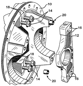
Figure 2 illustrates a carrier assembly 10 and pilot web 12 according to the
present invention. The pilot web of the present invention can be utilized to
support the
pilot bearing of the pinion that supports the ring gear of the differential.
As illustrated,
the carrier assembly 10 and pilot web 12 are formed as separate pieces. As
shown in
the illustrated embodiment of the present invention, preferably four mounting
bolts 14
are provided to secure the pilot web to the carrier assembly. When four
mounting bolts
CA 02543178 2006-04-21
WO 2005/045283 PCT/US2004/035184
are used, they are disposed in pairs to mount the pilot web 12 to the carrier
assembly
10. The mounting bolts 14 pass through holes 16 in the pilot web 12 and into
holes 18
in the carrier assembly 10, to secure the pilot web 12 to the carrier assembly
10.
In service, loads of the pinion reacted through the pilot bearing can cause
shear
loads which can cause the mounting bolts 14 to loosen from the carrier
assembly 10.
Therefore, as a feature of the present invention, it has been found that
bushings 20 or
dowel bushings are preferably disposed about either two or four of the
mounting bolts
14. The bushings serve to lock the pilot web 12 into position with the carrier
assembly
and to absorb a great deal of the lateral forces. This addresses the concerns
10 regarding the shear forces and helps secure the assembly of the pilot web
12 to the
carrier assembly 10 under load. If there are two bushings 20 used, they would
preferably be disposed about mounting bolts 14 on opposing corners, i.e. the
left bolt of
one of the top and bottom pairs, and then the right bolt of the other pair. It
has been
found that two bushings 20, disposed around bolts on opposing corners (one top
and
one bottom), are generally sufficient to overcome the shear forces.
While the current invention envisions the use of two bushings 16, it is also
possible, within the scope of the present invention, to use four bushings 16,
one for
each mounting bolt 14. Preferably, the bushings are made of steel. It is also
preferable
for the holes 16 in the pilot web 12 and the holes 18 in the carrier assembly
10 to each
be counter bored to accept the bushing.
Figure 3 illustrates a hole 16, in the pilot web 12 having a counter bore 26.
As
can be seen in this embodiment, there is only the necessity of one counter
bore 26 in
this end of the pilot web, as this figure illustrates an embodiment of the
invention
utilizing only two bushings 20. In an embodiment utilizing 4 bushings, each of
the
holes would advantageously be counter bored.
Figure 4 illustrates an embodiment of the present invention wherein the pilot
web 12 is again not shown attached to the carrier 10, but is instead shown in
much
closer proximity. The web 12 has a stop 22 which is positioned adjacent to a
stop 24
projecting from the carrier 10. Because there will tend to be deflections of
the structure
under load, with the stop 22 of the carrier deflecting towards the stop 24 of
the web,
these stops 22, 24 must be precision machined to a very high tolerance, to
minimize the
clearance therebetween. A minimal clearance between the stops 22, 24 is
necessary for
assembly. Preferably, the stops are machined so that there is only about a few
CA 02543178 2006-04-21
WO 2005/045283 PCT/US2004/035184
4
thousands of an inch clearance between them. Most preferably, the clearance is
about
0.002" or less between the stops 22, 24. Clearance between the stops 22, 24
results in
bearing reaction forces being transferred from the pilot web 12 into the
carrier
assembly 10, upon the gap being closed when under load. The minimal clearance
between the stops 22, 24 results in the combination of stops essentially
functioning as a
single unit and maximizing the bearing forces transferred. The combination of
precision machined gap between stops 22, 24 and the use of the bushings 20
described
above provides component stiffness approaching that of a pilot web that is
cast directly
onto the carrier.