Note: Descriptions are shown in the official language in which they were submitted.
CA 02543391 2009-06-26
CONNECTOR COUPLING STRUCTURE
Field of the Invention
Devices, systems, and methods consistent with the present invention relate to
a
connector coupling structure for coupling connectors which are used to connect
a wire
harness with accessories, such as audio equipment and vehicular meters, of an
automotive vehicle and the like.
Description of the Related Art
In a conventional example of a connector coupling structure, in which audio
equipment is mounted on an instrument panel of an automotive vehicle, a wire
harness
extends from a power supply to the panel, and the distal end of the wire
harness is
connected to a female connector, which in turn is coupled to a male connector
provided
on the back side of the audio equipment. A coupling operation of the male
connector
and the female connector is carried out at a back side of the instrument
panel. After a
completion of the coupling operation, the next operation, i.e., securing the
audio
equipment to the instrument panel is carried out. As described, such a
conventional
structure inevitably involves a two-step operation, and therefore, working
efficiency is
decreased. Moreover, a problem arises in which the wire harness has a slack
due to a
margin of the length thereof after installation of the audio equipment whereby
abnormal
1
CA 02543391 2006-04-13
noise is produced.
Therefore, structures have been developed in which positional deviation
between
a male connector and a female connector is absorbed by the connectors
themselves in
order to increase assemble-ability thereof and to realize an easy and reliable
connection
between the connectors. One of the structures is formed of a female connector
and a
male connector. The female connector consists of a housing, a guide for
enabling the
housing to slide, a first columnar projection provided on the guide, and a
second
columnar projection provided on the housing. The male connector consists of a
housing
for the male connector, a lever, terminals for the female connector and
terminals for the
male connector, both provided on the housing for the male connector, and a
guidance
groove for guiding the first columnar projection and the second columnar
projection.
Both housings are coupled by treating the first columnar projection inside the
guidance
groove as a point of action, by treating the second columnar projection as a
power point,
and by moving the housing for the female connector in a connection direction
with
respect to the male connector (see Japanese Patent Application, First
Publication No.
2000-215944 (page 4, Fig. 3)).
The above official publication discloses a male connector which is provided
with two U-shaped levers disposed symmetrically with respect to one another,
each
lever consists of plate portions extending parallel with one another, the
plate portions of
the each lever are coupled to an upper surface and a lower surface of the male
connector
at one end side of each of the plate portions and are connected to one another
at the
opposite end side of the plate portions. With lever grooves formed on each
lever along
which the first columnar projection and the second columnar projection are
guided, both
connectors are coupled to one another. The levers which function as a cam are
structurally important. In the conventional structure, such a cam or levers
are essential
2
CA 02543391 2009-06-26
parts, and therefore, there become a number of parts to be assembled, thus
resulting in
increased cost of production. Further, another problem arises in which the
degree of
freedom in design of modules is low, since such a cam or levers are
substantially large.
SUMMARY OF THE INVENTION
In consideration of the above circumstances, an object of the present
invention is
to provide a new connector coupling structure which does not have such a
conventional
lever and which is somewhat down-sized and manufactured at low cost, and
enables a
three-dimensional alignment in three directions of X, Y and Z axes to increase
the
degree of freedom in the design of modules.
Certain exemplary embodiments can provide a connector coupling structure
comprising: a first connector including a housing and a plurality of terminal-
inserting
holes; a second connector including a housing and a plurality of terminals
which are
connectable to said plurality of terminal-inserting holes; a raised portion
which is formed
at a front end side of an inner surface of the second connector housing,
wherein, when
the first and second connectors are coupled, the raised portion is in contact
with an outer
surface of the first connector housing such that a clearance is formed between
the outer
surface of the first connector housing and an inner surface portion other than
the raised
portion of the second connector housing; an inner case which is slidably
received in one
of the first connector housing and the second connector housing and which
includes one
of the plurality of terminal-inserting holes and the plurality of terminals; a
projecting
portion which is formed on a side of the inner case; and a notching piece
which is
formed on said one of the first connector housing and the second connecting
housing and
3
CA 02543391 2009-06-26
which includes a pawl releasably engageable with the projecting portion;
wherein, when
the plurality of terminals and the plurality of terminal-inserting holes are
connected with
one another, the inner case is slid while allowing the notching piece to
resiliently deform
outwardly into the clearance, and the engagement of the pawl and the
projecting portion
is released, then the sliding of the inner case is completed.
Certain exemplary embodiments can provide a connector coupling structure
comprising: a first connector including a housing and a plurality of terminal-
inserting
holes; a second connector including a housing and a plurality of terminals
which are
connectable to said plurality of terminal-inserting holes; an inner case which
is slidably
received in one of the first connector housing and the second connector
housing and
which includes one of the plurality of terminal-inserting holes and the
plurality of
terminals; a U-shaped spring piece which is provided on a side of the inner
case; a rib
which is provided on said one of the first connector housing and the second
connector
housing, and is releasably engageable with the U-shaped spring piece, wherein,
when the
rib is engaged with the U-shaped spring piece, sliding movement of the inner
case in said
one of the first connector housing and the second connector housing is
stopped; a
channel which is provided on a side of the other connector housing of the
first and
second connector housings and which guides a movement of the rib and the U-
shaped
spring piece; and a deflection permitting window which is provided partway
along the
channel and which receives a resiliently deformable portion of the U-shaped
spring
piece; wherein, when said one of said first connector housing and said second
connector
housing, in which the inner case has been partway received, and said other
connector
housing are fitted to each other, the U-shaped spring piece of the inner case
comes to a
position corresponding to the deflection permitting window in such a manner
that the
3a
CA 02543391 2009-06-26
deflection permitting window makes the U-shaped spring piece open to release
an
engagement of the rib such that a fitting degree of both connector housings is
enlarged.
Certain exemplary embodiments can provide a connector coupling structure
comprising: a female connector housing; a male connector housing; wherein,
when said
female and male connector housings are coupled, a clearance is formed between
the
outer surface of the female connector housing and an inner surface of the male
connector
housing; an inner case slidably receivable in one of said female and male
connector
housings; a projecting portion formed on a side of the inner case; and a
notching piece
formed on said one of said female and male connector housings, said notching
piece
having a pawl releasably engageable with the projecting portion of said inner
case,
wherein, when said female and male connectors are coupled, the inner case is
slid while
allowing the notching piece to resiliently deform outwardly into the
clearance, and the
engagement of the pawl and the projecting portion is released then the sliding
of the
inner case is completed.
Certain exemplary embodiments can provide a connector coupling structure
comprising: a female connector housing; a male connector housing; an inner
case
slidably receivable in one of said female connector housing and said male
connector
housing; a U-shaped spring piece provided on a side of the inner case; a rib
provided on
said one of said female connector housing and said male connector housing,
releasably
engageable with the U-shaped spring piece, wherein when the rib is engaged
with the
U-shaped spring piece, sliding movement of the inner case in said one of said
female
connector housing and said male connector housing is stopped; a channel
provided on
the other of said one of said female connector housing and said male connector
housing,
which guides a movement of the rib and the U-shaped spring piece; and a
deflection
3b
CA 02543391 2009-06-26
permitting window which is provided on the channel and which receives a
resiliently
deformable portion of the U-shaped spring piece, wherein when said male and
female
connector housings are fitted to each other, the deflection permitting window
allows the
U-shaped spring piece to open to release an engagement of the rib so that a
fitting degree
of the male and female connector housings is enlarged.
Other embodiments provide a connector coupling structure having: a first
connector
including a housing and a plurality of terminal-inserting holes; a second
connector
including a housing and a plurality of terniinals which are connectable to
their respective
terminal-inserting holes; a raised portion which is formed at a front end side
of an inner
surface of the second connector housing, wherein, when the first and second
connectors
are coupled, the raised portion is in contact with an outer surface of the
first connector
housing such that a clearance is formed between the outer surface of the first
connector
housing and an inner surface portion other than the raised portion of the
second
connector housing; an inner case which is slidably received in one connector
housing of
the first connector housing and the second connector housing and which
includes one of
the plurality of terminal-inserting holes and the plurality of terminals; a
projecting
portion which is formed on a side of the inner case; and a notching piece
which is
formed on said one connector housing and which includes a pawl releasably
engageable
with the projecting portion; wherein, when the plurality of terminals and the
plurality of
3c
CA 02543391 2009-06-26
terminal-inserting holes are connected with one another, the inner case is
slid such that
the engagement of the pawl and the projecting portion is released.
Preferably, the first connector is a female connector and the second connector
is
a male connector.
Further, preferably, the inner case includes the plurality of terminal-
inserting
holes and is slidably received in the first connector housing.
Still further, preferably, when the housing of the first connector is mounted
to a
panel through an opening of the panel, the housing includes a housing body
portion,
which does not pass through the opening of the panel but is engaged with one
surface of
the panel, and a plurality of spring pieces, which are resiliently deformable
so as to pass
through the opening and are resiliently engaged with an other surface of the
panel.
Yet fiu-ther, preferably, when the housing of the second connector is mounted
to
a panel through an opening of the panel, the housing includes a housing body
portion,
which does not pass through the opening of the panel but is engaged with one
surface of
the panel, and a plurality of spring pieces, which are resiliently deformable
so as to pass
through the opening and are resiliently engaged with an other surface of the
panel.
Another object of the present invention is to provide a new connector coupling
structure which does not have such a conventional bulky cam member and which
is
somewhat down-sized and can be manufactured at low cost, and enables an
efficient
absorption of error in a fitting direction.
Other embodiments provide a connector coupling structure having: a first
connector including a housing and a plurality of terminal-inserting holes; a
second connector
including a housing and a plurality of terminals which are connectable to
their respective
temiinal-inserting holes; an inner case which is slidably received in one
connector
4 ,
CA 02543391 2006-04-13
housing of the first connector housing and the second connector housing and
which
includes one of the plurality of terminal-inserting holes and the plurality of
terminals;
and a U-shaped spring piece which is provided on a side of the inner case; a
rib which is
provided on said one connector housing and is releasably engageable with the U-
shaped
spring piece, wherein, when the rib is engaged with the U-shaped spring piece,
sliding
movement of the inner case in said one connector housing is stopped; a channel
which
is provided on a side of the other connector housing of the first and second
connector
housings and which guides a movement of the rib and the U-shaped spring piece;
and a
deflection permitting window which is provided partway along the channel and
which
receives a resiliently deformable portion of the U-shaped spring piece;
wherein, when
said one connector housing, in which the inner case has been partway received,
and said
the other connector housing are fitted to each other, the U-shaped spring
piece of the
inner case comes to a position corresponding to the deflection permitting
window in
such a manner that the deflection permitting window makes the U-shaped spring
piece
open to release an engagement of the rib such that a fitting degree of both
the connector
housings is enlarged.
Preferably, the first connector is a female connector and the second connector
is
a male connector.
Further, preferably, the inner case includes the plurality of terminal-
inserting
holes and is slidably received in the first connector housing.
Still further, preferably, when the housing of the first connector is mounted
to a
panel through an opening of the panel, the housing includes a housing body
portion,
which does not pass through the opening of the panel but is engaged with one
surface of
the panel, and a plurality of spring pieces, which are resiliently deformable
so as to pass
through the opening and are resiliently engaged with an other surface of the
panel.
CA 02543391 2006-04-13
Yet further, preferably, when the housing of the second connector is mounted
to
a panel through an opening of the panel, the housing includes a housing body
portion,
which does not pass through the opening of the panel but is engaged with one
surface of
the panel, and a plurality of spring pieces, which are resiliently deformable
so as to pass
through the opening and are resiliently engaged with an other surface of the
panel.
The above and still further objects, features and advantages of the present
invention will become apparent upon consideration of the following detailed
description
of specific embodiments thereof, particularly when taken in conjunction with
the
accompanying drawings wherein like reference numerals in the various figures
are
utilized to designate like components.
BRIEF DESCRIPTION OF THE DRAWINGS
The above features and advantages of the invention will become more apparent
by describing in detail exemplary embodiments thereof with reference to the
attached
drawings in which:
Fig. 1 is a perspective view illustrating a panel before coupling connectors,
as
viewed from a back side of the panel, according to a first embodiment of the
present
invention.
Fig. 2 is a perspective view illustrating the panel before coupling the
connectors,
as viewed from a front side of the panel.
Fig. 3 is a perspective view illustrating a coupling state.
Fig. 4 is a cross sectional view diagrammatically illustrating the connectors
before coupling thereof.
Fig. 5 is a cross sectional view diagrammatically illustrating a state at the
beginning of insertion of one housing into another housing.
6
CA 02543391 2006-04-13
Fig. 6 is a cross sectional view diagrammatically illustrating the middle of
the
insertion.
Fig. 7 is a cross sectional view diagrammatically illustrating a cancellation
of a
provisional securement.
Fig. 8 is a cross sectional view diagrammatically illustrating a coupling
state.
Fig. 9 is a perspective view illustrating a panel before coupling the
connectors,
as viewed from a back side of the panel, according to a second embodiment of
the
present invention.
Fig. 10 is a perspective view illustrating the panel before coupling the
connectors, as viewed from a front side of the panel.
Fig. 11 is a cross sectional view diagrammatically illustrating the connectors
before coupling thereof.
Fig. 12 is a cross sectional view diagrammatically illustrating a state at the
beginning of insertion of one housing into another housing.
Fig. 13 is a cross sectional view diagrammatically illustrating the middle of
the
insertion.
Fig. 14 is a cross sectional view diagrammatically illustrating a cancellation
of a
provisional securement.
Fig. 15 is a cross sectional view diagrammatically illustrating a coupling
state.
Fig. 16 is a side cross sectional view illustrating deformation permitting
windows and U-shaped spring pieces.
Fig. 17 is a side cross sectional view, which is similar to Fig. 16,
illustrating the
cancellation of the provisional securement implemented by the U-shaped spring
pieces.
7
CA 02543391 2006-04-13
DETAILED DESCRIPTION OF THE INVENTION
Exemplary embodiments of the invention will now be described below with
reference to the attached Figures. The described exemplary embodiments are
intended
to assist the understanding of the invention, and are not intended to limit
the scope of
the invention in any way.
First Embodiment
Hereinafter, a first embodiment according to the present invention will be
exemplarily described with reference to Figs. 1 through 8.
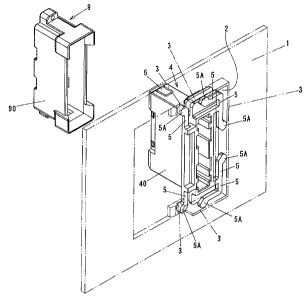
Fig. 1 is a view illustrating a securement state of a female connector 4 with
respect to a panel 1, such as an instrument panel or the like, to which one
connector is to
be secured, when viewed from the back of the panel 1. The panel 1 is formed
with an
opening 2, in which the female connector 4 is mounted. A catching wa113 is
formed
along the periphery of the opening 2 at a panel back side. This catching wall
3 is
comprised of a portion that is formed in such a manner as to protrude from a
back
surface of the panel 1, and of a peripheral wall that is flush with the
opening 2. On a
back surface of the female connector 4 is formed a plurality of spring pieces
5, each of
which has a tip 5A that is an outwardly rounded bulging portion. Each of the
tips 5A
(or rounded bulging portions) of the spring pieces 5 is brought into resilient
contact with
the aforesaid catching wall 3 whereby the female connector 4 is secured to the
panel 1.
The tips 5A of the spring pieces 5 bulge in such a manner as to protrude
outwardly from
outlines by which the back surface of the female connector 4 is defined. Under
a state
in which the tips 5A of the spring pieces 5 are in resilient contact with the
catching wall
3, positioning control of the female connector 4 in X and Y axial directions
is possible.
When a housing 40 of the female connector 4 is molded from a resin material,
the
aforesaid spring pieces 5 are also integrally formed with the housing 40. The
spring
8
CA 02543391 2006-04-13
pieces 5 are provided on a rectangular-shaped back surface of the female
connector 4,
one at each short side (or each of upper and lower sides) of the rectangular
shape and
two at each long side (or each of left and right sides) of the rectangular
shape.
Further, notching pieces 6 with C-shaped incisions formed thereon are
provided,
one at each of top and bottom portions of a front side of the housing 40 of
the female
connector 4. An inner case 8 with a number of terminal-inserting holes 7, as
more
fully discussed hereinafter, is housed in the housing 40 so as to be slidable
therein.
This inner case 8 is provisionally secured in position by means of pawls 11
that are
formed in the notching pieces 6 (details thereof will be described
hereinafter).
A male connector 9 is fitted in the female connector 4. In Fig. 1, a number of
male terminals 10 to be inserted in their respective terminal-inserting holes
7 are not
illustrated, and instead, a housing 90 to house those male terminals 10 is
only illustrated.
This housing 90 is fitted on the aforesaid housing 40 so as to cover thereof.
The male
connector 9 is provided at a back side of accessories such as vehicular
meters.
Fig. 2 is a view illustrating the panel 1, as viewed from a front side
thereof. As
described, the inner case 8 is provided with the number of terminal-inserting
holes 7,
and with a number of female terminals each being inserted in one of the
terminal-inserting holes 7 and connected with a wire harness extending from a
power
supply. By inserting the male terminals 10 of the male connector 9 disposed at
the
back side of the accessories, in the terminal-inserting holes 7, the
mechanical coupling
between the two connectors, i.e., the female connector 4 and the male
connector 9 is
carried out. Such a coupling state is illustrated in Fig. 3.
Now, coupling operation of said connectors 4 and 9 will be described
hereinafter
with reference to Fig. 4 and subsequent figures. The pawls 11 are provided
inside the
notching pieces 6, as described above, and the aforesaid inner case 8 is
formed with
9
CA 02543391 2006-04-13
projecting portions 12. Fig. 4 illustrates a state in which the pawls 11 and
the
projecting portions 12 are engaged with one another. This state is a state in
which the
inner case 8 is provisionally secured in position in the housing 40 of the
female
connector 4. As long as this provisional securement is not released, the inner
case 8
does not slide in the housing 40. Further, raised portions 13, which are
formed at a
front end side of an inner surface of the housing 90, touch an outer surface
of the
housing 40 with a clearance 14 formed between the inner surface of the housing
90 and
the outer surface of the housing 40. A structure is preferable in which a
raised portion
13 is formed along the whole periphery of the inner surface of the housing 90.
However, another structure is sufficient in which raised portions are formed
on the inner
surface of the housing 90 each at a location which corresponds to a location
of one of
the corresponding notching pieces 6. At the time the projecting portions 12
are moved
over the pawls 11 of the notching pieces 6, front end portions of the notching
pieces 6
are outwardly resiliently deformed or extended. As such, in order to
sufficiently
receive such deformations or extensions, there is a need to provide the
corresponding
clearance 14 formed inside the housing 90.
Referring to Figs. 5 and 6, when the male terminals 10 are inserted in the
terminal-inserting holes 7, an offset in the X and Y directions is controlled
by means of
the spring pieces 5, such that the male terminals 10 are inserted in the
proper position.
Fig. 5 illustrates a state in which the male terminals 10 are correctly
inserted in the
terminal-inserting holes 7. From thence, the male connector 9 is further
inserted and
advanced with respect to the female connector 4. A support member 15, by which
the
male terminals 10 are supported, then abuts against the inner case 8 at a
front surface
thereof. At this time, the advancement of the inner case 8 is temporarily
stopped due
to an engagement of the projecting portions 12 of the inner case 8 with the
pawls 11.
CA 02543391 2006-04-13
When the male terminals 10 are inserted in the terminal-inserting holes 7,
because the
inner case 8 is in the provisional securing state as described above, the
insertion
operation as well as two (X and Y) dimensional adjustment are rendered to be
easy.
Thereafter, the male connector 9 is further advanced or moved. At this time,
as
illustrated in Fig. 7, the projecting portions 12 of the inner case 8 ride
over the pawls 11
of the notching pieces 6 whereby the front end portions of the notching pieces
6 are
outwardly resiliently deformed so that they are received in the clearance 14.
The male
connector 9 is further advanced or moved until the support member 15 abuts
against an
end of the housing 40 and thereby stops. Fig. 8 illustrates a state in which
the male
connector 9 is advanced or inserted to the full extent with respect to the
female
connector 4. The female connector 4 is slid or moved by a length L from a
position
corresponding to the provisional securing state, as shown in Fig. 6, to a
position
corresponding to a coupling-completion state, as shown in Fig. 8. In a case
where the
connector 9 is inserted so deep in the above position, adjusting thereof is
possible by
pulling the connector 9.
Second Embodiment
Hereinafter, a second embodiment according to the present invention will be
described with reference to Figs. 9 through 17.
Fig. 9 is a view illustrating a securement state of a female connector 104
with
respect to a panel 101, such as an instrument panel or the like, to which one
connector is
to be secured, when viewed from back of the panel 101. The panel 101 is formed
with
an opening 102, in which the female connector 104 is mounted. A catching wall
103 is
formed along the periphery of the opening 102 at a panel back side. This
catching wall
103 is comprised of a portion that is formed in such a manner as to protrude
from a back
surface of the panel 101, and of a peripheral wall that is flush with the
opening 102.
11
CA 02543391 2006-04-13
On a back surface of the female connector 104 is formed a plurality of spring
pieces 105,
each of which has a tip 105A that is an outwardly rounded bulging portion.
Each of
the tips 105A (or rounded bulging portions) of the spring pieces 105 is
brought into
resilient contact with the aforesaid catching wall 103 whereby the female
connector 104
is secured to the panel 101. The tips 105A of the spring pieces 105 bulge in
such a
manner as to protrude outwardly from outlines by which the back surface of the
female
connector 104 is defined. Under a state in which the tips 105A of the spring
pieces
105 are in resilient contact with the catching wall 103, positioning control
of the female
connector 104 in X and Y axial directions is possible. When a housing 140 of
the
female connector 104 is molded from a resin material, the aforesaid spring
pieces 105
are also integrally formed with the housing 104. The spring pieces 105 are
provided
on a rectangular-shaped back surface of the connector 104, one at each short
side (or
each of upper and lower sides) of the rectangular shape and two at each long
side (or
each of left and right sides) of the rectangular shape.
Further, ribs 106 are provided one at a center position of each of top and
bottom
portions of a front side of the housing 140 of the female connector 104, each
rib
extending in a back and forth direction as shown in Fig. 9. An inner case 108
with a
number of terminal-inserting holes 107, as more fully discussed hereinafter,
is housed in
the housing 140 so as to be slidable. U-shaped spring pieces 110 are provided,
one at
each side of the inner case 108, to latchingly engage the ribs 106. The
advancement or
insertion of the inner case 108 within the housing 140 is temporarily stopped
due to a
latching engagement of these U-shaped spring pieces 110 with the ribs 106.
Namely,
the inner case 108 is provisionally secured in position within the housing
140. Each of
the U-shaped spring pieces 110 has a break consisting of opposed portions, a
length
between which is shorter than a width of each of the ribs 106. When a leading
end of
12
CA 02543391 2006-04-13
the rib 106 is pushed through the break or opposed portions of the U-shaped
spring
piece, a force is necessary for compulsorily widening the break of the U-
shaped spring
piece 110.
A male connector 109 is fitted in the female connector 104. In Fig. 9, a
number of male terminals 112 to be inserted in their respective terminal-
inserting holes
107 are not illustrated, and instead, a housing 190 to house those male
terminals 112 is
only illustrated. This housing 190 is fitted on the aforesaid housing 140 in
such a
manner as to cover the housing 140. The male connector 109 is provided at a
back
side of accessories such as vehicular meters. Channels 111 A are formed, one
at each
side of the housing 190. The ribs 106 and the U-shaped spring pieces 110 are
inserted
in the channels 111 A in such a manner as to slide. The housing 190 is
provided with
deflection permitting windows 111 which are formed at intermediate positions
of the
channels l 11 A and which enable the break of the U-shaped spring piece 110 to
be
widened in right and left directions when the inner case 108 is inserted in
the channel
111A so that the rib 106 enters the break of U-shaped spring piece. The
deflection
permitting windows 111 are structured as follows. Figs. 9 and 16 indicate a
provisional securing state in which the leading end of the rib 106 abuts
against the break
of the U-shaped spring piece or a latching engagement of the inner case 108
and the
housing 140 is formed. When the U-shaped spring piece 110 occupies a position
corresponding to the U-shaped spring piece, the opposed portions (or break) of
the
U-shaped spring piece 110 are widened from side to side by a forcible
insertion of the
rib 106 in the break of the U-shaped spring piece 110. As seen from the
foregoing, the
deflection permitting window 111 enables the connectors 104 and 109 to be
reliably
connected to one another, when the housing 140 is further deeply inserted in
the
housing 190. Further, the deflection permitting window 111 contributes to
absorption
13
CA 02543391 2006-04-13
of an in-depth error.
Fig. 10 is a view illustrating the panel 101, as viewed from a front side
thereof.
As described, the inner case 108 is provided with the number of terminal-
inserting holes
107, and with a number of female terminals each being inserted in one of the
terminal-inserting holes and connected with a wire harness extending from a
power
supply. By inserting the male terminals 112 of the male connector 109 disposed
at the
back side of the accessories, in the terminal-inserting holes 107, the
mechanical
coupling between the two connectors, i.e., the female connector 104 and the
male
connector 109 is carried out. Additionally, pawls 140A formed on the housing
140
engage and disengage with respect to unillustrated projections which are
provided on
the inner case 108.
Now, coupling operation of the connectors 104 and 109 will be described
hereinafter with reference to Fig. 11 and subsequent figures. Fig. 11
illustrates a state
in which the ribs 106 and the U-shaped spring pieces 110 are engaged with one
another.
This state is a state in which the inner case 108 is provisionally secured in
position in
the housing 140 of the female connector 104. As long as this provisional
securement
is not canceled, the inner case 108 does not slide in the housing 140.
Further, an
insertion opening of the housing 190 is formed with a tapered opening 190A
which has
a diameter widened, and also formed with a bottom portion 190B against which
the
inner case 108 abuts.
Referring now to Figs. 12 and 13, when the male terminals 112 (not shown in
the drawings) are inserted in the terminal-inserting holes 107, an offset in
the X and Y
directions is controlled by means of the spring pieces 105, such that the male
terminals
112 are inserted in the proper position. Fig. 12 illustrates a state in which
the male
terminals 112 are correctly inserted in the terminal-inserting holes 107. From
thence,
14
CA 02543391 2006-04-13
the male connector 109 is further inserted and advanced with respect to the
female
connector 104. At this time, the advancement of the inner case 108 is
temporarily
stopped due to an engagement of the ribs 106 of the housing 140 with the U-
shaped
spring pieces 110. When the male terminals 112 are inserted in the terminal-
inserting
holes 107, because the inner case 108 is in the provisional securing state as
described
above, insertion operation as well as two (X and Y) dimensional adjustment are
rendered to be easy. Thereafter, the male connector 109 is further advanced or
moved.
At this time, as illustrated in Fig. 14, the U-shaped spring pieces 110 are
outwardly
resiliently deformed against their spring forces such that they are received
in the
deflection permitting window 111 in such a manner that they are disengaged
from the
ribs 106. The male connector 109 is further advanced or moved so as to present
a state
as described in Fig. 15. In a case where the connector 109 is inserted so deep
or in the
above-described position, adjusting thereof is possible by pulling the
connector 109.
In Fig. 15, E indicates an absorbable amount of error in the insertion
direction.
Figs. 16 and 17 are cross sectional side views illustrating the relationship
between the deflection permitting windows 111 and the U-shaped spring pieces
110.
While the invention has been particularly shown and described with reference
to
exemplary embodiments thereof, the present invention is not limited to these
embodiments. It will be understood by those of ordinary skill in the art that
various
changes in fozm and details may be made therein without departing from the
spirit and
scope of the invention as defined by the following claims.