Note: Descriptions are shown in the official language in which they were submitted.
CA 02543460 2009-07-15
CROSSOVER TWO-PHASE FLOW PUMP
Field of the Invention
This invention relates in general to well pumps and in particular to a pump
for
pumping a well fluid containing a mixture of liquid and gaseous fluids.
CA 02543460 2006-04-13
Background of the Invention
A common system for pumping large volumes of fluid from a hydrocarbon well
employs an electrical submersible pump assembly. The pump assembly includes a
centrifugal pump and a down hole electrical motor. The pump is made up of a
large
number of pump stages, each pump stage having an impeller and a diffuser. The
impeller
rotates and imparts velocity to the well fluid while the diffuser converts the
kinetic
energy to pressure.
Pumps of this type efficiently pump liquids, but many hydrocarbon wells
produce
both liquid and gas. Efficiently pumping two-phase fluids with a centrifugal
pump is
difficult if the density difference between the two phases is significant. The
impeller
stages of a centrifugal pump increase the pressure by imparting velocity to
the fluid. The
pressure that is created is a function of the density of the fluid. For
example, if the liquid
components of the well fluid had a density 100 times greater than the gaseous
components, the gas would require ten times more velocity to achieve the same
pressure
as the liquid. Oil has approximately 100 times the density of natural gas at
approximately
150 psi. An impeller of a centrifugal pump cannot accomplish the differences
in velocity,
resulting in the lighter fluid gathering in pockets near the center of
rotation. These
pockets have great difficulty in moving into the area of high pressure, and
therefore grow
larger, blocking the flow area and reducing the pressure creation ability of
the pump stage
until it has been reduced to the point where the gas can move.
One approach to solve the problem of gas content in hydrocarbon well fluid is
to
utilize a gas separator. The gas separator locates below the pump and
separates gas from
HOU5TOIVU 830845.1 2
CA 02543460 2006-04-13
the liquid, typically by a forced vortex. The forced vortex forces the heavier
components
to the outer portions of the gas separator housing, leaving the lighter
components near the
axis of rotation. The heavier components have a much higher velocity than the
lighter
components. A crossover at the upper end of the gas separator guides the
heavier fluid
components back into the central area and into the intake of the pump. The
lighter fluid
components are diverted outward from the gas separator into the casing.
HOUSTON\1830845.1 3
CA 02543460 2008-12-22
Summary of the Invention
In this invention, a down hole well pumping apparatus is employed that has a
central rotary pump section configured for pumping the liquid or heavier
components.
An annular turbine section surrounds the pump section. The turbine section has
blades
for compressing the gaseous components.
A cyclindrical wall separates the pump section from the turbine section. The
rotatable components of the pump section and the turbine section preferably
rotate in
unison. The pump thus increases the pressure of both the heavier and the
lighter
components.
Accordingly, in one aspect of the present invention there is provided an
apparatus for pumping a well fluid containing gaseous and liquid components,
comprising:
a central rotary pump section for pumping the liquid components, the pump
section comprising a plurality of pump stages, each pump stage comprising an
impeller
and a pump diffuser, the impeller of each pump stage being rotatable relative
to the
pump diffuser of each pump stage;
an annular turbine section having a plurality of turbine stages surrounding
the
pump section for compressing the gaseous components, each of the turbine
stages
comprising a plurality of rotatable turbine blades and a turbine diffuser, the
turbine
blades being rotatable relative to the turbine diffuser;
a housing containing the turbine section and the pump section;
a separating device in the housing upstream of the turbine section and the
pump
section for separating well fluid flowing into the housing into an outer
portion and an
inner portion, the outer portion containing more liquid components than the
inner
4
CA 02543460 2008-12-22
portion, and the inner portion containing more gaseous components than outer
portion;
and
a cross-over device downstream of the separating device and upstream of the
turbine section and the pump section for guiding the outer portion of the well
fluid into
the pump section and guiding the inner portion of the well fluid into the
turbine section.
According to another aspect of the present invention there is provided an
apparatus for pumping a well fluid containing gaseous and liquid components,
comprising:
a housing having a longitudinal axis;
a rotatably driven shaft extending through the housing;
a plurality of impellers mounted to the shaft for rotation therewith, each of
the
impellers having a central section for receiving liquid components of the well
fluid from
the central portion of the housing and an outer section portion for receiving
gaseous
components of the well fluid;
a cylindrical wall in each impeller separating the central section from the
outer
section, the central section of each impeller containing at least one
helically extending
impeller passage configured for pumping substantially liquid and the outer
section of
each impeller containing a plurality of blades configured for compressing gas;
a diffuser mating with each impeller, each of the diffusers being mounted in
the
housing, each of the diffusers having a central section that registers with
the central
section of one of the impellers and an outer section that registers with the
outer section of
one of the impellers;
a cylindrical inner wall in each of the diffusers that separates the central
section
from the outer section; and
4a
CA 02543460 2008-12-22
a cylindrical outer wall surrounding the outer section of each of the
diffusers, the
cylindrical outer walls of the diffusers engaging the housing and being
stacked together
to prevent rotation of the diffusers, wherein the outer section of the
diffuser has a
plurality of diffuser passages configured to convert kinetic energy of the
gaseous
components flowing from the outer section of a mated impeller into a greater
pressure.
According to yet another aspect of the present invention there is provided a
method for pumping a well fluid from a well containing gaseous and liquid
components,
comprising:
(a) mounting an annular turbine section around a central rotary pump
section;
(b) deploying the turbine section and the pump section in the well and
rotating the turbine section and the pump section;
(c) causing a stream of well fluid containing a mixture of liquid and gas
components to flow toward the turbine section and the pump section and prior
to
reaching the turbine section and the pump section, separating the stream into
an outer
portion and an inner portion, the outer portion containing more liquid
components than
the inner portion, and the inner portion containing more gaseous components
than the
outer portion;
(d) delivering the outer portion of the flow stream to the pump section and
pumping the outer portion of the flow stream with the pump section; and
(e) delivering the inner portion of the flow stream to the turbine section and
compressing the gaseous components within the inner portion of the flow stream
with the
turbine section.
4b
CA 02543460 2006-04-13
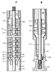
Brief Description of the Drawines
Figures 1A and 1B comprise a vertical sectional view of a pump assembly
constructed in accordance with this invention.
Figure 2 is a top view of one of the impellers of the pump assembly of Figure
1.
Figure 3 is a side view of the impeller of Figure 2, with portions sectioned
to
illustrate the impeller auger flights.
Figure 4 is a sectional view of one of the turbine blades of the impeller of
Figure
2, taken along the line 4- -4 of Figure 2.
Figure 5 is a quarter sectional view of a portion of the impeller of Figure 2.
Figure 6 is a sectional view of a diffuser of the pump of Figures IA and 1B.
Figure 7 is a top view of the diffuser of Figure 6.
Figure 8 is a vertical sectional view of the impeller of Figure 2 assembled
with the
diffuser of Figure 6.
Figure 9 is a schematic elevational view of the pump of Figure 1 incorporated
within a pump assembly in a well.
.., , . . ..
HOUSTON\I 830845.1 5
CA 02543460 2006-04-13
Detailed Description of the Preferred Embodiment
Referring first to Figure 9, a well has a casing 11 containing perforations
(not
shown) for admitting formation fluid. An electrical submersible pump assembly
13 is
suspended in casing 11 on a string of tubing 15. Tubing 15 may comprise
sections of
production tubing secured together. Alternately, tubing 15 may comprise a
continuous
string of coiled tubing. Well fluid pumped by ESP assembly 13 flows up tubing
15, but it
could alternately be configured to flow up the annulus surrounding tubing 15
within
casing 11.
Pump 17 is secured to tubing 15 and has an intake 19 for drawing in well
fluid. A
seal section 21 connects the lower end of pump 17 to motor 23. Seal section 21
reduces
the pressure differential between the lubricant in motor 23 and the
hydrostatic pressure of
the well fluid in casing 11. A power cable 25 extends from the surface to
motor 23 for
supplying electrical power.
Referring to Figures lA and 1B, pump 17 has a tubular housing 27. Housing 27
.includes a discharge adapter 29 at its upper end. The particular adapter 29
shown is a
type that would be used to connect pump 17 to another pump (not shown) in
tandem.
Adapter 29 could alternately be configured for connection to tubing 15 (Fig.
1).
Discharge adapter 29 has a discharge passage 31. As shown in Figure 1B,
housing 27
also includes an intake adapter 33 on its lower end. Intake adapter 33 has
intake ports 35
and connects to seal section 21 (Fig. 9).
HOUSTON\I830845.] 6
CA 02543460 2006-04-13
A shaft 37 extends through housing 27. Shaft 37 is supported by bearings 38a,
38b, and 38c. Shaft 37 is shown having a splined upper end, which would be
used in
case pump 17 is connected in tandem to another pump. Altemately, the upper end
of
shaft could terminate without a splined end, in which case an adapter for
connecting
pump 17 to tubing 15 would be employed. A coupling 39 on the lower end of
shaft 37
connects shaft 37 to a shaft of seal section 21, which in turn is rotated by
the shaft of
motor 23 (Fig. 9).
In this embodiment, an inducer 41 is located at the lower end of pump 17 above
intake ports 35. Inducer 41 is optional and in this embodiment comprises a
helical vane
that rotates with shaft 37, serving as an auger. A gas/liquid separator is
located above
inducer 41. The separator could be of a variety of types and preferably is a
forced vortex
type that uses centrifugal force to cause a separation of the lighter and
heavier
components of the well fluid. Alternately, a passive device of a type that
creates a
swirling motion of the upward flowing well fluid might be suitable in some
cases. The
gas separator shown includes a set of blades or vanes 45 that rotate with
shaft 37 to
impart centrifugal force to the well fluid. Vanes 45 cause heavier and lighter
components
of the well fluid to separate. The heavier components flow to the outer
annular area
while the lighter components remain in a central area near shaft 37.
Preferably, an
annular separation chamber 46 extends above rotor vanes 45 to provide room for
the
separation to occur. In this example, separation chamber 46 is passive and
free of any
structure other than shaft 37. Alternately, rather than an empty chamber 46,
rotor vanes
45 could be located within an upward extending cylinder that also rotates.,
. . . ..,,. , , . , ,.
HOUSTONU 830845.1 7
CA 02543460 2006-04-13
A crossover member 47 at the upper end of chamber 46 has a central inlet 49 in
an annular space surrounding shaft 37. The lighter components, mostly gaseous
fluids,
flow into passage 49, which directs them upward and radially outward. The
annular
space on the exterior of central inlet 49 leads upward and inward to a central
outlet 51
that is in a central area surrounding shaft 37. The heavier components, mostly
liquid,
flow from the outer annular area of separation chamber 46 into the central
outlet 51. In
this embodiment, chamber 46 has a stationary cylindrical liner 52 that extends
within
housing 27 from intake adapter 33 to the upper end of crossover member 47.
Liner 52
may be of a more corrosion resistant material than housing 27 for protecting
the interior
of housing 27.
A'number of pump stages are located in housing 27 between crossover member
47 and upper bearing 38a. Referring to Figure 2, each pump stage has an
impeller 53 that
rotates in unison with shaft 37 (Fig. lA). Impeller 53 has a cylindrical hub
55 that slides
over and is connected to shaft 37 (Fig. lA) by a key. Impeller 53 has a
central section
that registers with crossover outlet 51 (Fig. 1 A) for receiving heavier well
fluid
components. The central section of each impeller 53 has at least one helical
passage
defined by at least one blade or vane configured for pumping primarily liquid.
In the
preferred embodiment, the passage is defined by at least one helical flight
57. In this
example, two helical flights 57 are employed. Each helical flight 57 extends
around hub
55 a circumferential distance of about 180 degrees from a lower edge of
helical flight 57
to an upper edge 59 of helical flight 57. Preferably each flight 57 extends at
least 90
degrees, and if flights 57 extended only 90 degrees, preferably four flights
57,would be
employed. Helical passages for fluid flow are defined by the upper and lower
surfaces of
NOUST'OM 830845.1 8
CA 02543460 2006-04-13
each flight 57. Upper edge 59 of each helical flight 57 lags the inner edge
considering
the direction of rotation.
Also, as shown in Figure 5, optionally each helical flight 57 is conical in
cross-
section from an inner edge 61 to an outer edge 63. Outer edge 63 is located
axially
downstream of inner edge 61 as measured along a radial line extending from the
longitudinal axis. Inner edge 61 joins hub 55 and outer edge 63 joins a
cylindrical
sidewa1165.
Referring again to Figure 2, each impeller 53 has an outer section that
surrounds
sidewall 65. The outer section has a plurality of blades, vanes or passages
configured
primarily for compressing gas. In the preferred embodiment, the outer section
comprises
a plurality of turbine blades 67 mounted to sidewall 65 and protruding outward
therefrom. Each turbine blade 67 is configured for pumping a fluid having
significant
gas content, thus turbine blades 67 may be considered to be gas compressor
blades. Each
turbine blade 67 has an upper edge 69 and a lower edge 71. Lower edge 71 leads
considering the direction of rotation as indicated by the arrow in Figure 2.
Upper edge 69
and lower edge 71 are preferably parallel to each other. Also, upper edge 69
and lower
edge 71 are preferably offset and parallel to a radial line 73. Turbine blades
67 are
preferably concave as illustrated in Figure 4.
Preferably, there are more blades 67 than helical flights 57. In this
embodiment,
seven turbine blades 67 are illustrated, but the number could vary. Turbine
blades 67
rotate in unison with helical flights 57, but at a faster rotational velocity
because of the
. ,. . , . , , ,.
farther distance from the centerline of impeller 53.
HOUSTON\l 830845.1 9
CA 02543460 2006-04-13
Referring to Figures 6 and 7, each pump stage has a diffuser 75 that mates
with
one of the impellers 53 (Figure 2). Diffuser 75 is stationary and has an outer
wall 77 with
a depending portion for receiving a mating impeller 53 within its interior, as
illustrated in
Figure 8. Outer wall 77 contacts and transmits downward thrust to liner 52
(Fig. 1A),
which in turn directs thrust to the lower end of housing 27. Diffuser 75 has
an inner wall
79 that is cylindrical and the same diameter as sidewall 65 (Figure 3) of
impeller 53. A
hub or sleeve 81 locates within the center of each diffuser 75. An upper
extending
portion of impeller hub 55 (Figure 3) extends into sliding engagement with the
inner
diameter of sleeve 81.
A plurality of stationary helical blades 83 extend between sleeve 81 and inner
side
wall 79 as illustrated in Figure 7. Helical blades 83 extend in the opposite
direction from
helical flights 57 of impeller 53 (Figure 2). Helical blades 83 define
diffuser passages
between them for directing fluid upward and radially inward to the next
impeller 53 (Fig.
2). While doing so, the diffuser passages defined by blades 83 slow the
velocity of the
fluid and convert kinetic energy into higher pressure. There are three
diffuser blades 83
in this example, and each extends less than 120 degrees. In this embodiment,
each
diffuser blade, 83 extends circum'ferentially about 70 degrees from a lower
edge 87 to an
upper edge 85, but that could vary.
A plurality of stationary outer blades 89 extend from inner wall 79 to outer
wall
77. In this embodiment, there are six outer blades 89, but that number could
vary. Each
diffuser blade 89 has an upper edge 91 and a lower edge 93. Preferably each
outer blade
89 is concave and inclines in the opposite direction to turbine blades 67
(Fig. 2). Lower
edge 93 is upstream from upper edge 91. Outer blades 89 extend helically to
define
HOUSTON\I 830845.1 10
CA 02543460 2006-04-13
passages between them to convert kinetic energy of the gaseous fluids into
pressure. In
this example, each outer blade 89 extends about 45 degrees measured at the
inner edge
where it joins inner wal179. Other configurations are available.
In operation, ESP assembly 13 is installed in a well. Electrical power is
supplied
over cable 25 to motor 23 to rotate motor 23 at a conventional speed such as
3600 rpm.
Alternately, the speed could be varied by a variable speed drive, but rotation
greater than
3600 rpm is not required. Referring to Figures IA and 1 B, shaft 37 rotates
inducer 41 to
draw well fluid in through intake ports 35. Vanes 45 rotate with shaft 37,
creating a
forced vortex with heavier components flowing outward near liner 52 and
lighter
components remaining near shaft 37. Crossover member 47 reverses the positions
of the
lighter and heavier components of the well fluid stream. The gaseous fluid
flows up
passage 49 into the outer section of the first impeller 53. The heavier
components flow
into the central section of the first impeller 53.
Impellers 53 rotate in unison with shaft 37 while diffusers 75 remain
stationary.
The central pump section of each impeller 53 increases the velocity of the
heavier
components with helical flights 57. Turbine blades 67 of impellers 53 increase
the
velocity of the lighter components. Each diffuser 75 slows the velocities with
inner
blades 83 and outer blades 89. The reduction in velocity increases the
pressures of the
heavier and lighter components and delivers the separate streams to the next
downstream
impeller 53.
The dynamic pressure of the heavier components at each stage likely will
differ
, . , .... , , , . , .
from the dynamic pressure of the gaseous components at the same stage, but the
HOUSTOWl1830845.1 11
CA 02543460 2006-04-13
sidewalls 65 and 79 prevent commingling of the gas and liquid components. The
pressure increases with each pump stage. The well fluid stream exits the
uppermost
pump stage with the lighter components still located outward from the heavier
components. These components could both flow into common discharge 31 and from
there through tubing 15 (Figure 9) to the surface. If so, the fluids would be
free to
conuningle within common discharge 31 and tubing 15. Alternately, the
separated gas
could be directed out of housing 27 into the casing annulus surrounding tubing
15 or to a
separate conduit extending to the surface.
The invention has significant advantages. The separate inner and outer
sections
of the impellers and diffusers are configured for pumping liquid and gaseous
fluids,
respectively. Because the outer section is configured for compressing gas, gas
pockets do
not develop in the central section, which otherwise tend to block the pumping
of liquids.
Because the outer section rotates faster than the central section, the outer
section vanes
and diffuser blades are able to efficiently compress the gas. The helical
flight or flights
are able to efficiently pump the liquid even though the rotational speed is
slower in the
inner section. If desired, both the heavier and lighter liquids can be
conveyed up the
tubing from the pump. The sidewalls between the central and outer sections of
the
impellers and diffusers prevent commingling within the pump.
While the invention has been shown in only one of its forrns, it should be
apparent
to those skilled in the art that it is not so limited but is susceptible to
various changes
without departing from the scope of the invention. For example, a continuous
helical
flight could be utilized in the central section, rather than separating the
impeller helical
flight sections by stationary diffuser blades. Further, rather than helical
flights in the
HOUSTOM1830845.i 12
CA 02543460 2006-04-13
central section of the impeller, the central portion could have spiral
passages similar to
impellers of conventional centrifugal pumps. Also, rather than incorporating
the gas
separator into the housing of the pump, a conventional gas separator could be
attached
below the pump.
, . .,. , HOUSTONU 830845.1 13