Note: Descriptions are shown in the official language in which they were submitted.
CA 02543573 2006-04-25
WO 2005/043023 PCT/US2004/036677
Fitting For Metal Pipe And Tubing
[0001] This application claims the benefit of the filing date of US
Provisional Application No.
60/481,593 filed November 3, 2003, the entire disclosure of which is
incorporated by reference.
Technical Field Of The Inyention
[0002] The subject invention is generally directed to the art of fittings for
pipe and tube. More
particularly, the invention is directed to flareless fittings that include a
fitting body with a shallow
angle tapered surface and a tube gripping device, such as a ferrule or tube
gripping ring. .
[0003] This application incorporates by reference the entire disclosure of
International patent
application no. PCT/LTS02/03430 filed on February 6, 2002 for TUBE FITTING FOR
STAINLESS
STEEL TUBING.
Sack~round Of The Invention
[0004] Some lcnown tube fittings employ parts that are at least partially
standardized in dimension or
configuration, thus being commonly used. For example, many fitting bodies have
a shallow
caroming mouth or tapered surface, for example, twelve degrees (12°) or
twenty degrees (20°), for
engagement by a ferrule when the ferrule is forced against it by the nut. Many
nuts have a forty-five
degree (45°) angle on their drive face that contacts the ferrule to
drive the ferrule against the
caroming mouth of the body. The gradual nature of the 12° caroming
angle on the body is conducive
to embedding the ferrule into the tube surface to provide grip. This
12° angle is, however, not
conducive to establishing a good seal between the ferrule and the body. Thus,
the gripping and
sealing functions are often at odds with each other in a fitting using such
parts. The sealing function
is often enhanced by adding an elastomeric seal element to the fitting. While
fittings using
elastomeric sealing elements generally seal effectively, they can have some
drawbacks. For
example, temperature limitations may be placed on the fitting because of the
presence of the
elastomeric (non-metallic) element. Incompatibilities may exist between the
elastomeric seal
element and certain system fluids. In addition, seal clipping or damage may
occur during fitting
make-up, or the seal element may fall out or be lost prior to fitting make-up.
CA 02543573 2006-04-25
WO 2005/043023 PCT/US2004/036677
Summary Of The Invention
[0005] The present invention is directed to improving the sealing capability
of a fitting that uses a
fitting body and nut of certain commonly used dimensions as described above,
while retaining the
gripping capability. This is accomplished by providing a metal adaptor ring
that seals effectively in
a metal-to-metal manner against the body, while presenting a less shallow
caroming mouth for
engagement by a ferrule. This combination of parts enables effective tube
grip, fluid seal, and
vibration protection.
Brief Description Of The Drawings
[0006] These and other aspects and advantages of the present invention will be
apparent to those
skilled in the art from the following description of the preferred embodiments
in view of the
accompanying drawings, in which:
[0007] FIG. 1 is an embodiment of the invention for a single ferrule tube
fitting including an adaptor
ring;
[0008] FIG. 2 is another embodiment similar to Fig. 1 including an adaptor
ring;
[0009] FIG. 3 is another embodiment similar to Fig. 1 including an adaptor
ring;
[0010] FIG. 4 is another embodiment similar to Fig. 1 including an adaptor
ring;
[0011] FIG. 5 is another embodiment similar to Fig. 1 including an adaptor
ring;
[0012] FIG. 6 is another embodiment similar to Fig. 1 including an adaptor
ring;
[0013] FIGS. 7-9 are schematic illustrations of portions of adaptor rings that
are other embodiments
of the invention;
[0014] FIG. 10 illustrates another adaptor ring used with a single ferrule
tube fitting;
[0015] FIG. 11 illustrates an adaptor ring used with a two ferrule tube
fitting; and
[0016] FIG. 12 illustrates a self energizing effect of a tube fitting of the
present invention.
2
CA 02543573 2006-04-25
WO 2005/043023 PCT/US2004/036677
Detailed Description Of The Invention
[0017] In many tube fittings, the nose of a ferrule is carnmed inward toward
and into the tube by a
shallow (for example, 12° or 20°) caxnming surface or tapered
surface on the fitting body. This angle
is suitable for effecting tube gripping by the ferrule but is not optimal for
also effecting a seal on the
body by the ferrule. On the other hand, a steeper (for example, 45°)
caroming angle, can be better to
effect a seal by the ferrule but can be less effective at producing the needed
grip. The present
invention as described below with reference to exemplary (but not limiting)
embodiments addresses
this issue.
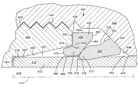
[0018] Figs. 1-4 illustrate different tube fittings 400, 400a, 400b, and 400c
in accordance with the
invention. The various fittings 400-400c include differing features and
combinations of features. A
tube fitting in accordance with the present invention can include one or more
of these features in
different combinations.
[0019] Showing one representative embodiment, Fig. 1 illustrates a tube
fitting 400 in accordance
with the invention, for use in coupling a tube 410 to a body 420. The fitting
400 includes a driver or
drive nut 440, an adaptor ring 450, and a ferrule 302. The body.420 and the
drive nut 440 may have
some "standard" features or dimensions, that is, features or aspects that are
corninonly found on
some fittings, as described below.
[0020] The tube 410 as illustrated has a cylindrical side wall 412 centered on
an axis 414. The side
wall 412 defines a fluid flow passage 416 in the tube 410. The tube side wall
412 has a cylindrical
outer surface 418 centered on the axis 414. (As used herein, the term "tube"
is intended to cover
hollow cylindrical pipes of different and varying diameters, including those
commonly known as
tube, pipe, and conduit.)
[0021] The body 420 has a cylindrical inner surface 422 centered on the axis.
The surface 422
defines a bore or tube soclcet 424 in which the end of the tube 410 is
received. The body 420 has an
external thread convolution 426 for engagement with the nut 440, as described
below. The fitting
400 is adapted to seal between the body 420 and the tube 410, and to secure
them to each other so
that the tube does not come out of the bore 424 in the body.
3
CA 02543573 2006-04-25
WO 2005/043023 PCT/US2004/036677
[0022] The body 420 has an annular end surface or back face 428 that extends
radially inward from
the thread convolution 426. The body 420 also has a frustoconical caroming
surface or tapered
surface 430 that extends between the inner surface 422 and the end surface
428. The caroming
surface 430 extends at an angle to the axis 414. In one exemplary embodiment,
as shown, the
caroming surface 430 extends at about a 12° angle to the axis 414. The
caroming surface 430 is
presented radially inward toward the axis 414 and axially in a direction
toward the drive nut 440.
The caroming surface 430 is located adjacent to the surface 422 and defines a
caroming mouth 432 of
the body 420 that is located adjacent to the tube socket 424. The body 420 has
an edge 434 at the
intersection of the caroming surface 430 and the end surface 428.
[0023] The driver or nut 440 includes a first cylindrical surface or inner
surface 442 centered on the
axis 414. The surface 442 defines a bore 444 through which the tube 410
extends. At a location
radially outward and spaced axially from the inner surface 442, the nut 440
has an internal thread
convolution 446 for engagement with the external thread 426 on the body 420.
[0024] The nut 440 has a frustoconical drive surface or drive face 448 that
extends radially and
axially between the inner surface 442 and the internal thread 446. The drive
face 448 extends at an
angle to the axis 414 and is presented radially toward the axis and axially
toward the body 420. In
the embodiment shown in Fig. 1. the drive face 448 extends at about a
45° angle to the axis 414. The
nut drive angle may be other than 45°.
[0025] The adaptor ring 450 and the ferrule 302 are located in the space
between the drive face 448
of the nut 440 and the body 420. The adaptor ring 450 can be, but need not be,
made from the same
material as the ferrule 302.
[0026] The adaptor ring 450 in the embodiment of Fig. 1 has a radially outer
portion 452 and a
radially inner portion 454 that are joined by a neck portion 456. The outer
portion 452 of the adaptor
ring 450 has a cylindrical outer surface 458 that extends parallel to the axis
414. The outer portion
452 of the ring 450 has an annular baclc face 460 that extends radially inward
from the back end of
the outer surface 458, in a direction normal to the outer surface and to the
axis 414. The baclc face
460 is presented axially in a direction toward the nut 440.
4
CA 02543573 2006-04-25
WO 2005/043023 PCT/US2004/036677
[0027] The outer portion 452 of the ring 450 also has an annular front face
462 that extends radially
inward from the front end of the outer surface 458, in a direction normal to
the outer surface and to
the axis 414. The front face 462 is presented axially in a direction toward
the end surface 428 of the
body 420. In the particular adaptor ring 450 that is shown in Fig. l, the
front face 462 has a greater
radial extent than the back face 460, for example, two times the radial extent
of the back face.
[0028] The adaptor ring 450 has a caroming surface 464 that is presented
radially inward toward the
axis 414 and also is presented axially toward the back of the fitting, in a
direction toward the drive
face 448 of the nut 440. The caroming surface 464 extends at an angle to the
axis 414, which, in the
embodiment illustrated in Fig. 1, is an angle of about 45°.
[0029] The inner portion 454 of the adaptor ring 450 has a cylindrical inner
surface 466 that extends
parallel to the axis 414. The inner surface 466 defines a bore 468 in which
the tube 410 is slidably
received. The iroler surface 466 overlies and is spaced apart from the outer
surface 418 of the tube
410, before the fitting 400 is made up. The adaptor ring 450 has an edge 470
at the intersection of
the inner surface 466 and the caroming surface 464.
[0030] The inner portion 454 of the ring 450 has an annular front face 472
that extends radially
outward from the inner surface 466, in a direction normal to the inner surface
and to the axis 414.
The front face 472 is presented axially in a direction toward the caroming
mouth 432 of the body
420. The front face 472 of the inner portion 454 of the ring is farther
forward in the fitting 400, that
is, is located closer to the body 420 and farther from the nut 440, than is
the front face 462 of the
outer portion 452 of the ring. A chamfer breaks the edge defined by surface
462 and surface 472.
[0031] The Timer portion of the adaptor ring 450 also has an engagement
surface 474 that extends
between and intercoroiects the front face 472 of the inner portion 454 of the
ring, and the front face
462 of the outer portion 452 of the ring. The engagement surface 474 may be a
single concave or
planar surface, or may be a series of concave or planar surfaces, or a
combination of various types of
surfaces. The engagement surface 474 spans the neclc portion 456 of the
adaptor ring 450, extending
between the front face 472 of the inner portion 454 and the front face 462 of
the outer portion 452.
The engagement surface 474 is presented toward the body 420 and, specifically,
toward the edge 434
on the body. On the opposite side of the adaptor ring 450, the caroming
surface 464 of the adaptor
ring 450 spans the neclc portion 456 of the adaptor ring, extending between
the inner surface 466 and
the back face 460 of the outer portion 452.
CA 02543573 2006-04-25
WO 2005/043023 PCT/US2004/036677
[0032] The dimensions of the adaptor ring 450 are selected so that its
radially inner portion 454 can
move into the caroming mouth 432 of the body 420, while the radially outer
portion 452 can not.
Specifically, movement of the adaptor ring 450 in a direction axially toward
the caroming mouth 430
of the body 420 is blocked, as described below, by engagement of the adaptor
ring engagement
surface 474 (or the front face 462) with the body 420.
[0033] When the fitting 400 is made up, the nut 440 is tightened on the body
420, and moves axially
toward the body (in a direction to the left as viewed in Fig. 1). The
45° drive face 448 of the nut
engages the back wall 324 of the ferrule 302. The ferrule 302 is driven
forward until it engages the
adaptor ring 450. The nose 310 of the ferrule 302 engages the 45° back
face 464 of the adaptor ring
450.
[0034] The adaptor ring 450 is moved forward by the ferrule 302 until it
engages the body 420. The
engagement surface 474 of the adaptor ring 450 engages the edge 434 on the
body 420 to act as a
stop for the adaptor ring. This engagement blocks any further substantial
movement of the adaptor
ring 450 toward the body 420, and may be sensed by sensing torque on the nut
400 to determine
sufficient pull up. The adaptor ring 450 is captured between the ferrule 302
and the body 420, and
the ferrule is captured between the adaptor ring and the nut 440.
[0035] The inner portion 454 of the adaptor ring 450 is located in the
caroming mouth 432 of the
body 420, radially inward of the caroming surface 430 but not in engagement
with the caroming
surface. Alternatively, the adaptor ring 450 can engage the caroming surface
430. The outer portion
452 of the adaptor ring 450 is located radially outward of the carroning
surface 430 of the body 420,
and axially between the end face 428 of the body and the drive face 448 of the
nut 440.
[0036] As the nut 440 is tightened further, the ferrule 302 is compressed and
plastically deformed,
and is driven into gripping and sealing engagement with the adaptor ring 450
and the tube 410. The
ferrule 302 may hinge and/or collet, and may be hardened to make it more
suitable for use with the
relatively steep 45° caroming angle of the adaptor ring 450.
[0037] The nose 310 of the ferrule engages the 45° caroming surface 464
on the adaptor ring, rather
than the 12° caroming surface 430 on the body 420. Thus, the nose 310
of the ferrule 302 is caromed
radially inward toward and into the tube 410 by a 45° caroming surface,
rather than by a 12°
caroming surface.
6
CA 02543573 2006-04-25
WO 2005/043023 PCT/US2004/036677
[0038] A seal is established between the engagement surface 474 of the adaptor
ring 450 and the
edge 434 of the body 420. This seal prevents fluid from the tube 410 from
passing radially outward
of the adaptor ring 450. This seal is not a sliding seal, that is, is not of
the type established when a
ferrule cams and slides against a caroming surface of a fitting body. In
contrast, the adaptor ring 450
is positively stopped from movement relative to the body 420, and the
engagement surface 474 thus
seals in a fixed manner against the edge 434 of the body. The adaptor ring 450
does not have to
establish a seal against the tube 410.
[0039] Another seal is established between the nose 310 of the ferrule 302 and
the caroming surface
464 of the adaptor ring 450. A third seal is established between the nose 310
of the ferrule 302 and
the tube 410. These seals together provide the desired sealing function of the
fitting 400, preventing
fluid from passing radially inward of the adaptor ring. At the same time, the
nose 310 of the ferrule
302 is driven into the material of the tube 310 to form a generally radial
shoulder 476, blocking
removal of the tube from the bore 424 in the body 420 and thus providing the
desired gripping
function of the fitting 400. The underside of the adaptor ring can be
configured to allow space for
the chip of tubing that is curled up by the ferrule nose. Thus, with the use
of the adaptor ring 450,
the fitting 400 can give up the increased grip benefit of the 12°
caroming surface, because excellent
grip is provided from the ferrule 302, that is caromed into the tube by the
45° caroming surface of the
adaptor ring.
[0040] Fig. 2 illustrates a tube fitting 400a that is similar to the tube
fitting 400 but which uses a
different adaptor ring. The fitting 400a, for use in coupling the tube 410 to
the body 420, includes
the same drive nut 440 and the same ferrule 302. The fitting 400a also
includes an adaptor ring 450a
which is slightly different from the adaptor ring 450 shown in Fig. 1.
Specifically, in the adaptor
ring 450a, the radially inner portion 454a is different than the radially
inner portion 454 in the
adaptor ring 450. Also, the engagement surface 474a in the adaptor ring 450a
is different than the
engagement surface 474 in the adaptor ring 400.
[0041] The radially inner portion 454a of the adaptor ring 450a has a convex
configuration including
a convex outer surface 478 presented toward the caroming surface 430 of the
body 420. The convex
outer surface 478 merges into a concave engagement surface 474a that merges
into the front face
462a of the radially outer portion 452a of the adaptor ring 450a. The
resulting configuration of the
adaptor ring 450a includes a "bullnose" shaped inner portion 454a that still
fits into the caroming
7
CA 02543573 2006-04-25
WO 2005/043023 PCT/US2004/036677
mouth 432 of the body 420, but that also projects radially outward
sufficiently to engage the
caroming surface 430 of the body when the fitting 400a is made up.
[0042] When the drive nut 440 pushes the ferrule 302 into the adaptor ring
450a, the adaptor ring is
pushed into engagement with the body 420, as shown in Fig. 2. The outer
surface 478 of the inner
portion 454a of the adaptor ring is wedged into tight engagement with the
caroming surface 430 of
the body 420. The radially extending front face 462a of the outer portion 452a
of the adaptor ring
450 preferably engages the end face 428 of the body to provide a stop. The
concave engagement
surface 474a of the adaptor ring 450a may or may not engage the edge 434 of
the body 420.
[0043] In the embodiment of Fig. 2, the adaptor ring 450a is interposed
between the ferrule 302 and
the body 420, so that the nose 310 of the ferrule engages the 45°
caroming surface 464a on the
adaptor ring, rather than the 12° carmning surface 430 on the body 420.
A seal is established
between the convex outer surface 478 on the radially inner portion 454a of the
adaptor ring 450a and
the caroming surface 430 of the body 420. Another seal is established between
the nose 310 of the
ferrule 302 and the caroming surface 464a of the adaptor ring 450a. A third
seal is established
between the nose 310 of the ferrule 302 and the tube 410. These seals together
provide the desired
sealing function of the fitting 400a. At the same time, the nose 310 of the
ferrule 302 is driven into
the material of the tube 310 to form a generally radial shoulder 476, blocking
removal of the tube
from the body 420 and thus providing the desired gripping function of the
fitting 400a.
[0044] Fig. 3 illustrates a tube fitting 400b that is similar to the fittings
400 and 400a, but including a
different adaptor ring. The fitting 400b, for use in coupling the tube 410 to
the body 420, includes
the same drive nut 440 and the same ferrule 302 (with a shortened back wall
324). The fitting 400b
also includes an adaptor ring 450b which is different from the adaptor ring
450 shown in Fig. 1 and
from the adaptor ring 450a shown in Fig. 2.
[0045] The adaptor ring 450b has an outer portion 452b that is longer axially
than the outer portion
of either of the rings 450 and 450a. The outer portion 452b of the adaptor
ring 450b includes a nose
portion 480 that projects forward (in a direction toward the body 420),
overlying the inner portion
454b of the ring and extending past the surface 474b. The outer portion 452b
also includes a tail
portion 482 that proj ects backward (in a direction toward the nut 440),
overlying a significantly
greater part of the ferrule 302 (in the illustrated embodiment, over most of
the ferrule) than does the
outer portion 452 of the adaptor ring 450 (Fig. 1).
8
CA 02543573 2006-04-25
WO 2005/043023 PCT/US2004/036677
[0046] When the fitting 400b is made up, as shown in Fig. 3, the nose portion
480 of the adaptor ring
engages the end face 428 of the body 420 to act as a stop for movement of the
adaptor ring. This
engagement limits further movement of the adaptor ring 450b in a direction
toward the body 420 and
provides a seal between the adaptor ring and the body. The nose 310 of the
ferrule 302 engages the
caroming surface 464b of the adaptor ring 450b to provide a seal, and is
carmned into the tube 410,
as described above, to grip and to provide an additional seal.
[0047] When the fitting 400b is made up, the tail portion 482 engages the
drive face 448 of the nut
440 to as a stop to limit movement of the nut 440 in a direction toward the
body 420. This can
provide torque sensing to ensure sufficient pull up of the fitting 400b.
[0048] Fig. 4 illustrates a tube fitting 400c that is similar to the fittings
400, 400a and 400b, and
including a different adaptor ring and ferrule. The fitting 400c, for use in
coupling the tube 410 to
the body 420, includes the same drive nut 440. The fitting 400c also includes
an adaptor ring 450c
which is different from the adaptor rings 450, 450a, and 450b. The fitting
400c also includes a
ferrule 302c which is different from the ferrule 302.
[0049] The back wall 324c of the ferrule 302c extends radially outward farther
than the back wall
324 of the ferrule 302 (Fig. 1). A stop surface 480 on the back wall 324c of
the ferrule 302c is
presented toward the body 420.
[0050] The outer portion 452c of the adaptor ring 450c includes a tail portion
482c that projects
backward (in a direction toward the nut 440), overlying a significantly
greater part of the ferrule 302
than does the outer portion 452 of the adaptor ring 450 (Fig. 1). The tail
portion 482c of the adaptor
ring 450c includes a stop surface 486 that is presented toward the nut 440 and
the back wall 324c of
the ferrule 302c.
[0051] The inner portion 454c of the adaptor ring 450c is elongated axially in
a forward direction,
compared to the inner portion 454 of the adaptor ring 450 (Fig. 1). The inner
portion 454c of the
adaptor ring 450c, like the bullnose on the adaptor ring 454a (Fig. 2), moves
into the caroming mouth
432 of the body 420 and engages the caroming surface 430 of the body. The
inner portion 454c of
the adaptor ring 450c seals against the tapered surface 430 of the body 420.
The concave
engagement surface 474c of the adaptor ring 450c, and the radially extending
front face 462c of the
9
CA 02543573 2006-04-25
WO 2005/043023 PCT/US2004/036677
outer portion 452c of the ring, may or may not engage the edge 434 of the body
420 and/or the end
face 428 of the body.
[0052] When the fitting 400c is made up, the stop surface 486 on the tail
portion 482c of the adaptor
ring 450c engages the stop surface 480 on the back wall 324c of the ferrule
302c. At the same time,
the front face 462c of the adaptor ring 450c engages the end surface 428 of
the body 420. As a
result, the outer portion 452c of the adaptor ring 450c and the back wall 324c
of the ferrule 302,
together, act as a stop to limit movement of the nut 440 in a direction toward
the body 420. This can
provide torque sensing to ensure sufficient pull up of the fitting 400c.
[0053] Fig. 5 illustrates a tube fitting 400d for use in coupling a tube 410
to a fitting body 420. The
fitting body 420 has a 12° caroming surface 430 that defines a caroming
mouth 432. The fitting 400d
includes a drive nut 440. The fitting 400d also includes an adaptor ring 450d
and a ferrule 302d.
[0054] The adaptor ring 450d has an extended nose 490 that fits into the
caroming mouth 432. The
nose 490 has a sharp edge 492 that digs into the ramming surface 430, upon
make-up, to provide a
seal between the adaptor ring 450d and the fitting body 420. The ferrule 302d
has a relatively small
nose 496 that fits under the relatively small 45° ramming mouth 494 of
the adaptor ring 450d. The
ferrule 302d seals against the 45° back end or ramming mouth 494 of the
adaptor ring 450d and grips
on the tube 410.
[0055] The fitting 400d does not have a positive stop built into it. Instead,
the fitting 400d is
designed to be pulled up a given number of turns of the nut, thereby ensuring
sufficient pull up of the
fitting.
[0056] Fig. 6 illustrates a tube fitting 400e for use in coupling a tube 410
to a fitting body 420. The
fitting 400e includes a drive nut 440. The fitting 400e also includes one of
three different adaptor
rings 500, 502, and 504 that are illustrated, and one of three different
ferrules 510, 512 and 514 that
are illustrated. As a result, there are nine possible combinations of the
illustrated parts.
[0057] The one adaptor ring 500 has a long and slender nose 520 that fits into
the ramming mouth
432. The nose 520 has a sharp edge 522 that digs into the ramming surface to
provide a seal
between the adaptor ring 500 and the fitting body 420. Because the nose 520 is
long and slender, it
produces less tendency to swell out the fitting body 420 when the fitting 400d
is made-up.
CA 02543573 2006-04-25
WO 2005/043023 PCT/US2004/036677
[0058] The adaptor ring 504, in contrast, has a shorter and thicker nose 524
that seals between the
adaptor ring and the fitting body 420. Because the nose 524 of the adaptor
ring 504 is shorter and
thicker in cross-section, it has a greater resistance to axial compression
under load. The qualities of
the intermediate adaptor ring 502 illustrated fall between the qualities of
the rings 500 and 504. The
three nose designs are illustrated to show that the length and thickness of
the nose are variables and
that the designer can select between them or can select a nose with a
different length and thickness.
[0059] The fitting 400e has a positive stop built into it. This can provide
torque sensing to ensure
sufficient pull up of the fitting. Specifically, the nut 440 is designed to
bottom out on the adaptor
ring 500-504. The three different ferrules 510-514 that are illustrated in
Fig. 6 have different lengths
and heights and thus allow for differing amounts of nut travel before the nut
440 bottoms out on the
back of the adaptor ring 500-504. The three ferrule designs 510-514 are
illustrated to show that the
size of the ferrule is a variable and that the designer can select between
them or can select a ferrule
with different dimensions. The choice of adaptor ring is dependent on which
one effectively makes a
seal against the caroming mouth without swelling the body while resisting
axial compression under
load. The choice of ferrule is based on to what extent it is desired to have
the ferrule grip into the
tube by the time the nut stops against the back side of the adaptor ring.
[0060] As noted above, the ferrule grips the tube to prevent the tube from
coming out of the tube
socket in the fitting body. Under high pressure, a significant amount of
strain can be present in the
tube, evidenced as an axially outwardly directed force on the tube and on any
component that is
attached to or gripping the tube. Sufficient strain on the tube, if
transmitted to the adaptor ring, can
break or reduce the seal between the adaptor ring and the body. It is
preferable to prevent this from
occurnng.
[0061] As illustrated schematically in Fig. 7, the nose 530 of the adaptor
ring 532, that is, the portion
that is located radially inward of the caroming surface 534, can have a
rounded tip 536. This helps to
avoid transmission of tube strain under high pressure to the adaptor ring.
[0062] In a second manner, the nose of the adaptor ring, that is, the portion
radially inward of the
caroming surface, can be ramped or chamfered radially outward, away from the
outer surface of the
tube, as illustrated schematically in Fig. 8. The adaptor ring 540 shown in
Fig. 8 is illustrated as
having an inner ramp surface or chamfer 542 that tapers radially outward as
measured in a direction
from the back of the ring toward the tip of the ring.
11
CA 02543573 2006-04-25
WO 2005/043023 PCT/US2004/036677
[0063] Third, the nose of the adaptor ring can be both rounded and ramped, as
illustrated
schematically by the adaptor ring 544 shown in Fig. 9.
[0064] In these manners, or in another manner, with an adaptor ring so
configured, then under high
pressure the tube can freely move and strain outward. As other examples, an
elliptical end portion
can be provided, or the nose portion can be broken off by broaching, for
example, to provide the
desired non-sharp configuration for the nose portion or end portion of the
adaptor ring.
Combinations of tapers and curved surfaces are also possible. The features of
the adaptor rings
shown in Figs. 7-9 and as described herein can equally apply to all the
adaptor rings illustrated.
During pull up, if the inside forward portion of the adaptor ring comes in
contact with the tube, it
touches with a negative rake angle with respect to the tube surface, that is,
an acute angle between
the tube surface and the surface of the inside forward portion of the adaptor
ring.
[0065] Figs. 10 and 11 show two further embodiments of the invention. Fig. 10
illustrates a tube
fitting 590 including a fitting body 592 having a tube socket 594 receiving an
end portion of a tube
596, a ferrule 598, and an adaptor ring 600. The adaptor ring 600 is
illustrated as having a taper and
rounded tip 602.
[0066] Fig. 11 illustrates a two ferrule tube fitting 560 including a fitting
body 562 having a tube
socket 564 receiving an end portion 566 of a tube 568. A driver 570 in the
form of a nut is coupled
to the fitting body 562 to drive a back ferrule 572, a front ferrule 574, and
an adaptor ring 576. The
adaptor ring 576 has a nose portion 578 that seals against a relatively
shallow, twelve degree to
twenty degree tapered surface 582 on the fitting body 562. The adaptor ring
576 has a back face 584
that forms a relatively less shallow carmning surface, in the range of from
about 30 degrees to about
45 degrees that is engaged by the nose portion of the front ferrule 574. The
back ferrule 572 is
captured between the front ferrule 574 and the nut 570. Upon make up (not
shown) of the fitting 560
both the front ferrule 574 and the baclc ferrule 572 grip and seal on the tube
568. In this
embodiment, as well as in the embodiment of Fig. 10, sufficient pull up of the
fitting can be ensured
by torque sensing or in another manner, such as by ensuring sufficient axial
stroke of the nut as
determined by number of turns of the nut.
[0067] Fig. 12 illustrates a self energizing effect under high pressure of an
adaptor ring in
accordance with the invention. The ring illustrated is the adaptor ring 450c
that is discussed above
with reference to Fig. 4. Under very high pressure, the tube 410 may begin to
pull out of the tube
12
CA 02543573 2006-04-25
WO 2005/043023 PCT/US2004/036677
socket in the fitting body 420. As this occurs, the ferrule 302c bites deeper
into the material of the
tube 410 to resist tube pullout and seal better. Fluid under pressure flows
into the annular cavity that
is located radially outward of the tube 410 and radially inward of the adaptor
ring 450c. The fluid
pressure acts to force the adaptor ring 450c away from the tube 410. The nose
portion 454c of the
adaptor ring 450c is pressed more tightly against the caroming surface 430 of
the fitting body 420.
The adaptor ring 450c is also pressed more tightly against the ferrule 302c.
As a result, the sealing
capability of the adaptor ring 450c is increased because of the increased
pressure in the tube 410.
[006] From the above description of the invention, those skilled in the art
will perceive
improvements, changes, and modifications in the invention. Such improvements,
changes, and
modifications within the skill of the art are intended to be included within
the scope of the appended
claims.
13