Language selection

Search

Patent 2544065 Summary

Third-party information liability

Some of the information on this Web page has been provided by external sources. The Government of Canada is not responsible for the accuracy, reliability or currency of the information supplied by external sources. Users wishing to rely upon this information should consult directly with the source of the information. Content provided by external sources is not subject to official languages, privacy and accessibility requirements.

Claims and Abstract availability

Any discrepancies in the text and image of the Claims and Abstract are due to differing posting times. Text of the Claims and Abstract are posted:

  • At the time the application is open to public inspection;
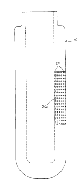
  • At the time of issue of the patent (grant).
(12) Patent: (11) CA 2544065
(54) English Title: FILTRATION ELEMENT HAVING A VARIABLE DENSITY SIDEWALL
(54) French Title: ELEMENT FILTRANT AVEC PAROI A DENSITE VARIABLE
Status: Granted
Bibliographic Data
(51) International Patent Classification (IPC):
  • B01D 29/27 (2006.01)
  • D04H 3/16 (2006.01)
(72) Inventors :
  • MORGAN, HOWARD WILLIAM (United States of America)
(73) Owners :
  • PALL CORPORATION (United States of America)
(71) Applicants :
  • MORGAN, HOWARD WILLIAM (United States of America)
(74) Agent: SMART & BIGGAR LP
(74) Associate agent:
(45) Issued: 2013-05-21
(22) Filed Date: 2006-04-19
(41) Open to Public Inspection: 2006-10-19
Examination requested: 2009-06-10
Availability of licence: N/A
(25) Language of filing: English

Patent Cooperation Treaty (PCT): No

(30) Application Priority Data:
Application No. Country/Territory Date
60/672,894 United States of America 2005-04-19
11/255,585 United States of America 2005-10-21

Abstracts

English Abstract

A filtration element formed of overlapping fibrous strands or components. Those fibrous strands at the side of the filtration element which first receives the gas flow being of one thickness and those fibrous strands at the side of the filtration element where the gas flow exits being of a thickness substantially less than the one thickness of the strands at the opposite sidewall of the element.


French Abstract

Un élément filtrant est formé de fils ou de composants fibreux se chevauchant. Ces fils fibreux sur le côté de l'élément filtrant qui reçoivent en premier le flux de gaz étant d'une épaisseur et les fils fibreux du côté de l'élément filtrant où le flux de gaz sort étant d'une épaisseur substantiellement inférieure à l'épaisseur des fils sur la paroi opposée de l'élément.

Claims

Note: Claims are shown in the official language in which they were submitted.

CLAIMS:

1. A fluid filter comprising an upstream side where fluid enters and a
downstream side
where fluid exits, said filter being formed of filaments and being in bag
form, said filaments
near said upstream side having a greatest thickness within said filter, said
filaments
continuously and gradually decreasing in thickness from said upstream side
toward said
downstream side such that pores between said filaments are largest near said
upstream side,
gradually decreasing in thickness toward said downstream side, thereby
allowing particles of
different sizes to be separated and evenly distributed throughout the filter,
at least some of
said filaments being cohesively bonded, said filaments having greatest
rigidity within said
filter near said upstream side, said filaments continuously and gradually
decreasing in rigidity
from said upstream side toward said downstream side to form a sidewall of said
filter having
sufficient stiffness so as not to require additional structural support to
maintain its shape, said
filaments varying progressively in transverse dimension.


2. A method for forming the fluid filter of claim 1 comprising:
- extruding a molten thermoplastic material while continually and gradually
reducing
a transverse dimension of the strands to form the filaments, and
- winding the filaments upon a mandrel to form the fluid filter.


3. The method according to claim 2, wherein the transverse dimension of
the strands is
continually and gradually reduced by continually and gradually increasing a
temperature of
5

the molten thermoplastic material during the step of extruding.

4. The method according to claim 3 or 4, wherein the transverse dimension of
the
strands is continually and gradually reduced by continually and gradually
increasing an air
pressure driving the step of extruding.


6

Description

Note: Descriptions are shown in the official language in which they were submitted.


CA 02544065 2011-10-17


FILTRATION ELEMENT HAVING A VARIABLE DENSITY SIDEWALL


SUMMARY OF THE INVENTION
[0002] This invention relates to a filtration element for gases and
will have application to bag
type filters.
[0003] In this invention, the filtration element was formed of
overlapping fibrous strands or
components with the strands varying in diameter or thickness, the largest of
which is at the side
of the filter which first receives the gas flow for filtration and the
smallest of which is at the
opposite side of the filter where the gas exists after passing through the
filtration element.
Further, the side of the filter which first receives the gas flow will
generally be more rigid than
the opposite side of the filter so as to provide a substantially
incompressible surface.
[0004] Accordingly, it is an object of this invention to provide a
filtration element which is
of economical construction and which is of efficient operation.
[0005] Still another object of this invention is to provide a
filtration element which is for
gases and which provides for more even distribution of filtered particulate
matter throughout the
thickness of the element.
[0006] Other objects of the invention become apparent upon the
reading of the following
description.
BRIEF DESCRIPTION OF THE DRAWINGS
[0007] Figure 1 is a fragmentary perspective view showing an example
of the apparatus
which can be used to make the filtration element of this invention.1

CA 02544065 2011-10-17


[0008] Figure 2 is a side view of a filter element in the form of a bag having
a portion of the
bag sidewall broken away to illustrate in cross-section the filtration strands
forming the sidewall
of the filter bag.
[0009] Figure 3 is a side view of the filter bag showing in illustrative form
the varying
thicknesses of the filtration strands.
DETAILED DESCRIPTION OF INVENTION
[0010] The preferred embodiment herein described is not intended to be
exhaustive or to
limit the invention to precise form disclosed. It is chosen and described to
explain the principles
Of the invention and its application and practical use to enable others
skilled in the art to best
utilize the invention.
[0011] This invention may be best understood by the following descriptions and
the
workings of the equipment which is used to produce the filter element, seen in
the drawing as a
filter bag 10. As illustrated in Figure 1, a quantity of material, preferably
polypropylene or other
thermoplastic materials capable of producing filaments when molten and air
dried, is introduced
into an extruder 12 at hopper 14 and is fed through a nozzle 16. A plurality
of ring heaters 18
circumscribe nozzle 16 and serve to produce heat sufficient to liquefy the
thermoplastic material
as it flows through the nozzle. Nozzle 16 terminates in a plurality of
laterally spaced discharge
outlets 22 through which the thermoplastic material in its molten state is
propelled in melted and
fibrous strands 20 by heated air from manifolds 23 toward a mandrel 28.
Mandrel 28 may be
formed from metal, wood or similar material and resembles in its outer
configuration the
intended shape of the filter bag 10 to be produced. Mandrel 28 is rotated
about an axis 35 within
the flow path of the fibrous strands 20 from nozzle discharge outlets 22.
Normally, Mandrel 28
is placed between 1 to 3 feet from outlets 22 and rotated at a constant speed
such as between 30
to 80 rpm. The fibrous material or strands 20 are sufficiently cooled as they
reach the mandrel
28 so as to be formed about the mandrel in layers.
[0012] In this invention, the diameters of the strands 20 are varied as the
thickness of the
sidewall 32 of bag 10 increases. This is best illustrated in viewing figures 2
and 3 where a
section of the sidewall of the filter bag has been broken away for
illustrative purposes. In figure
2

CA 02544065 2011-10-17


2 the strands 20 are shown in cross-section, the largest diameter strands
being at the inside of the
bag and the smallest diameter of the strands being at the outside of the bag
with the gas flow
through the bag being from the inside towards the outside of the bag. In
figure 3, there is shown
in illustrative form the varying thickness of the strands 20 with the strands
becoming
progressively thinner from the inside to the outside of the bag in the
direction of gas flow
through the bag. In this manner, the outer margin of the sidewall of the bag
will have its strands
more compactly layered so as to increase the degree of filtration as the outer
edges of the bag are
reached. Thus, the larger particulate matter being filtered from the gas will
first become
entrained within the filter bag closer to the inside of the bag with the
smaller particulate matter
becoming entrained closer to the outside of the bag. This will produce more
even distribution of
the filtered particulate matter throughout the bag.
[0013] The thickness of the strands 20 of bag 10 may range from 50 to 200
microns towards
the inside of the bag and progressively become smaller in transverse dimension
to .5 microns at
the outside surface of the bag with the bag being approximately % to 1 inch
thick. The precise
thickness or transverse dimension of the strands of the fibrous material and
thickness of the bag
can vary depending upon the type of material intended to be filtered and the
size of the filter bag.
[0014] In producing filter bag 10, the thicker strands are first wound upon
the mandrel and
then as the bag's thickness progressively increases, the temperature produced
by heaters 18 can
be increased so as to make the thermoplastic material more molten with the air
pressure
produced at manifolds 23 increased, thus increasing the length of the strands
and reducing their
transverse dimension. In this manner, by selectively increasing the
temperature of the molten
thermoplastic material and/or increasing the air pressure by which the molten
thermoplastic
material is driven through and propelled from the nozzles, the thickness of
the strands can be
selectively varied as they are wound upon the mandrel to produce the sidewall
of the filter bag or
cartridge depending upon the type of filtration element being produced.
[0015] Also, in addition to varying the thickness of the strands, by varying
the temperature of
the molten thermoplastic material and/or varying the volume of air by which
the material is
driven through and propelled from the nozzles, the stiffness of the strands
can be increased so
3

CA 02544065 2011-10-17


that the inner wall section 20a of the filter bag becomes stiff or rigid. Bag
side walls may
substantially collapse during use due to the gas pressure within the bag. This
reduces the bag's
permeability and filtering capacity. By rigidifying a wall section of the bag
at the side where the
gas first contacts, the bag strands remain open to provide intervals or voids
between the strands
to catch or entrain filtered particles. The depth of wall section 20a can
vary, even extending the
entire thickness of the filter bag, depending upon the filtration
characteristics desired.


4

Representative Drawing
A single figure which represents the drawing illustrating the invention.
Administrative Status

For a clearer understanding of the status of the application/patent presented on this page, the site Disclaimer , as well as the definitions for Patent , Administrative Status , Maintenance Fee  and Payment History  should be consulted.

Administrative Status

Title Date
Forecasted Issue Date 2013-05-21
(22) Filed 2006-04-19
(41) Open to Public Inspection 2006-10-19
Examination Requested 2009-06-10
(45) Issued 2013-05-21

Abandonment History

Abandonment Date Reason Reinstatement Date
2011-07-21 R30(2) - Failure to Respond 2011-10-17

Maintenance Fee

Last Payment of $624.00 was received on 2024-02-27


 Upcoming maintenance fee amounts

Description Date Amount
Next Payment if standard fee 2025-04-21 $624.00
Next Payment if small entity fee 2025-04-21 $253.00

Note : If the full payment has not been received on or before the date indicated, a further fee may be required which may be one of the following

  • the reinstatement fee;
  • the late payment fee; or
  • additional fee to reverse deemed expiry.

Patent fees are adjusted on the 1st of January every year. The amounts above are the current amounts if received by December 31 of the current year.
Please refer to the CIPO Patent Fees web page to see all current fee amounts.

Payment History

Fee Type Anniversary Year Due Date Amount Paid Paid Date
Application Fee $400.00 2006-04-19
Maintenance Fee - Application - New Act 2 2008-04-21 $100.00 2008-04-14
Maintenance Fee - Application - New Act 3 2009-04-20 $100.00 2009-03-20
Request for Examination $800.00 2009-06-10
Maintenance Fee - Application - New Act 4 2010-04-19 $100.00 2010-04-16
Advance an application for a patent out of its routine order $500.00 2011-03-16
Maintenance Fee - Application - New Act 5 2011-04-19 $200.00 2011-03-25
Reinstatement - failure to respond to examiners report $200.00 2011-10-17
Maintenance Fee - Application - New Act 6 2012-04-19 $200.00 2012-03-30
Final Fee $300.00 2013-03-05
Maintenance Fee - Application - New Act 7 2013-04-19 $200.00 2013-03-07
Maintenance Fee - Patent - New Act 8 2014-04-22 $200.00 2014-03-27
Registration of a document - section 124 $100.00 2014-04-09
Maintenance Fee - Patent - New Act 9 2015-04-20 $200.00 2015-04-09
Registration of a document - section 124 $100.00 2015-11-27
Maintenance Fee - Patent - New Act 10 2016-04-19 $250.00 2016-04-18
Maintenance Fee - Patent - New Act 11 2017-04-19 $250.00 2017-04-17
Maintenance Fee - Patent - New Act 12 2018-04-19 $250.00 2018-04-16
Maintenance Fee - Patent - New Act 13 2019-04-23 $250.00 2019-04-12
Maintenance Fee - Patent - New Act 14 2020-04-20 $250.00 2020-04-01
Maintenance Fee - Patent - New Act 15 2021-04-19 $459.00 2021-03-24
Maintenance Fee - Patent - New Act 16 2022-04-19 $458.08 2022-02-23
Maintenance Fee - Patent - New Act 17 2023-04-19 $473.65 2023-03-01
Maintenance Fee - Patent - New Act 18 2024-04-19 $624.00 2024-02-27
Owners on Record

Note: Records showing the ownership history in alphabetical order.

Current Owners on Record
PALL CORPORATION
Past Owners on Record
FILTER SPECIALISTS, INC.
MORGAN, HOWARD WILLIAM
PALL FILTER SPECIALISTS, INC.
Past Owners that do not appear in the "Owners on Record" listing will appear in other documentation within the application.
Documents

To view selected files, please enter reCAPTCHA code :


To view images, click a link in the Document Description column. To download the documents, select one or more checkboxes in the first column and then click the "Download Selected in PDF format (Zip Archive)" or the "Download Selected as Single PDF" button.

List of published and non-published patent-specific documents on the CPD .

If you have any difficulty accessing content, you can call the Client Service Centre at 1-866-997-1936 or send them an e-mail at CIPO Client Service Centre.


Document
Description 
Date
(yyyy-mm-dd) 
Number of pages   Size of Image (KB) 
Cover Page 2006-10-05 1 29
Abstract 2006-04-19 1 10
Description 2006-04-19 4 163
Claims 2006-04-19 2 43
Drawings 2006-04-19 3 65
Representative Drawing 2006-09-26 1 4
Claims 2009-07-03 5 186
Claims 2011-03-16 2 58
Claims 2011-10-17 1 26
Description 2011-10-17 4 161
Claims 2012-07-12 2 43
Cover Page 2013-05-02 1 30
Representative Drawing 2013-05-14 1 4
Correspondence 2011-04-12 1 13
Prosecution-Amendment 2011-04-21 3 91
Assignment 2006-04-19 2 76
Correspondence 2008-07-16 1 16
Correspondence 2008-07-04 3 138
Prosecution-Amendment 2009-06-10 1 29
Prosecution-Amendment 2009-07-03 6 208
Prosecution-Amendment 2011-03-16 3 108
Prosecution-Amendment 2011-03-23 1 15
Prosecution-Amendment 2011-04-01 3 88
Prosecution-Amendment 2011-10-17 1 17
Prosecution-Amendment 2011-10-17 8 334
Prosecution-Amendment 2012-01-18 2 54
Prosecution-Amendment 2012-07-12 5 227
Correspondence 2013-03-05 1 29
Assignment 2014-04-09 3 128
Change of Agent 2015-08-28 3 97
Office Letter 2015-09-21 1 23
Office Letter 2015-09-21 1 25