Note: Descriptions are shown in the official language in which they were submitted.
CA 02544261 2006-04-26
Description
MICROSTRIP ANTENNA AND CLOTHES ATTACHED WITH THE SAME
Technical Field
The present invention relates to a microstrip antenna
having flexibility to be attachable on clothes, and clothes
attached with the antenna.
Background Art
A microstrip antenna is used as an antenna for a mobile
station such as an automobile, or an antenna for a cellular
phone and an antenna for satellite communication.
A dielectric substrate or a feeding circuit substrate of
a conventional microstrip antenna was hard and heavy one. In
addition, a radiating conductor or a ground conductor was also
stiff, and the whole assembly was a hard and heavy one.
On the contrary, the present applicants have disclosed,
in Japanese application No. 2002-60010, a technology for
attaching a microstrip antenna to clothes or a hat and the like,
by composing a dielectric substrate, a radiating conductor or a
ground conductor by flexible material.
When a conventional microstrip antenna was fed by a pin
using a coaxial connector, an inner conductor of the coaxial
connector was enough to be directly soldered to a radiating
conductor of the microstrip antenna formed with metal foil such
as copper foil, while not to contact with a ground conductor of
the microstrip antenna formed with metal foil such as copper
foil, and also an outer conductor of the coaxial connector to
be directly soldered to the ground conductor.
CA 02544261 2006-04-26
However, to furnish flexibility to a microstrip antenna,
conductive cloth is used as a radiating conductor and a ground
conductor. In the case when a cloth woven by a polyester fiber
which coated with copper and covered with a surface nickel
layer on the copper coating and the like are used as a
conductive cloth, there was a problem such as insufficient
soldering on to the surface nickel layer, or being not suitable
to soldering because heat resistant temperature of polyester is
120°C.
Under these circumstances, it is an object of the
present invention to provide a microstrip antenna which can be
used onto cloth, due to being light weight, flexible and
without generating wrinkles, and be produced by soldering
handily during the production process, and clothes attached
with the same.
Disclosure of Invention
A microstrip antenna of the present invention and
clothes attached with the same have the following composition
to solve the above-described problems.
Namely, the microstrip antenna of the present invention
is equipped with a nearly flat plate-like radiating conductor,
a nearly flat plate-like ground conductor having larger area
than the radiating conductor, and a dielectric substrate set
between the radiating conductor and the ground conductor,
wherein one terminal of a feeding cable is connected to the
radiating conductor, and the other terminal is connected to the
ground conductor, the radiating conductor and the ground
conductor are characterized by being composed of nearly cloth-
2
CA 02544261 2006-04-26
like substances having flexibility and conductivity, and also
the dielectric substrate is composed of a nearly cloth-like
substance having flexibility and insulation property, and the
connection of the terminal of the feeding cable to the
radiating conductor or the ground conductor is composed of by
soldering through a conductive medium.
Hereat, the conductive medium may be composed of a
metallic plate-like substance adhered with conductive adhesives
at a surface opposing to the radiating conductor or the ground
conductor.
In particular, when the metallic plate-like substance is
made of copper as a main component, soldering can suitably be
functioned.
The conductive medium may be composed a metal coating
set on the heat resistant radiating conductor or the ground
conductor.
Also in this case, when the metal coating is made of
copper as a main component, soldering can suitably be
functioned.
The terminal of the feeding cable connected to the
radiating conductor may be composed a core wire which is an
inner conductor of the feeding connector, and also the terminal
of the feeding cable connected to the ground conductor may be
composed an outer conductor of the feeding connector, and the
core wire may pass through a pore part set in the ground
conductor, and may be connected to the radiating conductor
without contacted with the ground conductor.
The radiating conductor or the ground conductor may be a
cloth woven or compressed by symthtic reisn fiber such as a
3
CA 02544261 2006-04-26
polyester fiber or an aramid fiber, which fiber is coated with
copper and covered with a surface nickel layer on the copper
coating, and the dielectric substrate may be made of felt or
clothing fabric.
Clothes attached with a microstrip antenna may be formed
by attaching such a microstrip antenna at the exterior surface
of the clothes.
Brief Description of the Drawings
Fig. 1 is a cross-sectional front elevation view of a
microstrip antenna, and Fig. 2 is a plan view of a microstrip
antenna in usage pattern.
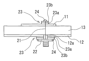
Reference numerals represent each as follows; 11:
radiating conductor, 12: ground conductor, 12a: pore part, 13:
dielectric substrate, 21: core wire, 22: outer conductor, 23:
conductive medium, 23a: conductive adhesives, 23b: metallic
plate-like substance, and 24: solder.
Best Mode for Carrying Out the Invention
Embodiments of the present invention are explained below
based on drawings.
Shape of a radiating conductor was expressed as thin
disk-like shape, and shapes of a ground conductor and a
dielectric substrate as thin square flat plate-like shape here,
as one example. However, these shapes are arbitrary and
various polygon or closed surfaces can be utilized, as
appropriate.
In addition, this Example is based on a pin feeding
system, however, a feeding system using a microstrip line or a
4
CA 02544261 2006-04-26
feeding system by electromagnetic coupling can be used, as
appropriate.
Such change in designing items is disclosed, for example,
in ~~Satellite Communication" (Naoshi Iida, Ohmsha Ltd., 1997)
and the like. The present invention can utilize, as
appropriate, items disclosed in such conventional references.
A cross-sectional front elevation view and a plan view
of a microstrip antenna are shown in Fig. 1 and Fig. 2,
respectively.
A microstrip antenna is equipped with a nearly flat
plate-like radiating conductor (11), a nearly flat plate-like
ground conductor (12) having larger area than the radiating
conductor (11), and a dielectric substrate (13) set between the
radiating conductor (11) and the ground conductor (12), and the
fundamental composition is that one terminal (21) of a feeding
cable is connected to the radiating conductor (11), and the
other terminal (22) is connected to the ground conductor (12).
In the present invention, as is described in detail
later, a microstrip antenna can be used onto clothes (30), due
to being light weight, and flexible and without generating
wrinkles, by using nearly cloth-like substances having
flexibility and conductivity as the radiating conductor (11)
and the ground conductor (12), and also by using a nearly
cloth-like substance having flexibility and insulation property
as the dielectric substrate (13).
In Fig. 2, the lower surface of a ground conductor (12)
is adhered to the exterior surface (31) of clothes (30).
Copper being relatively cheap and having low electric
resistance is usually used as a radiating conductor (11) and a
CA 02544261 2006-04-26
ground conductor (12), however, in the present invention, a
conductive cloth-like substance is used.
As a conductive cloth, it is made possible to use a
cloth woven or compressed by symthtic reisn fiber such as a
polyester fiber or an aramid fiber and the like, which fiber is
coated with copper and covered with a surface nickel layer on
the copper coating can be utilized.
In addition, a cloth-like substance formed by a
conductive fiber can also be utilized.
A conductive fiber includes, for example, such one as
obtained by melt-conjugate-spinning of two components of a
conductive layer compounded, in high concentration, with
conductive fine particles such as carbon black or a metallic
compound, and a usual polymer layer to protect the conductive
layer and the like.
As a dielectric substrate (13), a cloth-like substance
having flexibility and insulating property, such as clothing
fabric including felt or cloth or blanket and the like is used.
Larger relative dielectric constant of a dielectric
substrate (13) shortens radiowave wavelength inside the
dielectric, and contributes to compact sizing of an antenna.
On the other hand, low relative dielectric constant and
a thicker dielectric substrate (13) are preferable to broaden
bandwidth of a microstrip antenna.
Here, in the present invention, the connection of the
terminals (21) (22) of the feeding cable to the radiating
conductor (11) or the ground conductor (12) is carried out by
solder (24) through the conductive medium (23).
In an Example illustrated, the terminal of the feeding
6
CA 02544261 2006-04-26
cable connected to the radiating conductor (11) is a core wire
(21) which is the inner conductor of the feeding connector, and
the terminal of the feeding cable connected to the ground
conductor (12) is the outer conductor (22) of the feeding
connector. The core wire (21) passes through a pore part (12a)
set in the ground conductor (12), which part is provided there
so as to have a little larger diameter than the core wire (21),
and connected to the radiating conductor (11) without contacted
with the ground conductor (12).
In this connection, the core wire (21) may be contacted
with or separated from the dielectric substrate (13). To be
separated, a hole may be set to the dielectric substrate (13)
similarly as the pore part (12a) , and a cylinder and the like
may be set, as appropriate.
In the case when a conductive cloth woven or compressed
by a polyester fiber which is coated with copper and covered
with a surface nickel layer on the copper coating is used as
the radiating conductor (11) or the ground conductor (12), to
furnish flexibility to a microstrip antenna, soldering was
conventionally difficult.
Therefore, in the present invention, the solder (24) is
made through the conductive medium (23) composed of the
metallic plate-like substance (23) adhered with conductive
adhesives (23a) at a surface opposing to the radiating
conductor (11) or the ground conductor (12). As material for
the metallic plate-like substance (23b), copper is preferable
and as an embodiment thereof, a sheet-like substance such as a
thin film or a tape can be utilized, as appropriate, as well as
a thin plate having certain thickness and strength.
7
CA 02544261 2006-04-26
By using the conductive medium (23), soldering can be
carried out easily and in a short time. In addition, thermal
degradation of conductive cloth such as a polyester can be
suppressed, because it does not directly contacted with a high
temperature solder iron or the solder (24).
The conductive medium (23) may be a conductive tape
integrated combination of the conductive adhesives (23a) such
as an acrylic-based conductive adhesive and the metallic plate-
like substance (23b) such as copper foil and the like.
The conductive medium (23) may be composed of a metallic
coating of copper and the like set on the radiating conductor
(11) or the ground conductor (12).
Thus, cloth made of a heat resistant aramid fiber and
the like, treated with a copper coating can be utilized as the
radiating conductor (11) or the ground conductor (12) attached
with the conductive medium (23).
Example
An antenna having structure shown in Fig. 1 was produced
for experiment to confirm operability of a microstrip antenna
of the present invention.
As the radiating conductor (11), conductive cloth having
circular shape with a diameter of 60 mm, a thickness of 0.15 mm,
a surface density of 80 g/m2, and a reflection loss and a
transmission loss at 2.5 GHz of 0.03dB and 74 dB, respectively,
was used.
As the ground conductor (12), conductive cloth having
square shape with a side length of 150 mm, a thickness of 0.15
mm, a surface density of 80 g/mz, and a reflection loss and a
8
CA 02544261 2006-04-26
transmission loss at 2.5 GHz of 0.03 dB and 74 dB, respectively,
was used.
As the dielectric substrate (13), cheap square felt
having a side length of 150 mm, a thickness of 1 mm, and a
relative dielectric constant of 1.43 was used.
As a feeding connector, a nearly square shape SMA
connector having a side length of grounding surface contacting
with the ground conductor (12) of 12.5 mm, was used.
As the conductive medium (23) , a copper foil tape (No.
1181 produced from Sumitomo 3M Ltd.) was used.
The following results were obtained: Return loss of this
antenna was about -20 dB under non-bent state, and resonance
frequency was 2.505 GHz, which was gradually decreased with
bending.
Gain was 6.5 dB, which showed 4.1 dB even under bending
in U character, which is a practically acceptable value.
Beam width was found to be widened with further bending
of an antenna, from the radiation pattern. Lowering of the
gain under bending is caused also by the broadening effect of
the beam width, in addition to change in resonance frequency.
Industrial Applicability
A microstrip antenna of the present invention, and
clothes attached with the antenna have the following effects by
having the composition as described above.
Namely, the microstrip antenna can be incorporated in
cloth-like shape, which is light weight, flexible and does not
generate wrinkles, using cheap material, and can easily be used
by being stitched or embedded into clothes or a hat, and be
9
CA 02544261 2006-04-26
produced by soldering handily during the production process.
Therefore, clothes attached with this microstrip antenna can be
provided, which can be utilized for a spacesuit or location
detective device in combination with a chipped GPS receiver and
a location information transmitter and the like.